
Stock s4 turbo timing maps: a warning to those on the stock ECU


Stock s4 turbo timing maps: a warning to those on the stock ECU
First I'd like to thank the Rtek guys for disassembling the factory calibrations and Rotaryrocket88 for preparing these tables and charts.
This thread consists of
1) information about the stock s4 T2 timing maps, for curiosity's sake
2) a warning for those of you with modified turbo engines on the stock ECU, especially high compression builds.
How Timing Calculations Work
The FC calculates ignition timing mostly based on the airflow meter signal and the engine speed.
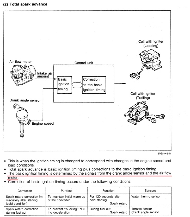
There is nothing unusual about this. Piston engines that directly measure airflow work the same basic way (Evo, STi, Corvette engines). The FC timing maps are based on a calculated engine load. We don't know the exact formula in this case, but on these types of systems usually engine load is proportional to airflow divided by rpm. The more air being crammed into the intake stroke, the more load.
Generally speaking, we want the spark plug to fire earlier (advance, a higher number) as engine speed increases to give the mixture enough time to burn. We want to fire the plug later (a lower number) the more engine load increases, in order to prevent an undesireable explosion (knock).
Timing Maps
Here is the stock leading timing map on an s4 T2:
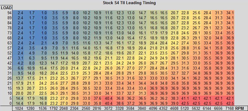
Y axis is engine load, X axis is rpm, Z axis is degrees BTDC. The general trend is this: looking horizontally at a given engine load, timing will advance (higher number) as rpm increases. Looking vertically, at a given rpm timing will decrease (lower number) as more airflow is crammed into the engine. Here is one important thing to notice: the top 3 rows are basically the same. When load gets over about 80, the ECU will not pull additional timing to account for more airflow.


For the sake of brevity I can't go too in-depth here about trailing timing but basically as load increases, the trailing plugs will fire later relative to the leading plugs. Thus "split" will increase up to a point. You can see here that from the factory it maxes at about 15-16 degrees split which is considered conservative.
This thread consists of
1) information about the stock s4 T2 timing maps, for curiosity's sake
2) a warning for those of you with modified turbo engines on the stock ECU, especially high compression builds.
How Timing Calculations Work
The FC calculates ignition timing mostly based on the airflow meter signal and the engine speed.
There is nothing unusual about this. Piston engines that directly measure airflow work the same basic way (Evo, STi, Corvette engines). The FC timing maps are based on a calculated engine load. We don't know the exact formula in this case, but on these types of systems usually engine load is proportional to airflow divided by rpm. The more air being crammed into the intake stroke, the more load.
Generally speaking, we want the spark plug to fire earlier (advance, a higher number) as engine speed increases to give the mixture enough time to burn. We want to fire the plug later (a lower number) the more engine load increases, in order to prevent an undesireable explosion (knock).
Timing Maps
Here is the stock leading timing map on an s4 T2:
Y axis is engine load, X axis is rpm, Z axis is degrees BTDC. The general trend is this: looking horizontally at a given engine load, timing will advance (higher number) as rpm increases. Looking vertically, at a given rpm timing will decrease (lower number) as more airflow is crammed into the engine. Here is one important thing to notice: the top 3 rows are basically the same. When load gets over about 80, the ECU will not pull additional timing to account for more airflow.
For the sake of brevity I can't go too in-depth here about trailing timing but basically as load increases, the trailing plugs will fire later relative to the leading plugs. Thus "split" will increase up to a point. You can see here that from the factory it maxes at about 15-16 degrees split which is considered conservative.
Stock timing maps on a modified car
Rotaryrocket88 has taken some logs on his turbo vert with basic modifications and a little more boost than wastegate pressure. This Excel chart shows boost and load. Once load gets over about 80, the ECU will not pull additional timing.
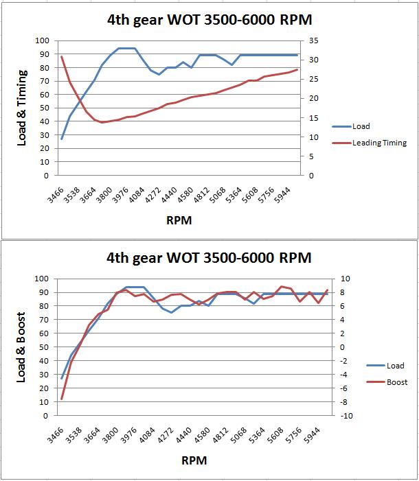
The good news is that these timing maps were meant to run on 87 octane. So there is a decent safety margin for a stock turbo and stock ports running on premium fuel. Once you go with a bigger turbo and a ported engine the risks of detonation on stock timing maps will increase, especially over 4000 rpm. You have to throw a lot of fuel at the engine and hope you can keep intake temps down. Using an SAFC or other piggyback could potentially increase the risk of detonation when you are "leaning out" bigger injectors. If the altered AFM signal ends up tricking the ECU into putting you into a lower load cell that could result in more advanced ignition timing.
The risk increases on 6 port turbo setups with 9.4:1 or 9.7:1 rotors. You really need some kind of engine management system with timing control. The Rtek 2.1 will allow you to modify these load-based timing maps, or switch to a map that calculates timing based on the MAP sensor signal. This allows you to bypass the measuring limitations of the AFM. A full standalone will also give you the timing control you need.
If anyone has an Rtek 2.1 with s4 non turbo, s5 non turbo, or s5 turbo I would appreciate it if you could put together some charts like RotaryRocket88 has done. It would be interesting to compare all the stock timing maps.
Rotaryrocket88 has taken some logs on his turbo vert with basic modifications and a little more boost than wastegate pressure. This Excel chart shows boost and load. Once load gets over about 80, the ECU will not pull additional timing.
The good news is that these timing maps were meant to run on 87 octane. So there is a decent safety margin for a stock turbo and stock ports running on premium fuel. Once you go with a bigger turbo and a ported engine the risks of detonation on stock timing maps will increase, especially over 4000 rpm. You have to throw a lot of fuel at the engine and hope you can keep intake temps down. Using an SAFC or other piggyback could potentially increase the risk of detonation when you are "leaning out" bigger injectors. If the altered AFM signal ends up tricking the ECU into putting you into a lower load cell that could result in more advanced ignition timing.
The risk increases on 6 port turbo setups with 9.4:1 or 9.7:1 rotors. You really need some kind of engine management system with timing control. The Rtek 2.1 will allow you to modify these load-based timing maps, or switch to a map that calculates timing based on the MAP sensor signal. This allows you to bypass the measuring limitations of the AFM. A full standalone will also give you the timing control you need.
If anyone has an Rtek 2.1 with s4 non turbo, s5 non turbo, or s5 turbo I would appreciate it if you could put together some charts like RotaryRocket88 has done. It would be interesting to compare all the stock timing maps.
Does this load calculation factor in timing changes based on the presure/boost sensor ? or is that a separate modifier. Obiously stock ecu wont retard timing past the fuel cut lvl but it should up to it
The MAP sensor supplies a signal to the gauge in the dash on turbo models. On the s5 it is involved in the factory boost control system. We don't know all the details for its use on turbo models, but it has a small role in some fuel injection calculations. It's also used as part of the BAC valve, EGR, and secondary air injection (ACV/airpump) systems. See pages 4-54 through 4-57 of the training manual.
I think Pocketlogger's reference to the ECU not pulling additional timing beyond ~9 psi is in regard to how the load timing maps were designed. On the graph arghx posted, you can see that I was hitting the maximum timing retard (80+ load) pretty much the whole time I was making about 8 psi. The top 3 cells of the timing maps are all the same number, so if someone cranks the boost up even further, there won't be any more timing pulled. Load will probably increase to 90-100%, but the new cells still have the same values as before.
Trending Topics
Wow, there's a lot of 0 split areas, and even some negative split areas? I didn't think Mazda went that way.
Also, love that 31 degrees advance at 6656 rpms and full load. I'm only running 19 degrees between 8 psi and 6500rpms.
Also, love that 31 degrees advance at 6656 rpms and full load. I'm only running 19 degrees between 8 psi and 6500rpms.

Thread
Thread Starter
Forum
Replies
Last Post
trickster
2nd Generation Specific (1986-1992)
25
Jul 1, 2023 04:40 PM
befarrer
Microtech
3
Aug 22, 2015 05:52 PM