She Followed Me Home, Honest
 04-17-15, 08:37 AM
#1826
Well, we got a spring snow (actually more like slush with pretensions of grandeur) yesterday but desperation drove me to the junkyard anyway. It was horrendous and uncomfortable and I regretted the decision almost immediately but my precarious intake demanded immediate attention.
Jesseluck's suggestion did get me thinking in a new direction and that was one thing I was looking for, the other was an airbox.
I found a cardboard box that I trimmed to (crudely) fit the corner of the bay...any airbox that would fit inside was a potential winner.
Junkyarding in the snow is not very productive because you can't see anything.
Most cars have open hoods and I normally cruise down the row making snap decisions pretty quickly. Yesterday though I had to wipe 5" of wet slush off every bay I wanted to examine...my hands were frozen.
Yet I persevered- a real sign in my confidence in the glue joint- and finally, in the Ford section I got lucky.
"Lucky" being a relative term.
Here's the thing; the apparent available space for the airbox is quite deceptive. It's oddly shaped and although I have no doubt the factory could cast a shape that maximized the available area, I had to work with what I could find.
The critical parameters were placement of the outlet port (connection to the AFM), size and shape, potential mounting points and lastly, location of the intake.
And I found such a creature.
Maybe.
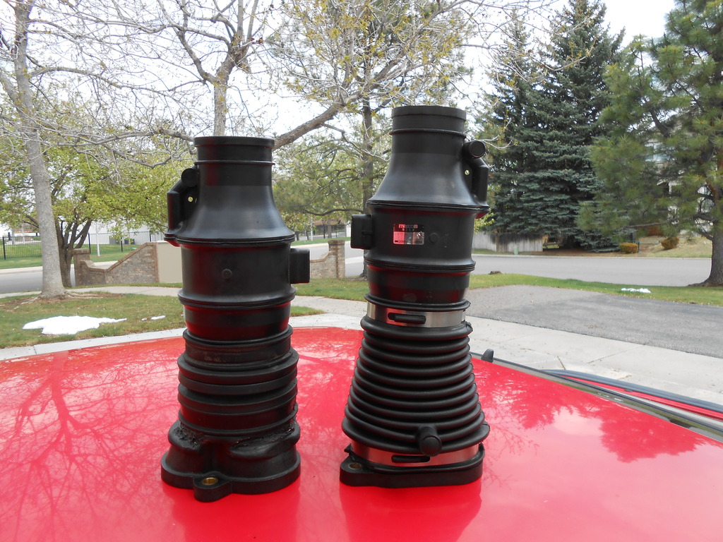
The main concern is size/volume compared to the Mazda original...the Ford replacement is only about 2/3 the size, the filter maybe 50% as large.
I have no idea if this will be a problem, my grasp of fluid dynamics being rudimentary at best.
It's worth a try though and that's today's project.
The main advantage of the airbox over a cone filter is that the airbox solidly supports the outer end of the intake, which takes most of the stress off the glue joint (I still have a plan for that modified elbow but need more yard time to explore it).
And (at least in my idealized perfect world) it will look kinda OEM.
Kinda.
I gave the part a quick bath last night (no sense getting dirty handling it but it will need more cosmetic attention later) and we'll see what's what in a bit.
Pics to follow.
Jesseluck's suggestion did get me thinking in a new direction and that was one thing I was looking for, the other was an airbox.
I found a cardboard box that I trimmed to (crudely) fit the corner of the bay...any airbox that would fit inside was a potential winner.
Junkyarding in the snow is not very productive because you can't see anything.
Most cars have open hoods and I normally cruise down the row making snap decisions pretty quickly. Yesterday though I had to wipe 5" of wet slush off every bay I wanted to examine...my hands were frozen.
Yet I persevered- a real sign in my confidence in the glue joint- and finally, in the Ford section I got lucky.
"Lucky" being a relative term.
Here's the thing; the apparent available space for the airbox is quite deceptive. It's oddly shaped and although I have no doubt the factory could cast a shape that maximized the available area, I had to work with what I could find.
The critical parameters were placement of the outlet port (connection to the AFM), size and shape, potential mounting points and lastly, location of the intake.
And I found such a creature.
Maybe.
The main concern is size/volume compared to the Mazda original...the Ford replacement is only about 2/3 the size, the filter maybe 50% as large.
I have no idea if this will be a problem, my grasp of fluid dynamics being rudimentary at best.
It's worth a try though and that's today's project.
The main advantage of the airbox over a cone filter is that the airbox solidly supports the outer end of the intake, which takes most of the stress off the glue joint (I still have a plan for that modified elbow but need more yard time to explore it).
And (at least in my idealized perfect world) it will look kinda OEM.
Kinda.
I gave the part a quick bath last night (no sense getting dirty handling it but it will need more cosmetic attention later) and we'll see what's what in a bit.
Pics to follow.

 04-17-15, 09:14 AM
#1828
We were 70� Tuesday, 60� on Wednesday and 35� yesterday.
It's sloppy and wet, if you tried to make a snowball most would squeeze out as water and leave a little icy pit.
Probably all be gone by Saturday afternoon.
So basically, perfect garage weather.
It's sloppy and wet, if you tried to make a snowball most would squeeze out as water and leave a little icy pit.
Probably all be gone by Saturday afternoon.
So basically, perfect garage weather.
04-17-15, 10:18 AM
#1829
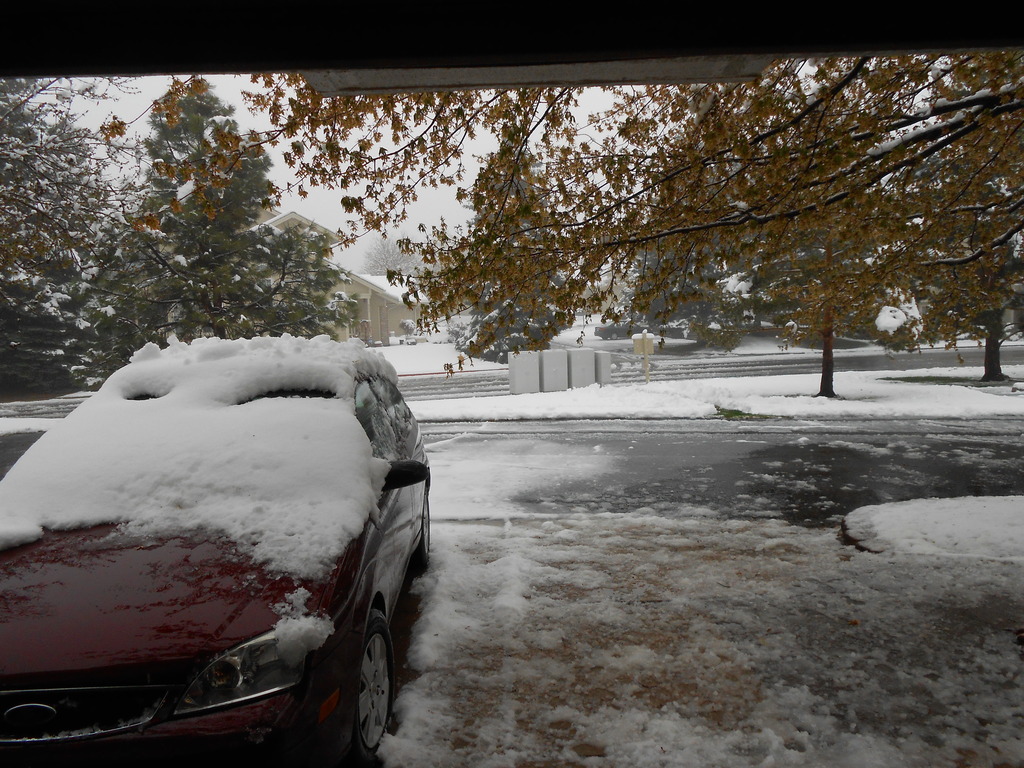
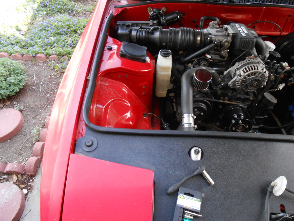
View out the garage:
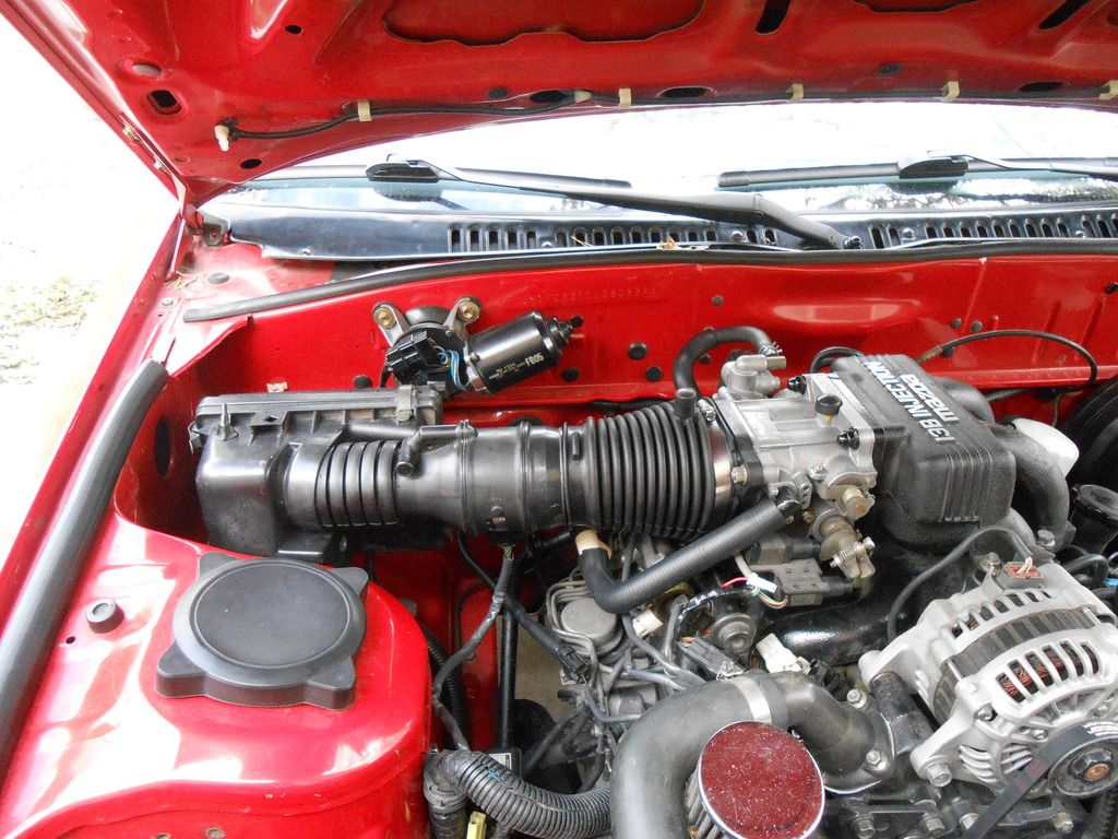
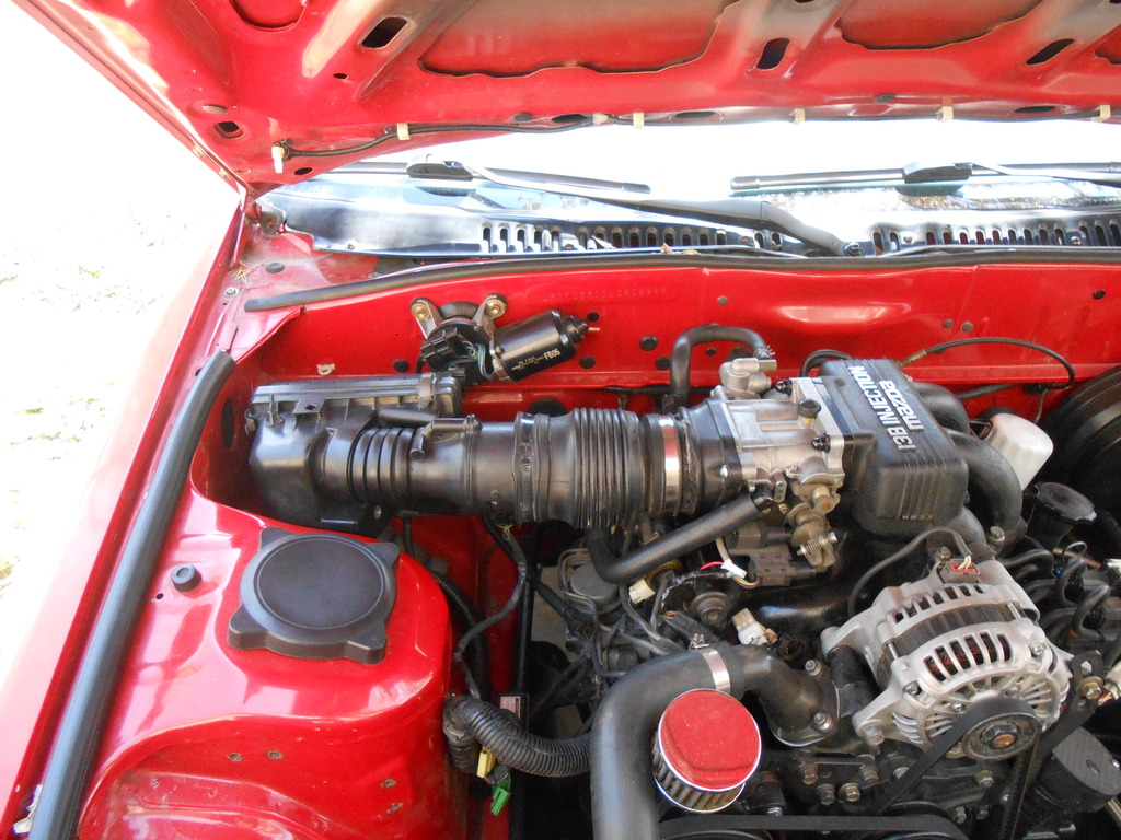
Well, preparation paid off, at least to the extent that the airbox fits the space and is easily connected to the AFM.
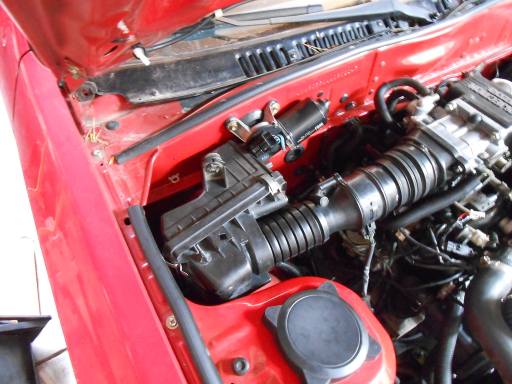
This is actually 90� off the way I envisioned in the yard, but it's only the first attempt and I need to play around with it more.
This orientation is interesting to me because it fits almost exactly one of the intake sources I'd idly toyed with all these years...the wiper linkage cavity.
Look carefully and you'll see the intake on the box is right behind the wiper motor.
Remove the motor, install a simple 90� bend into the newly vacated hole and viola!, we're pulling air from the base of the windshield, isolated from the engine bay entirely.
Have no idea if it'd work but it's always seemed like a reasonable possibility.
That would entail figuring out a new wiper setup though, and right now that's a bridge too far.
I've already (temporarily) lost washer function, can't keep casually deleting necessary systems pursuing what is essentially a whim.
Also visible, pointing straight up on top, is a mounting bracket.
There's another one on the bottom and these two protuberances prevent the box from sitting as originally intended. I'd need to cut them off to keep playing with position but all too often I've cut off brackets etc. that would have been useful later, so I'm hesitant to make a snap decision.
Gotta put my thinking cap on.
Well, preparation paid off, at least to the extent that the airbox fits the space and is easily connected to the AFM.
This is actually 90� off the way I envisioned in the yard, but it's only the first attempt and I need to play around with it more.
This orientation is interesting to me because it fits almost exactly one of the intake sources I'd idly toyed with all these years...the wiper linkage cavity.
Look carefully and you'll see the intake on the box is right behind the wiper motor.
Remove the motor, install a simple 90� bend into the newly vacated hole and viola!, we're pulling air from the base of the windshield, isolated from the engine bay entirely.
Have no idea if it'd work but it's always seemed like a reasonable possibility.
That would entail figuring out a new wiper setup though, and right now that's a bridge too far.
I've already (temporarily) lost washer function, can't keep casually deleting necessary systems pursuing what is essentially a whim.
Also visible, pointing straight up on top, is a mounting bracket.
There's another one on the bottom and these two protuberances prevent the box from sitting as originally intended. I'd need to cut them off to keep playing with position but all too often I've cut off brackets etc. that would have been useful later, so I'm hesitant to make a snap decision.
Gotta put my thinking cap on.
 04-17-15, 04:58 PM
#1831
Yeah, all options are still open.
The first (mostly) acceptable iteration is done.
With one minor hardware exception (should replace a bolt with a stud) the assembly is well mounted, solid without being rigid and easily removed/installed.
As the earlier pics demonstrate, it was possible to get the entire box into the area available but it looked all cattywhompus and was obviously a random part crammed into a random space.
I ended up cutting off the bottom half of the box, preserving only the collar necessary to hold the clips and the filter. This freed up the remaining assembly to fit in a semi-rational manner.
Now that there's a tangible part in situ to look at, I find the process so much easier.
Not sure where to go for version 2 (?) but I'll see how the current setup works before thinking on it much more. I really need to go back to the other end, the adaptor I made, and figure out how to foolproof that. I have an idea but need to junkyard the part.
And the yard will be a swamp tomorrow, what with all this pretend snow.
The sky has cleared, temp has risen and 50% of it has melted off already...gonna be messy in the yard for a while.
Still might try to go in the morning though...
04-19-15, 06:15 PM
#1832
Close...maybe there.
As expected, half of the junkyard was an ankle deep lake (and me without my waders!) and the other half was a treacherous morass but I soldiered through the first world inconvenience and after a hour and a half, scored a reasonable facsimile of what I envisioned.
Version #1 works perfectly but the glue joint is a nagging worry, one I'd like eliminated.
So, can the need for the joint be eliminated?
All it did was attach a round end- easy to slip a tube over but maybe a correctly sized rubber boot could be persuaded to conform to the gently triangle shape of the flange base.
Start with these three parts:
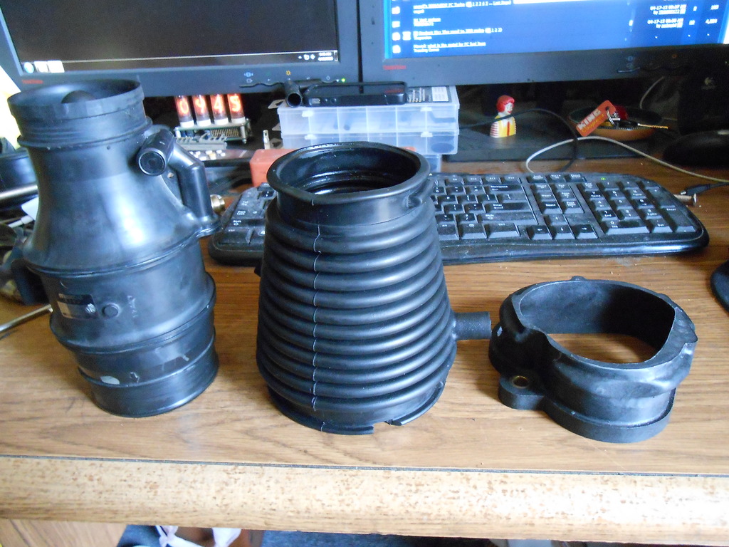
And make this (new one on right):
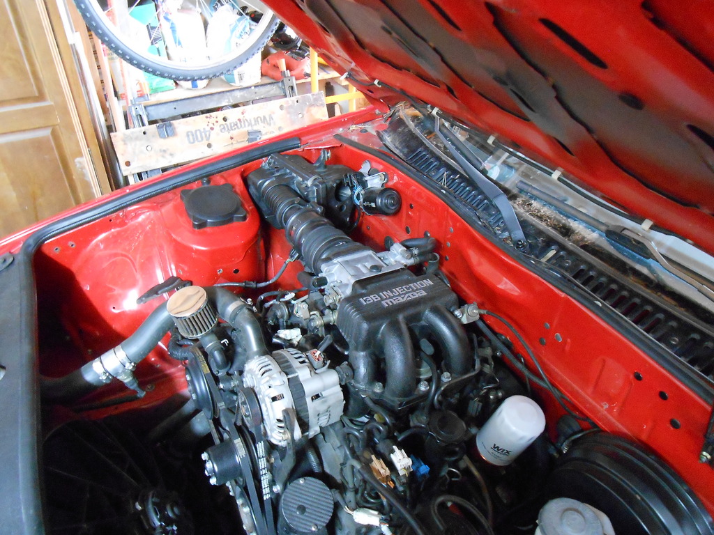
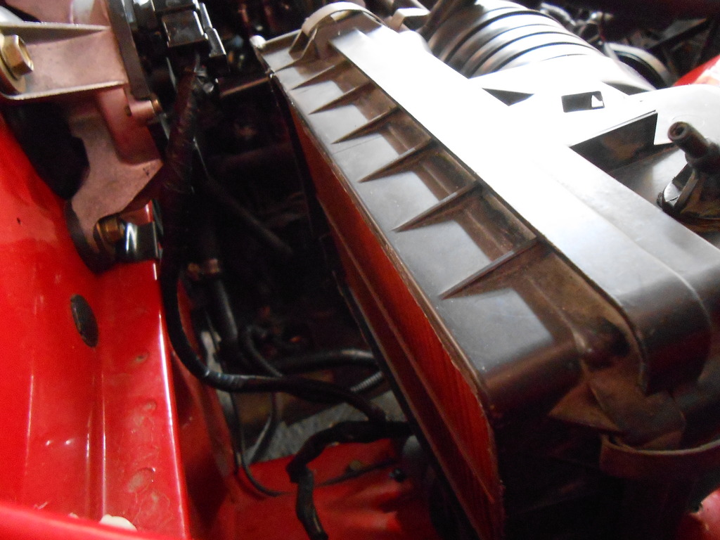
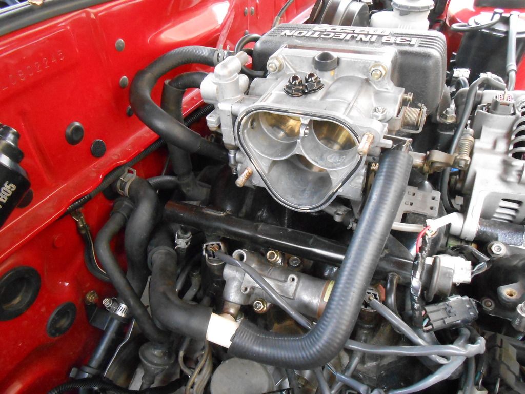
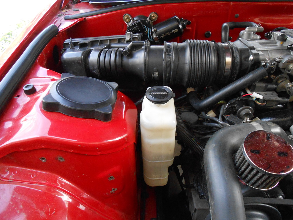
Before putting it on I thought to show the new metered air arrangement, long as it was exposed:
And it ends up like so:
It's as reasonably close to perfect as $20 and a junkyard will get you.
But I'm afraid the pictures are a lie.
V.1 was dead simple to install, under a minute maybe.
This one is a bit cantankerous.
And by that I mean ridiculously hard.
A shown in the comparison/roof shot above, the boot/clamp fit and seal perfectly.
What they don't do is leave any clearance for the hardware. It's possible to get the studs through the holes but there is zero space for the nuts.
It's a beautiful part that can't be mounted.
Well I'll be danged (or words to that effect).
After some thought, the easiest, least destructive/permanent course was to remove the boot from the flange, bolt the flange onto the throttle body and then try to weasel the boot and clamp on in situ.
This is what yo see above.
What you don't see is the massive leak at the bottom.
I'm pretty sure I'm going to have to remove the dynamic chamber from the exten mani and work with the intake off the car. The boot requires a lot of finessing to get it on right and there's no room or good sightline in position.
And if you're wondering why I don't pull just the throttle body, well, the boot is such a large diameter that access to the two lower nuts is gone.
The hits just keep coming.
Reasonably confident it can be properly assembled in this manner and I'm pleased enough with the look that I'm willing to invest the extra 10-20 minutes in the attempt.
But...and this is kind of a biggie...even if it does work out, adding time to the "normal" maintenance of the car violates a cardinal precept of the Because Streetcar! ethos and I'm not sure how I feel about that.
Assuming assembly success tomorrow, I can continue to explore better adaptor options with the complete spare setup I now have and with luck, come up with a part that better fulfills all the desired features.
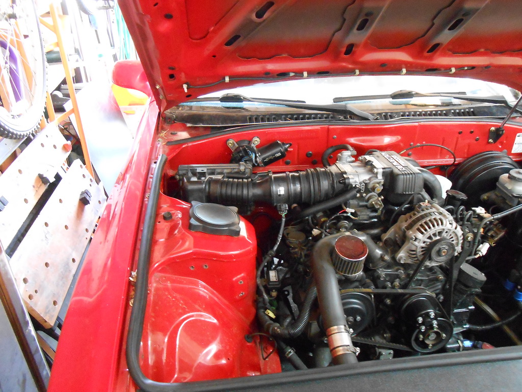
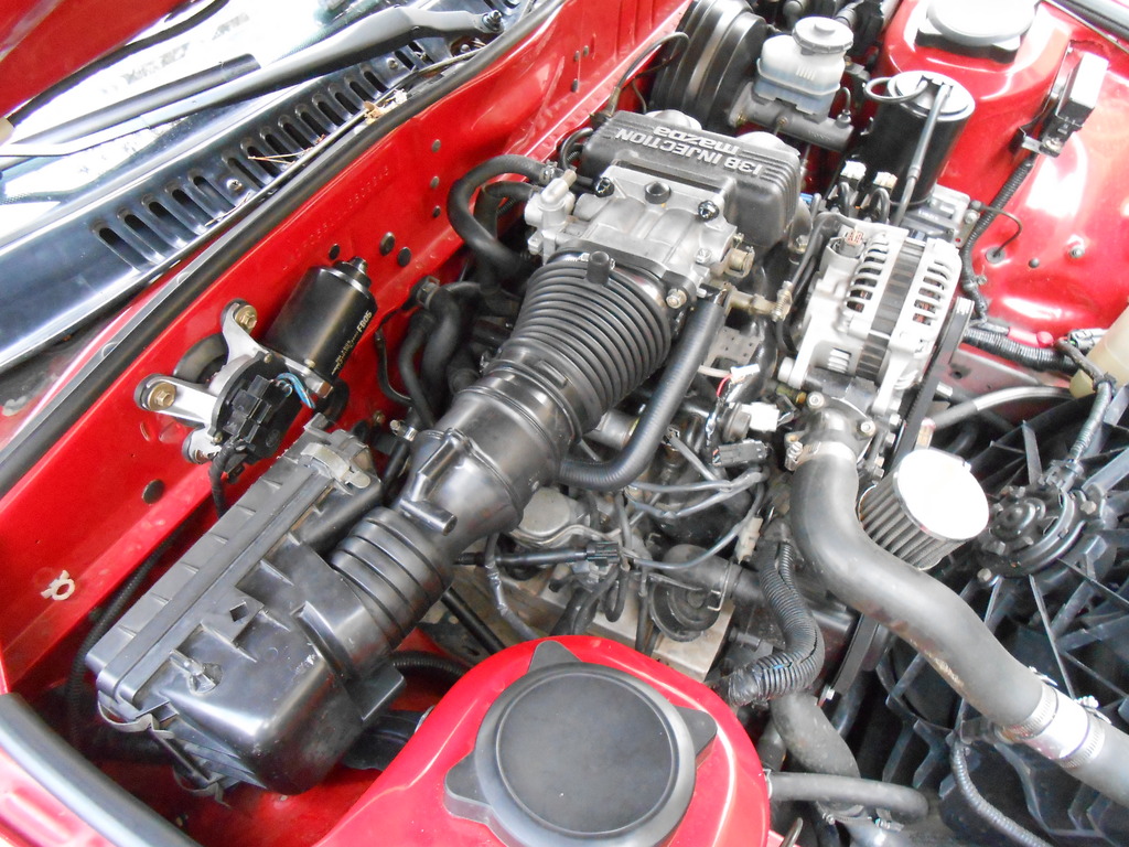
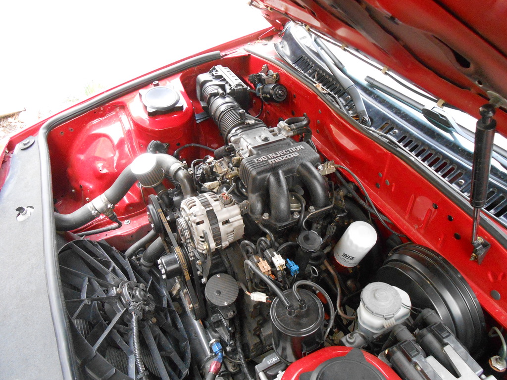
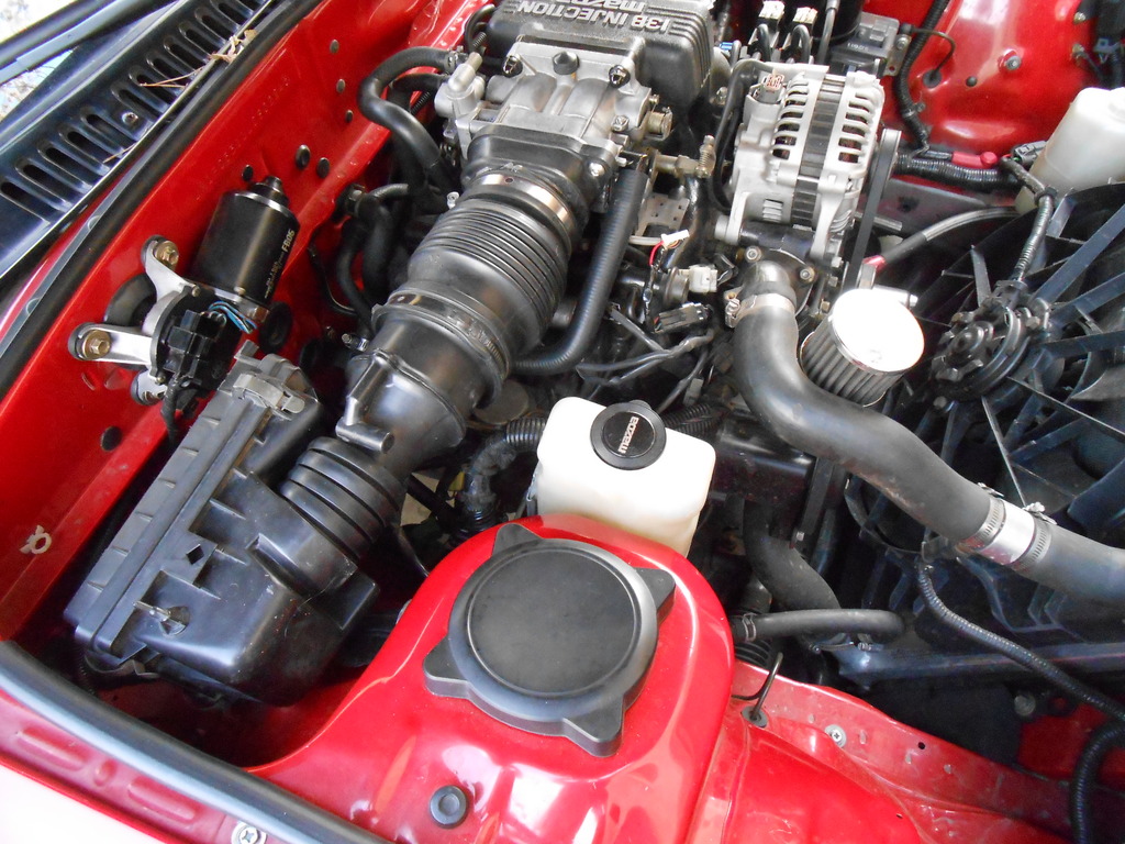
Meanwhile, here's an overview of the bay:
As expected, half of the junkyard was an ankle deep lake (and me without my waders!) and the other half was a treacherous morass but I soldiered through the first world inconvenience and after a hour and a half, scored a reasonable facsimile of what I envisioned.
Version #1 works perfectly but the glue joint is a nagging worry, one I'd like eliminated.
So, can the need for the joint be eliminated?
All it did was attach a round end- easy to slip a tube over but maybe a correctly sized rubber boot could be persuaded to conform to the gently triangle shape of the flange base.
Start with these three parts:
And make this (new one on right):
Before putting it on I thought to show the new metered air arrangement, long as it was exposed:
And it ends up like so:
It's as reasonably close to perfect as $20 and a junkyard will get you.
But I'm afraid the pictures are a lie.
V.1 was dead simple to install, under a minute maybe.
This one is a bit cantankerous.
And by that I mean ridiculously hard.
A shown in the comparison/roof shot above, the boot/clamp fit and seal perfectly.
What they don't do is leave any clearance for the hardware. It's possible to get the studs through the holes but there is zero space for the nuts.
It's a beautiful part that can't be mounted.
Well I'll be danged (or words to that effect).
After some thought, the easiest, least destructive/permanent course was to remove the boot from the flange, bolt the flange onto the throttle body and then try to weasel the boot and clamp on in situ.
This is what yo see above.
What you don't see is the massive leak at the bottom.
I'm pretty sure I'm going to have to remove the dynamic chamber from the exten mani and work with the intake off the car. The boot requires a lot of finessing to get it on right and there's no room or good sightline in position.
And if you're wondering why I don't pull just the throttle body, well, the boot is such a large diameter that access to the two lower nuts is gone.
The hits just keep coming.
Reasonably confident it can be properly assembled in this manner and I'm pleased enough with the look that I'm willing to invest the extra 10-20 minutes in the attempt.
But...and this is kind of a biggie...even if it does work out, adding time to the "normal" maintenance of the car violates a cardinal precept of the Because Streetcar! ethos and I'm not sure how I feel about that.
Assuming assembly success tomorrow, I can continue to explore better adaptor options with the complete spare setup I now have and with luck, come up with a part that better fulfills all the desired features.
Meanwhile, here's an overview of the bay:
04-19-15, 07:34 PM
#1833
MECP Certified Installer
I love your junk yard escapades clokker. Get that new setup fresh air through the cowl already!
Finally upgraded my computer and ditched the peltier setup...
EVGA GTX 960 that is superclocked...I super clocked it some more!
Gigabyte 990FXA-UD3 motherboard. Not enough slots for my liking but it is an overclocking king!
AMD 4350FX Black edition processor. More than 4 cores is pretty much a fools game these days as the 4 core processor out performs the 6 and 8 core variants due to its clock speed. Maybe when when multi threading becomes mainstream.
I overclocked it my new processor by a gigahert (4.4ghz) and it just screams on the stock AMD cooler. I still have my old case with the server fans and stuff, so I am sure that helps. I plan on upgrading the CPU cooler and pushing the dog harder.
04-20-15, 09:02 AM
#1834
I was talking computers with a friend on Sat. and we've both decided that our next pc's would be AMD based. Intel has gotten absurdly expensive and they change things every six months, there's no platform stability at all.
Just get a browser on the screen and I'm happy.
I spent all night grappling with the intake problems and may have come up with a solution.
The main issue right now is that when assembled, the intake cannot be mounted on the throttle body studs. Actually, it will go over the studs but there's no room for nuts.
*I can wait as you insert "she said" jokes at your leisure...*
Finished? Good.
So, if studs/nuts are the problem, get rid of 'em.
I'll pull the studs from the throttle body and use 8mm phillips head screws instead.
The round low profile head won't interfere with the boot and clamp (put the screws through the flange first, then install boot/clamp over them) and don't require the clearance that a nut/socket do...there should be enough space for a screwdriver shaft.
I'll still have to loosen the dynamic chamber (but not remove anything) so the throttle body can be tilted up for clearance above the secondary fuel rail, but that's a small price to pay and easier than the alternative.
I'm hopeful this will work.
I should mention that none of this strife surprises/disappoints me.
My experience with previous harebrained ideas has proven that the closer you get to completion, the weirder and more unexpected the problems become.
Sometimes you eat the bear, sometimes the bear ***** in the woods...it's the great circle of life.
And yes jj, the lure of cowl induction is strong.
After two junkyard trips specifically seeking airboxes, I don't think anything OEM is going to work and the whole thing would have to be fabbed from scratch. As I've worked on the mounting flange, I can't help but envision various ways to go about it but really need to solve the flange issue before seriously thinking about the box.
It'll percolate in the background and something will gell.
04-20-15, 10:12 AM
#1836
Moderator
iTrader: (3)
Join Date: Mar 2001
Location: https://www2.mazda.com/en/100th/
Posts: 30,905
Received 2,648 Likes
on
1,874 Posts
I should mention that none of this strife surprises/disappoints me.
My experience with previous harebrained ideas has proven that the closer you get to completion, the weirder and more unexpected the problems become.
Sometimes you eat the bear, sometimes the bear ***** in the woods...it's the great circle of life.
My experience with previous harebrained ideas has proven that the closer you get to completion, the weirder and more unexpected the problems become.
Sometimes you eat the bear, sometimes the bear ***** in the woods...it's the great circle of life.
the bear **** on my turbo oil drains though... the FC is big and the FD is small, and i've got bits of both, but there just isn't an apparent solution.
 04-20-15, 05:45 PM
#1837
Hard to say...maybe $500-750.
Damn bears, Colbert was right.
The "screw" concept (although I actually went with stainless button head allens) worked perfectly. The intake bolted right up, didn't even have to loosen the manifold.
Win!
Tiger blood!
Car ran like poop.
Let me amend that, she ran fine over 2k rpm, the bottom fell out below.
Swapped AFMs but that didn't help.
Disconnected the airbox, no joy.
Swapped to the first adaptor, everything hunky dory.
Either there is still a big air leak as the flange meets the boot (unlikely but possible) or there is something about the internal dynamics that ***** with airflow at low intake speeds. Either way, I'd replaced the other variables- for whatever reason, that setup wasn't gonna work.
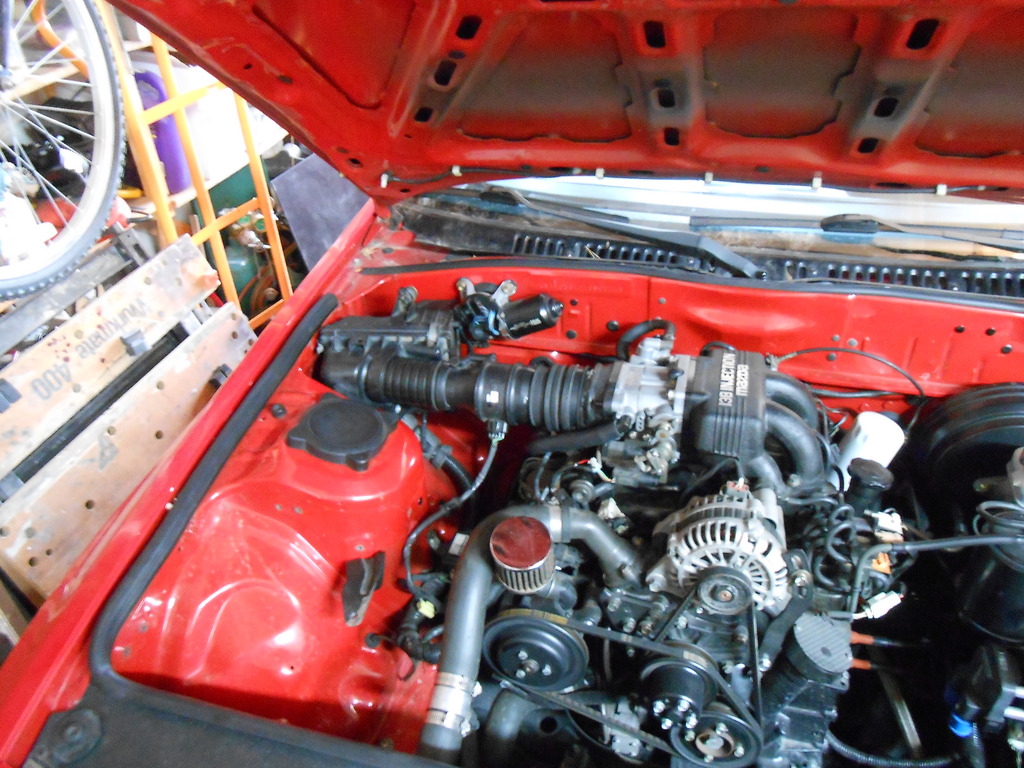
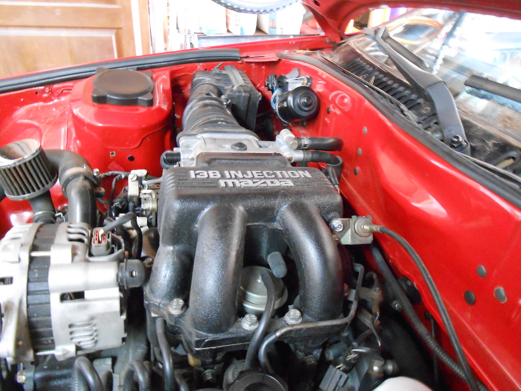
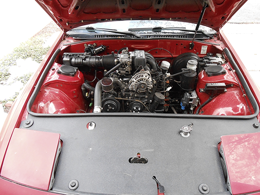
Back to the glued piece (which is holding up well) and revamped boots to get what I hope will be a fairly permanent install:
Runs great like this.
Now to get the washer reservoir back in service.
this is completely true. i ate the bear last week, i bought a new intercooler, which didn't come with mounting brackets, and its big. to my complete surprise the 3 random brackets i had laying around got the thing to go right in, and it fits perfectly.
the bear **** on my turbo oil drains though... the FC is big and the FD is small, and i've got bits of both, but there just isn't an apparent solution.
the bear **** on my turbo oil drains though... the FC is big and the FD is small, and i've got bits of both, but there just isn't an apparent solution.
The "screw" concept (although I actually went with stainless button head allens) worked perfectly. The intake bolted right up, didn't even have to loosen the manifold.
Win!
Tiger blood!
Car ran like poop.
Let me amend that, she ran fine over 2k rpm, the bottom fell out below.
Swapped AFMs but that didn't help.
Disconnected the airbox, no joy.
Swapped to the first adaptor, everything hunky dory.
Either there is still a big air leak as the flange meets the boot (unlikely but possible) or there is something about the internal dynamics that ***** with airflow at low intake speeds. Either way, I'd replaced the other variables- for whatever reason, that setup wasn't gonna work.
Back to the glued piece (which is holding up well) and revamped boots to get what I hope will be a fairly permanent install:
Runs great like this.
Now to get the washer reservoir back in service.
04-20-15, 11:12 PM
#1838
Moderator
iTrader: (3)
Join Date: Mar 2001
Location: https://www2.mazda.com/en/100th/
Posts: 30,905
Received 2,648 Likes
on
1,874 Posts
washer bottle solved! http://garage036.web.fc2.com/diy/washer2/washer2.html
04-21-15, 11:28 AM
#1839
washer bottle solved! http://garage036.web.fc2.com/diy/washer2/washer2.html
A little.
The old setup was specifically/intentionally engineered to fit in the exact space now occupied by the intake, so the trick will be seeing where else it may be sited without too much trouble.
We'll see how that goes in a while.
Meanwhile, today will be the first totally cold start up with the new gear in place...I expect no trouble but that same cavalier attitude has tripped me up before, so optimism is tempered by caution.
It would be embarrassing if (essentially) changing the airfilter lead to Fiery Death!.
04-21-15, 06:14 PM
#1840
Today's test drive ended up being a trip to the yard.
The car drives great.
Wasn't really sure what I was looking for, so I was skimming along waiting for something to catch my eye. And something did.
This is the rad overflow from a Honda Accord and it is unique/rare for two reasons:
-Most plastic tanks are molded to fit in odd nooks and crannies and make no sense once removed from the original spot. This one is a basic, regular shape that is much easier to locate without being obviously wrong/not original.
-In the same vein (and for the same reason), most tanks slot into some other plastic part (commonly the battery box or fan shroud) and are difficult to mount another way.This one not only had a separate metal bracket that bolted on but the bracket was not weird and spidery...it was nice and simple.
Tonight I'll clean it up and install the pump.
And yes, I tried multiple locations before settling on this.
The primary reason for this spot is my wiring reaches it, so it's plug-n-play, easy peasy.
This is no small advantage. The hose length is minimized, if that's any big deal.
And it's easy to see the fluid level.
I did consider hiding it up front under the nose cover but that seemed needlessly complex for only a bit of cosmetic gain.
I can always claim that the proximity to the exhaust manifold heats the fluid in the winter.
Heats it in the summer too, I guess.
So, I've added a feature.
04-21-15, 06:33 PM
#1842
Moderator
iTrader: (3)
Join Date: Mar 2001
Location: https://www2.mazda.com/en/100th/
Posts: 30,905
Received 2,648 Likes
on
1,874 Posts
this may not be a bad thing where you live. my mom has a 2011 Volvo, and its basically been perfect here, but it doesn't handle weather very well. the washer fluid froze, which is a small annoyance, the bigger one was the wipers freezing... and the bigger one than that was the roof leaking.
04-21-15, 06:33 PM
#1843
Junior Member
Join Date: Jan 2015
Location: Arizona
Posts: 33
Likes: 0
Received 0 Likes
on
0 Posts
Looking beautiful! Like how you got the cone filter on there took some thinking it looks like. And sorry you had a super rough day archaphil, hope she forgive you soon 
04-22-15, 10:59 AM
#1844
this may not be a bad thing where you live. my mom has a 2011 Volvo, and its basically been perfect here, but it doesn't handle weather very well. the washer fluid froze, which is a small annoyance, the bigger one was the wipers freezing... and the bigger one than that was the roof leaking.
04-22-15, 12:45 PM
#1845
Moderator
iTrader: (3)
Join Date: Mar 2001
Location: https://www2.mazda.com/en/100th/
Posts: 30,905
Received 2,648 Likes
on
1,874 Posts
the Swedes have a thing called the Vasa, which is frankly awesome. the king (which they still use), had a boat built in the 1600's, and it sank on the test drive. in the 60's they hauled it up to the surface and put it in a museum, so you can see it, and its fantastic. the hilarious part is that the boat is built so badly its in danger of capsizing again, even though its not even on the water.
http://en.wikipedia.org/wiki/Vasa_(ship)
04-22-15, 04:54 PM
#1846
And we have a whole new airbox.
I wasn't even looking (too hard) for one, there were other things I wanted (and found) but this caught my eye, sitting atop a Honda Civic.
The Civic had an intact intake though and this was slightly different, so I think someone was comparing and left this box sitting.
In other words, I have no clue what this is from. I'll pull the number from the filter and that might tell.
Anyway, this box fits the space oddly well and doesn't require major surgery to go in intact.
The inlet is wrong but I think that'll be easily fixed. The outlet (where the AFM joins the box) will require a 90� boot...and I only have one to try, but they are abundant in the yard if I need one.
He says optimistically.
This gets me one step closer to a complete intake swap.
And, apropos of all this Volvo chat...
For a while I've been meaning to look at the air pump, it's making chugging noises and I'd like to see what's what. It's been a while since I've paid it any attention.
So the airpump has been in the back of my mind, nothing definite, just there.
While widget hunting I stopped at a Volvo 960 and right in my face was a very nice electric air pump. I've done zero research and haven't examined the space but this pump looked like a real easy way to start.
Combined with welfare's recent solution to the belt issue when deleting the airpump, this might be my next "big" experiment.
04-22-15, 11:59 PM
#1847
Moderator
iTrader: (3)
Join Date: Mar 2001
Location: https://www2.mazda.com/en/100th/
Posts: 30,905
Received 2,648 Likes
on
1,874 Posts
While widget hunting I stopped at a Volvo 960 and right in my face was a very nice electric air pump. I've done zero research and haven't examined the space but this pump looked like a real easy way to start.
Combined with welfare's recent solution to the belt issue when deleting the airpump, this might be my next "big" experiment.
the FC makes it really easy too, as the TPS test plug is literally the outputs to the two ACV solenoids (and a power), so its a very easy place to get the output, it could literally plug in.
04-23-15, 08:47 AM
#1848
If I use this box I can legitimately run "Type R" stickers and gain some HP.
"Woot" is the appropriate term, I believe.
What/where is this "test plug" you speak of?
Is it green?
As I explained to spectre a few weeks ago, my knowledge of the engine controls is minimal because mine have always just worked and I haven't had to learn anything.
I know what (kinda) goes where but that's it.
04-23-15, 08:56 AM
#1849
MECP Certified Installer
It's from an '88-91 Honda Civic/CRX.
If I use this box I can legitimately run "Type R" stickers and gain some HP.
"Woot" is the appropriate term, I believe.
OK, now you have my attention.
What/where is this "test plug" you speak of?
Is it green?
As I explained to spectre a few weeks ago, my knowledge of the engine controls is minimal because mine have always just worked and I haven't had to learn anything.
I know what (kinda) goes where but that's it.
It has 12v power on it and the other 2 pins go to ground depending on the TPS sensor position.
04-23-15, 09:01 AM
#1850
Moderator
iTrader: (3)
Join Date: Mar 2001
Location: https://www2.mazda.com/en/100th/
Posts: 30,905
Received 2,648 Likes
on
1,874 Posts
OK, now you have my attention.
What/where is this "test plug" you speak of?
Is it green?
As I explained to spectre a few weeks ago, my knowledge of the engine controls is minimal because mine have always just worked and I haven't had to learn anything.
I know what (kinda) goes where but that's it.
the FD is a little more sophisticated, as it turns the ACV off when the air pump is off, and the ACV doesn't seem to pass any air in that state. the FC defaults to the relief position, which is fine i guess.
and the third leg, the Rx8 uses an electric air pump, and it also has an ACV, although its very simple, basically its a fancy check valve