
S5 vacuum routing , need help (pic)


S5 vacuum routing , need help (pic)
i am doing the vacuum routing on a non-turbo S5 currently. i have the vac rack, but nothing is connected and i am having a hell of a time figuring things out.
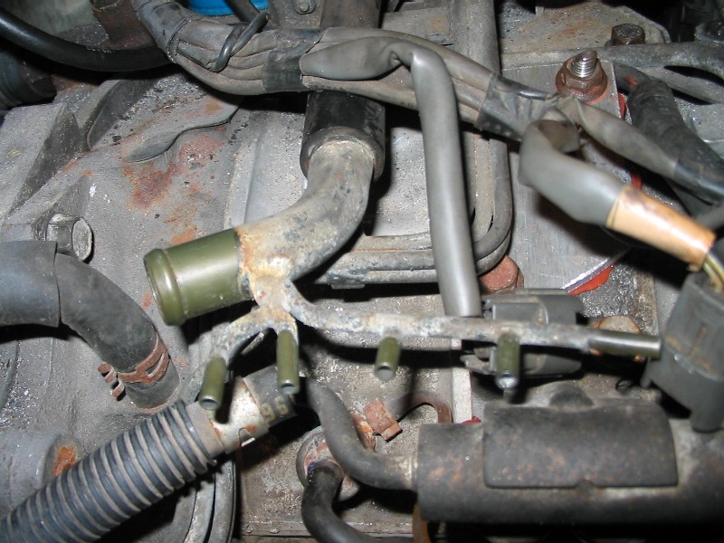
main area of concern right now is in the picture below. if someone can tell me what this is all about, where it goes, that would be great!
main area of concern right now is in the picture below. if someone can tell me what this is all about, where it goes, that would be great!
i mean where those six (the one big one and the 5 smaller nipples) connect to. i don't see it anywhere in the FSM vacuum routing diagram. right now the other end of this vac branch is connected to the accelerated warm up solenoid i believe.
this is what i have figured out so far:
- the big branch goes to a T that is coming from the intake funnel. i don't know where this T is exactly, but i know that the BACV also needs a source from the intake funnel, so i am just assuming there is a T
- FOUR of the small branches are used for the air bleed of the four oil injectors
- the FIFTH branch goes to another T that is for the 2 secondary injector air bleeds
can anyone confirm this??
thanks
NOBODY has any clue, or what? i see 41 views, and no replies, lol
even though it is a very unique vac branch, i will give a little more detail. what you see there is right above the keg, under the UIM (not on at the moment).
in the lower part of the pic you can see the primary fuel rail...
even though it is a very unique vac branch, i will give a little more detail. what you see there is right above the keg, under the UIM (not on at the moment).
in the lower part of the pic you can see the primary fuel rail...
Senior Member
Joined: Sep 2003
Posts: 414
Likes: 0
From: Fort Worth, TX
I took mine out long time ago however if I remember correctly 4 of them go to the oil injectors (99.9% sure). The 5th one.....can't remember.
The big one looks like the one that goes conected to the split air pipe from the exhaust.
That is my guess.
The big one looks like the one that goes conected to the split air pipe from the exhaust.
That is my guess.
Carter 2.0
Joined: Jun 2004
Posts: 6,262
Likes: 7
From: Irvine Ca.
Sorry I diddn't come on line yesterday coldfire. The 5 small ones all hook to your MOP injector nipples. There is one just below those 5 on your pic. There are 4 mop lines that go below and hook (of course) the the MOP (or OMP) Don't mess with those but follow them up to your intake. The hook to a banjo and on TOP of that bamnjo (that leads into the actual intake) is another nipple.......that needs vacuum and that is where 4 of the 5 small ones go. Like I said in your pic there is one of the 4 with a black vacuum hose on it. just rout it upwards and hook it into the best fitting one.
The 5th and the large hose, I can't remember just now.
More to follow. I have pull my car around to my Garage.
The 5th and the large hose, I can't remember just now.
More to follow. I have pull my car around to my Garage.

The fifth of the small lines goes to a nipple on the block side of the LIM -right in the centre. It is the air bleed for the primary injectors - the passage goes through the LIM, the gasket and splits into two passages into the block.
The large tube receives the air supply from the large flexible air intake tube.
If this pic attaches, never mind the green marking, the red loop circles the 5th air bleed.
curtis
'86 GXL autox'r (VDI swap)
The large tube receives the air supply from the large flexible air intake tube.
If this pic attaches, never mind the green marking, the red loop circles the 5th air bleed.
curtis
'86 GXL autox'r (VDI swap)
Trending Topics
thanks a lot guys! i have it all figured out. i did a little more searching on the forum and have found some good stuff. i'll be making a thread sometime containing every piece of S5 non-turbo vacuum routing information i have.
last question i have is about the BACV and the main large line for the branch we are talking about here. do they both share a line coming from the flexible intake funnel? if so, does anyone have a picture of this?
thanks again!
last question i have is about the BACV and the main large line for the branch we are talking about here. do they both share a line coming from the flexible intake funnel? if so, does anyone have a picture of this?
thanks again!
ok, i am on the home stretch here. i just got a few things to figure out:
1) where does air line for the BACV go to (i think i know, but want to confirm)?
2) where does the large nipple on the dynamic chamber go to? (marked w/ green tape)
3) where does the line for the AWS solenoid valve go to (marked w/ green tape)
4) where does the hose coming from the BIG line in the branch, seen in my first post, go to? (also marked w/ green tape)
Former Moderator. RIP Icemark.
Joined: Apr 2001
Posts: 25,896
Likes: 24
From: Rohnert Park CA
Originally Posted by coldfire
ok, i am on the home stretch here. i just got a few things to figure out:
1) where does air line for the BACV go to (i think i know, but want to confirm)?
2) where does the large nipple on the dynamic chamber go to? (marked w/ green tape)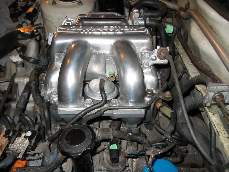
1) where does air line for the BACV go to (i think i know, but want to confirm)?
2) where does the large nipple on the dynamic chamber go to? (marked w/ green tape)
3) where does the line for the AWS solenoid valve go to (marked w/ green tape)
Senior Member
Joined: Sep 2003
Posts: 414
Likes: 0
From: Fort Worth, TX
#2 From the dynamic chamber to the purge valve. (Place a hose between the 2 green tapes shown on image 1)
#1 from the back to a nipple on the air intake hose between the air filter and throttle body
#1 from the back to a nipple on the air intake hose between the air filter and throttle body
Last edited by stacher; May 16, 2005 at 11:39 PM.
