When you click on links to various merchants on this site and make a purchase, this can result in this site earning a commission. Affiliate programs and affiliations include, but are not limited to, the eBay Partner Network.
I'm sure this question has been answered a million times, but I haven't been able to find an answer.
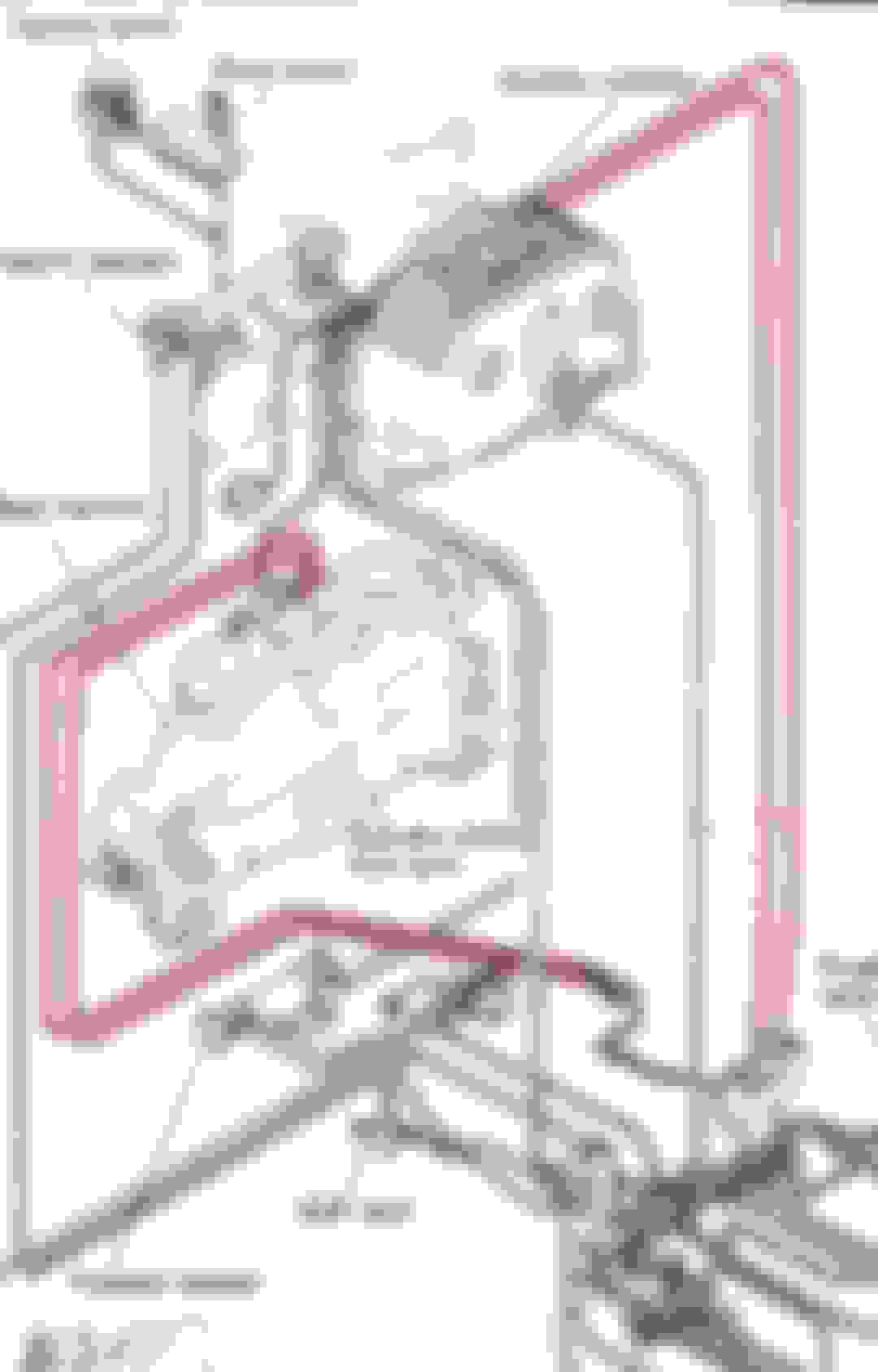
I recently deleted the rats nest on my car. Along with that, a lot of vaccum lines came out. I'm trying to determine which vaccum ports are for the injector air bleed.
Are the highlighted lines below correct? If so, can I just route these vac lines directly to the dynamic chamber?
You do need those two highlighted lines, but not for the reason you think.
There are exactly five vacuum lines you "need" on the dynamic chamber.
One is the forest green one that is the middle nipple on the front. This is the injector air bleed you mentioned. It should always be connected, makes a big difference in idle quality.
One is the large molded one (topmost nipple on the front) that provides air to the OMP injectors. Clear on the front diagram.
One is the light green one you can see on the end of the dynamic chamber. This is the vacuum signal for the fuel pressure regulator. The orange solenoid it runs through is supposedly to help hot starting. I've noticed no difference with / without solenoid but you should keep it anyways imo. In the diagram it changes to purple post-solenoid.
Then the two that you highlighted on the back, red and forest green. Those are for the PCV system. If you have an oil catch can then you may use a different setup, but stock the bottom one is for the vacuum signal (small bottom nipple on the PCV valve), the top one is for the outlet on the PCV valve (top small nipple), and the large bottom nipple on the PCV valve goes to the oil filler neck port. Then the smaller port directly below on the middle iron goes to the hardline on the firewall that comes from the charcoal canister.
EDIT: Also, the way you've highlighted them is not the way they actually run. They do run down to the spider in stock applications, but the come out nearer the PCV valve. They do not run along to the back of the LIM as highlighted. In your case, with the spider deleted, you can just run straight hose and make a small bracket for the PCV. Unless you have a catch can set up already, in which case you can cap them and forget about it.
EDIT: Also, the way you've highlighted them is not the way they actually run.
i've found that the diagram just lacks resolution, so i'll take the hose off on each end and make sure its connected (more of a problem on the turbo and S5 NA, where there are two racks) and then i get to make sure its in the right places too.
also i've seen racks that have plugged pipes, and not sure with what, but i was able to clean em out
You do need those two highlighted lines, but not for the reason you think.
There are exactly five vacuum lines you "need" on the dynamic chamber.
One is the forest green one that is the middle nipple on the front. This is the injector air bleed you mentioned. It should always be connected, makes a big difference in idle quality.
One is the large molded one (topmost nipple on the front) that provides air to the OMP injectors. Clear on the front diagram.
One is the light green one you can see on the end of the dynamic chamber. This is the vacuum signal for the fuel pressure regulator. The orange solenoid it runs through is supposedly to help hot starting. I've noticed no difference with / without solenoid but you should keep it anyways imo. In the diagram it changes to purple post-solenoid.
Then the two that you highlighted on the back, red and forest green. Those are for the PCV system. If you have an oil catch can then you may use a different setup, but stock the bottom one is for the vacuum signal (small bottom nipple on the PCV valve), the top one is for the outlet on the PCV valve (top small nipple), and the large bottom nipple on the PCV valve goes to the oil filler neck port. Then the smaller port directly below on the middle iron goes to the hardline on the firewall that comes from the charcoal canister.
EDIT: Also, the way you've highlighted them is not the way they actually run. They do run down to the spider in stock applications, but the come out nearer the PCV valve. They do not run along to the back of the LIM as highlighted. In your case, with the spider deleted, you can just run straight hose and make a small bracket for the PCV. Unless you have a catch can set up already, in which case you can cap them and forget about it.
So, just to clarify:
The blue line is for the FPR vaccum, red is for PCV, and the yellow line is the air bleed?
In the FSM, the yellow line goes to the front of the manifold, but in the diagram you sent, it routes to the back. Which is the correct routing for this line?
So, just to clarify:
The blue line is for the FPR vaccum, red is for PCV, and the yellow line is the air bleed?
In the FSM, the yellow line goes to the front of the manifold, but in the diagram you sent, it routes to the back. Which is the correct routing for this line?
Yes, blue is for the FPR (solenoid optional).
Red is for PCV, but without the spider you need to run them directly to it.
The correct routing for the yellow line (air bleed) is the one going to the front of the manifold, down directly between the primary intake runners.
I'm not sure what's going on with the one running to the rear in some diagrams. It also says "sub zero starting fluid valve" which is actually on the upper intake. So something is up with those diagrams.
Got it. So the yellow line is incorrect in the diagram I just sent? It's supposed to route on the side of the manifold facing the engine down between the OMP injectors and primary injectors?
Got it. So the yellow line is incorrect in the diagram I just sent? It's supposed to route on the side of the manifold facing the engine down between the OMP injectors and primary injectors?
Correct, it should go down from the dynamic chamber to the side of the manifold facing the engine between the OMP injectors and primary injectors.
Correct, it should go down from the dynamic chamber to the side of the manifold facing the engine between the OMP injectors and primary injectors.
Got it! Thank you.
Not sure why the FSM doesn't specify that. On the page after that diagram, it makes mention of the air bleed, but it's not labeled. Also strange how the diagram itself is different
Bumping this thread and hoping @WondrousBread can re-visit this because I'm a little confused.
Much like the OP, i was wondering where the line went for the S4 NA injector air bleed. I have the FSM and in it, it shows that the line APPEARS to go towards the FRONT of the lower intake manifold facing away from the engine. See image below. I thought the red square highlighted below was for the injector air bleed...but that seemed like an odd way to route a vacuum line.
Then i noticed a nipple right in front of the primary injectors...THAT seems to be the air bleed nipple for the primary injectors...
My question then becomes...what is the nipple in the picture (red square) that is facing away from the engine for? Sub - zero? Are there two air bleed nipples?
The image OP is using is different than the S4 engines I've seen. Not sure if it's for a different destination market perhaps.
You've correctly identified the primary injector air bleed in green. The nipple highlighted in red is for the stock MAP sensor. You can just cap it if not in use.
EDIT: I'm actually noticing now that even in the diagram I provided earlier in this thread, there are differences from the USDM / Canadian S4. The main thing I notice is the sub-zero valve is in the wrong place on both diagrams, and they both show some sort of valve teed off of the MAP sensor, which I don't think exists. OPs diagram is also missing the primary air bleed. Moral of the story is to always be wary of diagrams I suppose.
Last edited by WondrousBread; Feb 21, 2026 at 06:56 AM.
The image OP is using is different than the S4 engines I've seen. Not sure if it's for a different destination market perhaps.
You've correctly identified the primary injector air bleed in green. The nipple highlighted in red is for the stock MAP sensor. You can just cap it if not in use.
The MAP sensor lives on the passenger side strut tower. Little black box, mounts with a single tab, four pin connector.
I think the service manual calls it something else
on my 88 na the black plastic thing is called a Boost Sensor. I just happened to be trying to locate where the vacuum line from the sensor goes. It reaches the nipple on the front of the lower intake manifold.
I have a problem with the two smaller vacuum lines from the purge valve.
I took apart a broken purge valve, there is just a spring pushing on a rubber diaphragm. the rubber seals the top from the bottom completely.
With vacuum applied to the top port on the purge valve, it pulls the diaphragm up to uncover the port on the bottom part of the valve.
This opens a path for the bypass gases and the evaporation canister fumes that leads to a small opening at the top of the primary throttle bore.
This is the way the gasses get pulled into the dynamic chamber and into the engine intake.
So, Mister Fume leaves the engine through the large hose in the bottom of the valve, once the small port on the bottom is uncovered by high vacuum in the top part of the valve
it travels through the small hole in the bottom, this is the port that the bottom small vac line goes to.
I noticed that the actual opening in the plastic is necked down to a smaller diameter than the hose size.
Restricting the flow of gasses through the valve. The pull on the fumes come from the small hole in the throttle bore.
The fumes get pulled by the venturi effect. As the intake air flows over the small hole it pulls the fumes out. No vacuum is used!
So as long as the diaphragm is held away from the bottom ports the fumes make their way through the throttle bore opening.
It appears that the the top port needs a vacuum signal to pull against the spring pressure.
Both the small and large ports on the bottom need the pull on the small opening in primary bore when the engine is running.
This moves the bypass gasses and the storied gas fumes from the fuel tank into the engine to be burned.
The vacuum signal comes from the lower of the two ports on the dynamic chamber.
If you look at the thick black part that goes between the throttle body and the dynamic chamber
you will notice that the primary bore has two openings in it. These are the only vacuum ports used on the plate.
With the throttle body removed and the black plate still in place on the chamber, I blew through a hose attached to the
bottom nipple on the chamber. The air flowed out of the opening that is in the plate bore.
High vacuum signal will pull the purge valve open and the gasses will start to flow from the bottom of the valve. Throttle plate closed
Low vacuum signal will not let the gasses out. Throttle open.
The amount of vacuum signal lets different amounts of blow-by gasses flow into the intake.
You really don't want the extra gasses in while you are at idle.
Now it gets weird, when I blew air into the upper nipple the air came out through the hole in the middle between the both bores on the plate!
I found a corresponding hole on the back of the throttle body.
When I blew air into this hole it only came through the small hole in the primary throttle bore.
The top port on the purge valve gets its vacuum from the lower port on the chamber.
The bottom small port allows the gasses to enter the intake through the upper port on the chamber.
This is the only way for the system to hold gas vapors overnight in the evap canister, then pull the vapors out into the engine to be burnt.
This is also the only way for those nasty blow-by gasses to get pulled from the engine while it is running.
This is just the opposite that the diagrams show in this thread.
So please let me know what you think.
Last edited by gsmithrx7; May 1, 2026 at 09:41 PM.
Reason: looked at the diagrams in this thread