
Progress Of My Turbo/NA/Bridgeport Project (Project Tina)

Thread Starter
Joined: Feb 2001
Posts: 29,798
Likes: 128
From: London, Ontario, Canada
Progress Of My Turbo/NA/Bridgeport Project (Project Tina)
It's time once again for another update on my ongoing turbo-NA-bridgeport project. The previous thread in this series can be found here. Progress over the last few months has seemed slow due to not having large amounts of continuous time to work on things. But in reality, actually a lot has been accomplished. Many of these tasks are small, but in a project such as this, the meat of what needs to be done are small side jobs in between the large chunks. Thus, these pictures probably aren't anything ground breaking or as interesting as an engine assembly. Most of them deal with things outside the engine bay. While these aren't as glamorous as porting or engine assembly, they are necessary parts of the groundwork that supports the larger part of what is taking place.
That said, I don't think anyone will find this post boring. As always, there are a few neat details that you won't see anywhere else. All of this has brought me to what will take place very soon (not in this thread): after almost three years, the engine will be reinstalled in the car.
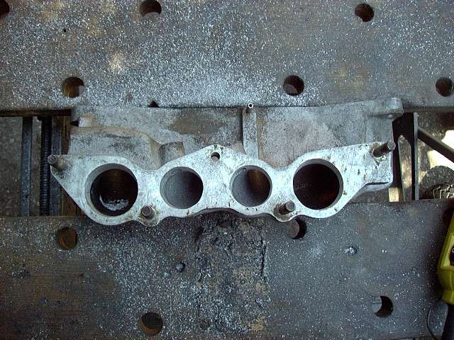
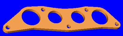
So, to pick up where we last left off, here's the lower intake after some quick porting. Since it was already being heavily modified, I figured that I might as well port it. The gains are very small, and it's absolutely not worth doing unless you already have the intake removed and are very bored.
With the engine moved out of the basement and into the garage, it was time to install the oil pan. First, the oil pressure regulator was installed, and then the pickup. This oil regulator has been modified by shimming. Two M5 flat washers were placed inside the bottom of the piston. This increases spring tension, and thus oil pressure. Two washers should make for about 100 PSI of pressure.
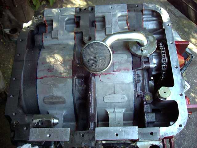
Next, the gasket and sealant were installed. On top of that, a Racing Beat baffle plate was installed. This plate prevents the oil from sloshing away from the pickup during deep, high speed turns. A must for anyone intending to autocross or track the car.
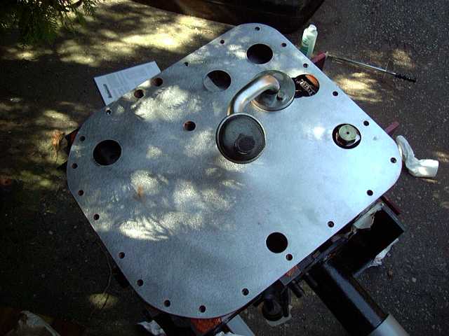
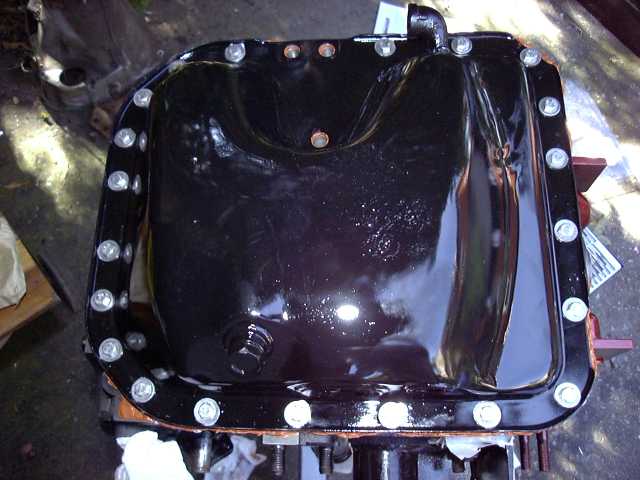
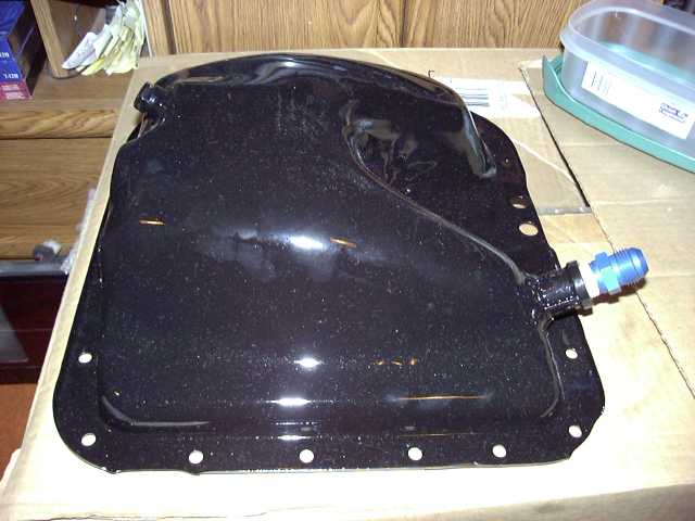
And then the oil pan is installed, with another gasket between it and the baffle. Notice the stainless steel bolts, as well as the wide washers. The washers help spread out the force from the bolt heads, thus going a long way to preventing oil leaks. I had to manually cut each of these bolts to size. Anytime stainless hardware is used, anti-seize MUST be applied to the threads. Otherwise, the stainless will weld itself to the aluminum of the engine.
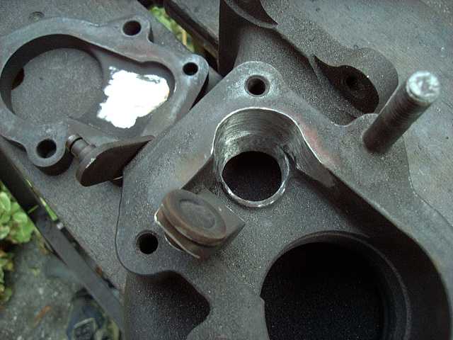
With the oil pan installed, it was time to do a little porting on the turbo wastegate.
That said, I don't think anyone will find this post boring. As always, there are a few neat details that you won't see anywhere else. All of this has brought me to what will take place very soon (not in this thread): after almost three years, the engine will be reinstalled in the car.
So, to pick up where we last left off, here's the lower intake after some quick porting. Since it was already being heavily modified, I figured that I might as well port it. The gains are very small, and it's absolutely not worth doing unless you already have the intake removed and are very bored.
With the engine moved out of the basement and into the garage, it was time to install the oil pan. First, the oil pressure regulator was installed, and then the pickup. This oil regulator has been modified by shimming. Two M5 flat washers were placed inside the bottom of the piston. This increases spring tension, and thus oil pressure. Two washers should make for about 100 PSI of pressure.
Next, the gasket and sealant were installed. On top of that, a Racing Beat baffle plate was installed. This plate prevents the oil from sloshing away from the pickup during deep, high speed turns. A must for anyone intending to autocross or track the car.
And then the oil pan is installed, with another gasket between it and the baffle. Notice the stainless steel bolts, as well as the wide washers. The washers help spread out the force from the bolt heads, thus going a long way to preventing oil leaks. I had to manually cut each of these bolts to size. Anytime stainless hardware is used, anti-seize MUST be applied to the threads. Otherwise, the stainless will weld itself to the aluminum of the engine.
With the oil pan installed, it was time to do a little porting on the turbo wastegate.
Thread Starter
Joined: Feb 2001
Posts: 29,798
Likes: 128
From: London, Ontario, Canada
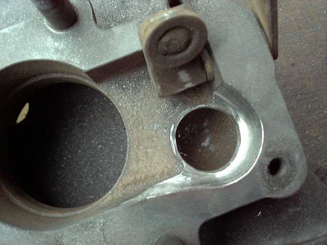
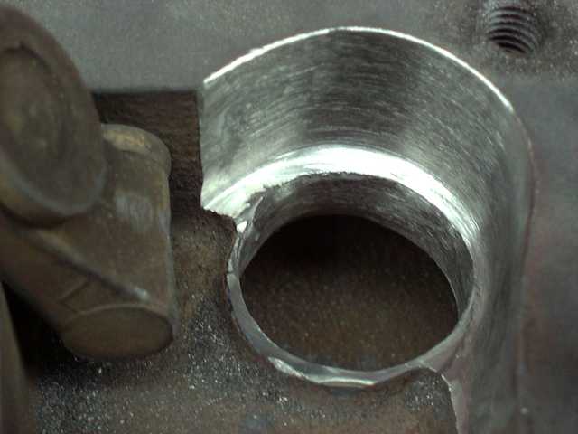
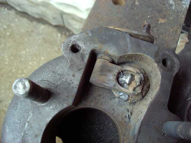
You can see how the wastegate orifice is becoming much larger then the flapper door itself. This is the ONLY way to effectively port the wastegate. Also, relief has been cut into the backing plate to allow the wastegate to swing open much wider.
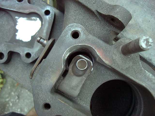
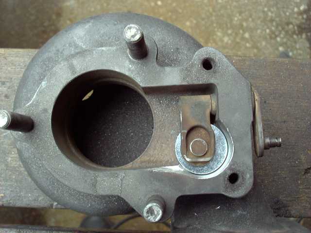
A very dark interior view of that wastegate.
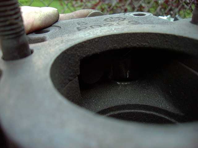
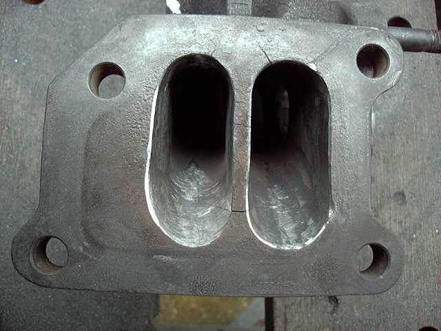
Since the turbo is disassembled, might as well port those exhaust runners. Here, you see the smaller twin-scroll runner is now ported as large as the "main" runner.

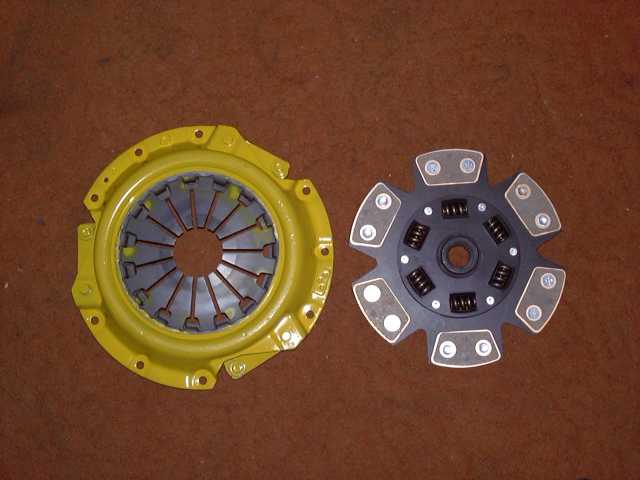
My clutch came about this time. Purchased from CP Racing. It's just a nice looking clutch. Also, much stronger then stock.
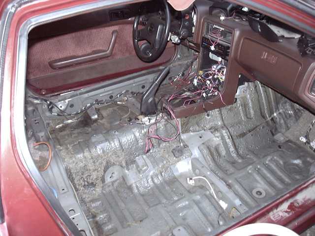
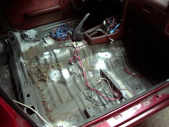
For a change, it's time to work inside the car. The carpets are being replaced, the door panels recovered, and the seats recovered. First step was to remove the carpet, seats and console.
A very dark interior view of that wastegate.
Since the turbo is disassembled, might as well port those exhaust runners. Here, you see the smaller twin-scroll runner is now ported as large as the "main" runner.
My clutch came about this time. Purchased from CP Racing. It's just a nice looking clutch.
Also, much stronger then stock.For a change, it's time to work inside the car. The carpets are being replaced, the door panels recovered, and the seats recovered. First step was to remove the carpet, seats and console.
Thread Starter
Joined: Feb 2001
Posts: 29,798
Likes: 128
From: London, Ontario, Canada
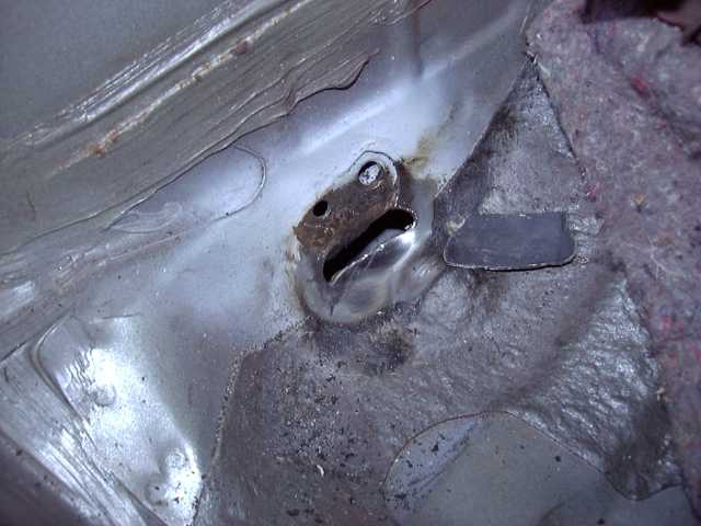
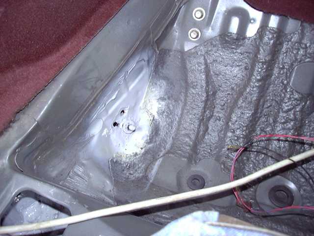
While pulling apart the storage bin areas, I made a horrible discovery: cancer! This was found on the drivers side.
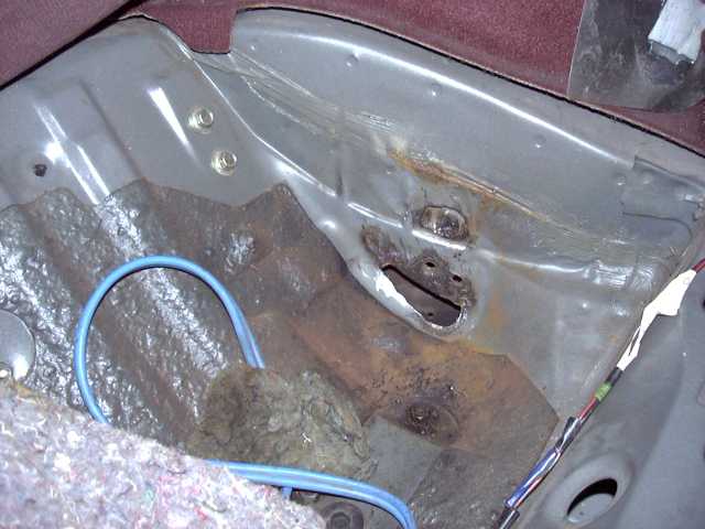
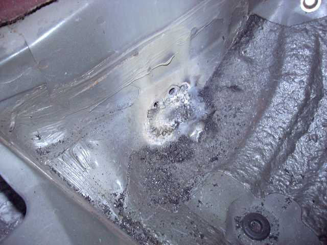
More on the passenger side. Clearly, the bolt holes for the rear seats have allowed moisture to get trapped between the frame rail and body in an unprotected area. So it rotted through.
A few other minor areas of concern were found. Any surface rust was ground off then primed to prevent further corrosion.
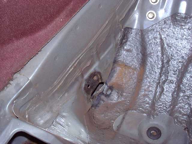
The only way to fight cancer is to cut it out. Rotted metal must be cut away to expose good metal, then a patch panel made and welded in. Below shows the large hole left after cutting the cancerous skin away, and the new panel of virgin steel.
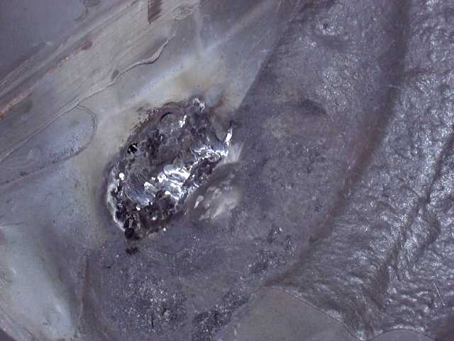
The new panel is welded in. Welding thin sheet metal takes patience, and a thin wire. Unfortunately, I only had 0.035" wire on hand, so there was some frustration involved.
More on the passenger side. Clearly, the bolt holes for the rear seats have allowed moisture to get trapped between the frame rail and body in an unprotected area. So it rotted through.
A few other minor areas of concern were found. Any surface rust was ground off then primed to prevent further corrosion.
The only way to fight cancer is to cut it out. Rotted metal must be cut away to expose good metal, then a patch panel made and welded in. Below shows the large hole left after cutting the cancerous skin away, and the new panel of virgin steel.
The new panel is welded in. Welding thin sheet metal takes patience, and a thin wire. Unfortunately, I only had 0.035" wire on hand, so there was some frustration involved.
Thread Starter
Joined: Feb 2001
Posts: 29,798
Likes: 128
From: London, Ontario, Canada

The welds are ground down. Truthfully, this area didn't have to be perfect, since it is going to be covered by a battery box. But it does have to be presentable.
A similar panel was made for the driver side. The patch was actually quite a lot larger in that area. More care was taken on this side, since in theory, someone at some point might see it.
But it doesn't need the effort necessary when working on a visible exterior panel. The black mark you see is actually the undercoating that made it's way through the bolt hole and oozed over the primer.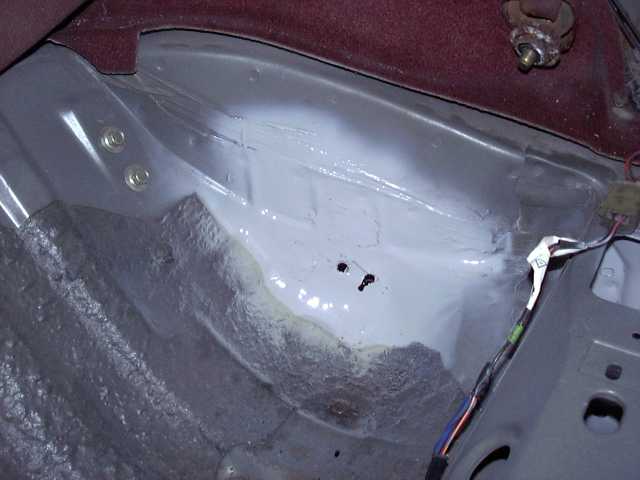
The passenger side patch is finished. A bolt was welded to the panel to provide a good ground for the battery. But this bolt is actually going to be removed since it's in the way of the battery box.
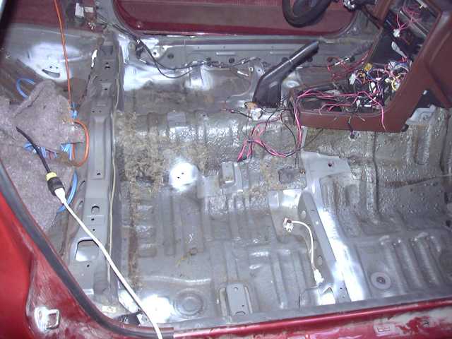
After the cancer treatments, the remaining interior touch ups were made and some of the wiring is being laid in place.
Thread Starter
Joined: Feb 2001
Posts: 29,798
Likes: 128
From: London, Ontario, Canada
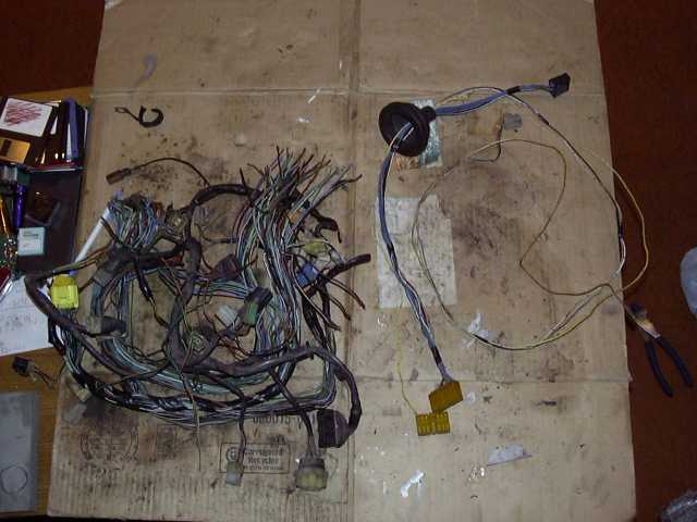
Since I am ditching the stock ECU in favor of the Microtech LT-8, most of the engine wiring harness is no longer needed. The only thing necessary to keep are the leads to the wiper motor, alternator and coolant sensor. On the right is what's left of the stock wiring harness. On the right is all the unneeded stuff. I was amazed at the condition my stock wiring harness was in. Underneath the crusty exterior, the inner wires looked as if they had just come from the factory. Goes to show you that the Mazda wiring, while somewhat unique, is high quality stuff.
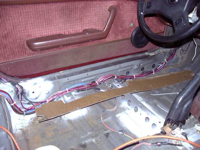
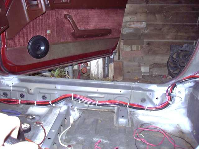
Wires were then run down the driver side sill for the audio and MP3 player. In this bundle, power for both the amp and MP3 player, speaker wires from the amp, signal wires to the amp, and audio to/from the MP3 player. Also a few other misc signal wires. Of course, this bundle tucks neatly underneath the fiberboard cover. It's a cardinal rule to never mix power and signal wires, but in this case, all the audio signal wires are heavily shielded, so there will be no problems.
The passenger side wiring was done next. Shown here are the two thick (power and ground) battery cables, the rear passenger speaker wire, and the power and ground for the fuel pump. I prefer to ground my battery to multiple locations. This means running a large ground wire from the battery to the car in several places, and ultimately to the engine as well. Multiple GOOD grounds are vitally important. The fuel pump also has it's own separate ground, as will the ignition box and Microtech. This the only way to assure clean power to these important components.
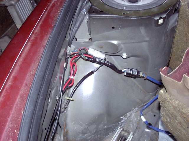
Starting the fuel pump wiring at the pump. I'm going to be crucified for not using sealant-filled heat shrink, but I honestly just ran out. Next time I am in that area, I will correct my sloppy work.
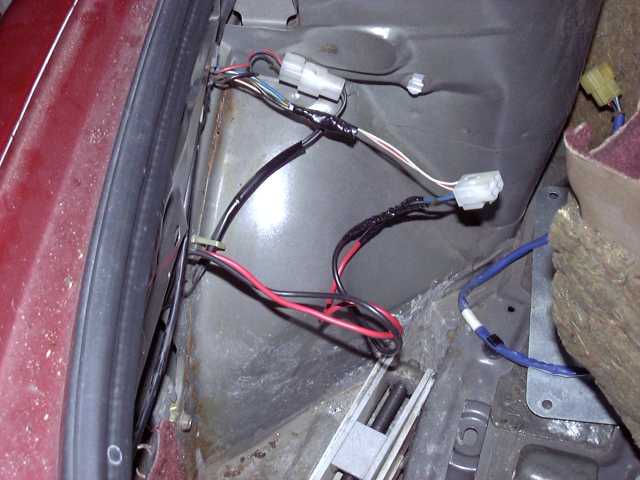
And the fuel pump wiring is finished and tied off. Also notice that the harness plug has also been taped. I've seen these break, so any little bit of extra strength is a good thing in my books.
I was amazed at the condition my stock wiring harness was in. Underneath the crusty exterior, the inner wires looked as if they had just come from the factory. Goes to show you that the Mazda wiring, while somewhat unique, is high quality stuff.Wires were then run down the driver side sill for the audio and MP3 player. In this bundle, power for both the amp and MP3 player, speaker wires from the amp, signal wires to the amp, and audio to/from the MP3 player. Also a few other misc signal wires. Of course, this bundle tucks neatly underneath the fiberboard cover. It's a cardinal rule to never mix power and signal wires, but in this case, all the audio signal wires are heavily shielded, so there will be no problems.
The passenger side wiring was done next. Shown here are the two thick (power and ground) battery cables, the rear passenger speaker wire, and the power and ground for the fuel pump. I prefer to ground my battery to multiple locations. This means running a large ground wire from the battery to the car in several places, and ultimately to the engine as well. Multiple GOOD grounds are vitally important. The fuel pump also has it's own separate ground, as will the ignition box and Microtech. This the only way to assure clean power to these important components.
Starting the fuel pump wiring at the pump. I'm going to be crucified for not using sealant-filled heat shrink, but I honestly just ran out. Next time I am in that area, I will correct my sloppy work.
And the fuel pump wiring is finished and tied off. Also notice that the harness plug has also been taped. I've seen these break, so any little bit of extra strength is a good thing in my books.
Thread Starter
Joined: Feb 2001
Posts: 29,798
Likes: 128
From: London, Ontario, Canada
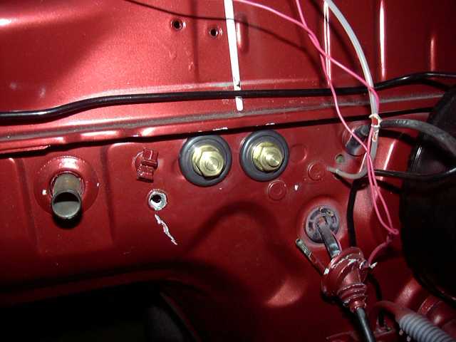
One of the things that really bothers me when people do electrical work is sloppiness. There is absolutely no excuse for bringing cables through unprotected firewall connections. These are battery bulkhead connectors. They provide a pass through that is safe, clean and sanitary. The solid brass bolt in the middle is insulated by a plastic insulator, which screws into the hole and is secured on the other side with a nut. A stud on each end is then provided to make the electrical connection. Not only is this a highly safe and reliable way to pass thick cables through bulkheads, but it also provides a distribution point in the engine bay. From the ground, I can run a thick ground to the engine and the front of the body. From the +12V, a thick wire can go to the starter directly, and then another to the fuse box (and from there, ignition, e-fan, etc.). In this case, the alternator becomes part of the engine harness, which then connects to the battery which is now located inside the car. The disadvantage of these passthroughs is that they are a nightmare to install if the dash is in place. You can see how I had to drill out a stud from the engine side that served to hold the stock dash wiring harness in place. This was done for clearance. The stud has since been welded back into place.
Back inside, here are the finished engine accessories. Intake manifold, water pump and housing, mounts, EGR blockoff, etc.
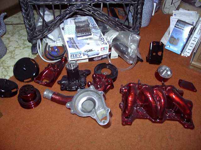
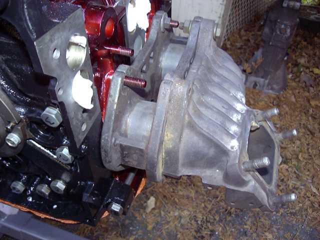
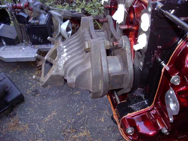
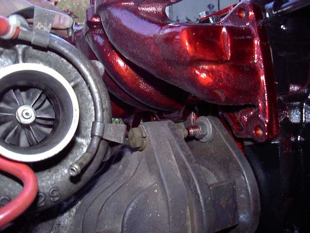
With the engine outside, some mockup was done to make sure everything still fit. These next few pictures provide a great view of the manifold on it's spacer, and how little clearance there actually is between the turbo and lower intake.

Back inside, here are the finished engine accessories. Intake manifold, water pump and housing, mounts, EGR blockoff, etc.
With the engine outside, some mockup was done to make sure everything still fit. These next few pictures provide a great view of the manifold on it's spacer, and how little clearance there actually is between the turbo and lower intake.
Thread Starter
Joined: Feb 2001
Posts: 29,798
Likes: 128
From: London, Ontario, Canada
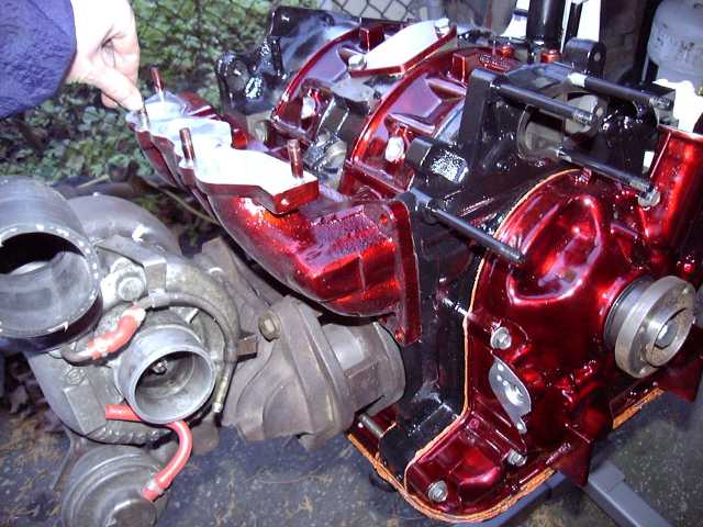
Some great shots of the turbo and lower intake.
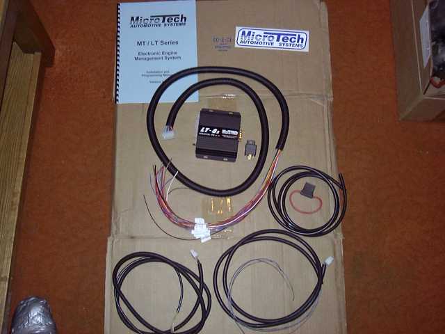
About this time, the Microtech LT-8s arrived in the mail. Shown in the picture is the wiring harness, ECU, vacuum line, relay, instructions and of course the ever important sticker.
Time for a little more wastegate porting. Some of you might recognize these pictures.
Here are the stones I used.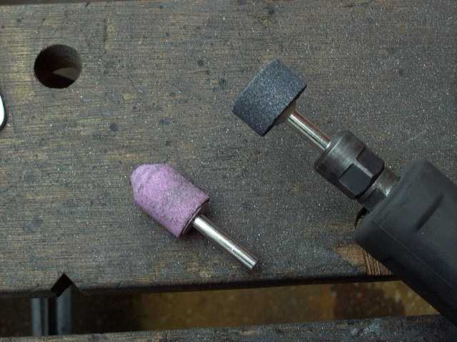
Trending Topics
Thread Starter
Joined: Feb 2001
Posts: 29,798
Likes: 128
From: London, Ontario, Canada
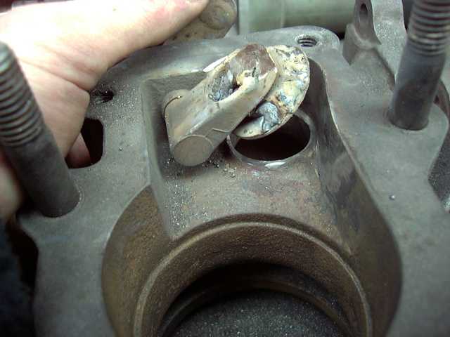
Widening the orifice...
Here's a good shot of the new wastegate passage. It's about twice as large as stock.
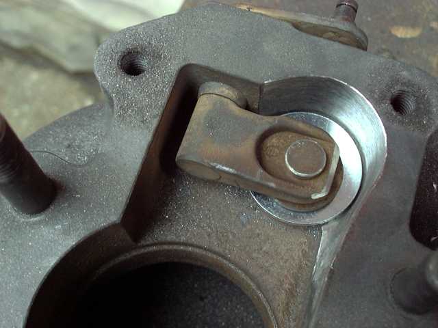
Test fitting the new flapper door.
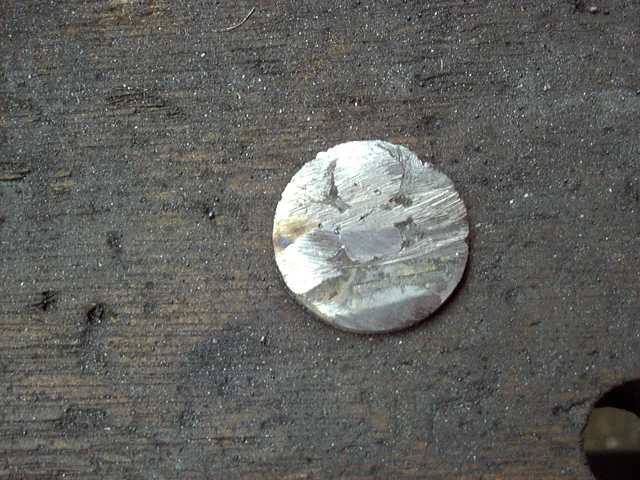
Here's the new flapper door. Two flat washers were simply welded together. The welds were then ground down, and the two washers became as one.
Here's a good shot of the new wastegate passage. It's about twice as large as stock.
Test fitting the new flapper door.
Here's the new flapper door. Two flat washers were simply welded together. The welds were then ground down, and the two washers became as one.
Thread Starter
Joined: Feb 2001
Posts: 29,798
Likes: 128
From: London, Ontario, Canada
Some shots of the new flapper welded in place.
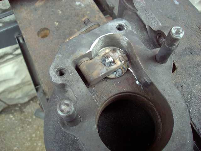
While I'm at it, I figured I would finish porting the exhaust runners. These are not massively ported, since if you make the center divider too thin, it will easily crack (more then it already has).
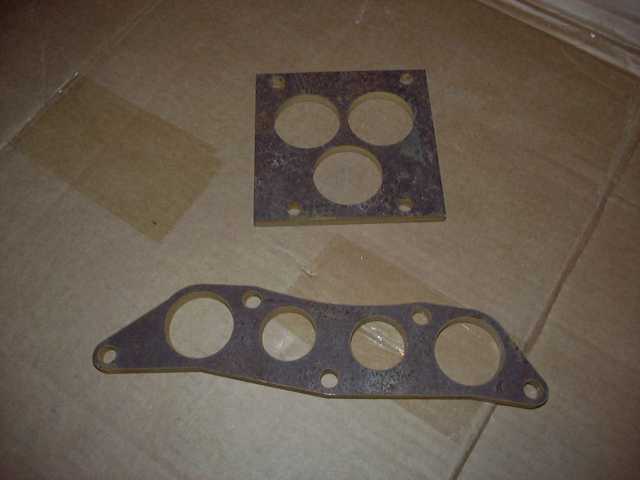
Since I am making a new upper intake for this engine, I needed some flanges cut. I decided to have them done by a machine shop to save some time. So all that was necessary was to design the flange in CAD, and send it to the shop. They cut it out of 8MM steel with a water jet machine. I had a bunch done, so I can experiment with different intakes.
While I'm at it, I figured I would finish porting the exhaust runners. These are not massively ported, since if you make the center divider too thin, it will easily crack (more then it already has).
Since I am making a new upper intake for this engine, I needed some flanges cut. I decided to have them done by a machine shop to save some time. So all that was necessary was to design the flange in CAD, and send it to the shop. They cut it out of 8MM steel with a water jet machine. I had a bunch done, so I can experiment with different intakes.
Thread Starter
Joined: Feb 2001
Posts: 29,798
Likes: 128
From: London, Ontario, Canada
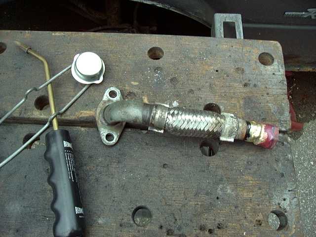
More work on that damn oil pan. I've never been happy with my original turbo drain solution (3/8" 90 degree plumbing elbow). There's nothing fundamentally wrong with it, but there are more elegant ways of accomplishing the task. So I decided to remove the oil drain, and weld on a straight 1/2" NPT pipe union. This would provide a perfect location, that was not in the way of the engine mount like the old drain.
Sometimes, the best laid plans of mice and men just don't work out. I purchased a fancy billet aluminum T4 style oil drain flange from ATP Turbo with the intention of going all braided stainless/AN from the turbo to the pan. Unfortunately, it didn't fit. The flange met up with the holes correctly, but the stock turbo simply doesn't provide enough space between the center section and exhaust flange for any kind of fancy fitting. So I am stuck with the stock drain until I upgrade the turbo. Knowing this, I still wanted the setup to be as reliable and leak proof as possible (I had multiple failures with my old rubber hose). Once again hitting the plumbing isle at Home Depot, I found a 1/2" NPT copper sweat threaded fitting. This was brazed into the cut-off end of the stock drain tube.
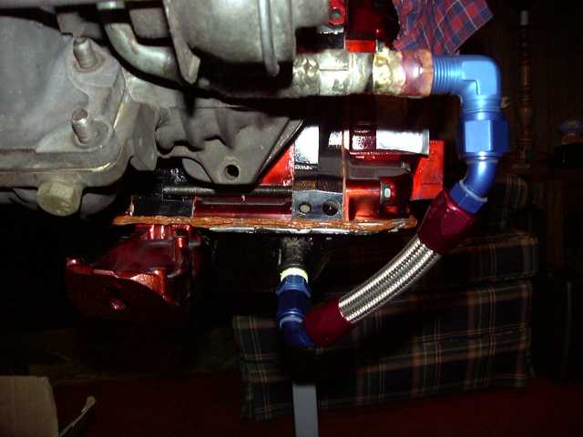
From the brazed fitting, a 1/2" NPT to -10 AN 90 degree fitting was used, and the rest was plumbed in -10 AN and braided stainless. This will never leak. When I upgrade the turbo, the line will be remade to match the new (much more spacious) center section.
Finally, here are the flanges back from the machine shop. The water jet did an excellent job. I also had some throttle body flanges cut for the stock throttle body, even though I won't be using it.
So there you have it. This pretty much brings us up to this weekend. If the weather holds out, the final assembly of the engine (turbo, manifolds, water pump, MOP, flywheel, clutch, etc.) will take place and it will actually be installed in the car. This is a huge milestone, since it means that now I have the location of everything, so fabrication of the upper intake can start, as well as all the wiring, plumbing, etc. I expect things to progress quickly in the engine bay at this point. Now, I can turn my thinking powers to the interior. The seats are heading out to upholstery, and I'm going to tackle the headliner myself. Soon, new carpets will be ordered...
I've never been happy with my original turbo drain solution (3/8" 90 degree plumbing elbow). There's nothing fundamentally wrong with it, but there are more elegant ways of accomplishing the task. So I decided to remove the oil drain, and weld on a straight 1/2" NPT pipe union. This would provide a perfect location, that was not in the way of the engine mount like the old drain.Sometimes, the best laid plans of mice and men just don't work out. I purchased a fancy billet aluminum T4 style oil drain flange from ATP Turbo with the intention of going all braided stainless/AN from the turbo to the pan. Unfortunately, it didn't fit. The flange met up with the holes correctly, but the stock turbo simply doesn't provide enough space between the center section and exhaust flange for any kind of fancy fitting. So I am stuck with the stock drain until I upgrade the turbo. Knowing this, I still wanted the setup to be as reliable and leak proof as possible (I had multiple failures with my old rubber hose). Once again hitting the plumbing isle at Home Depot, I found a 1/2" NPT copper sweat threaded fitting. This was brazed into the cut-off end of the stock drain tube.
From the brazed fitting, a 1/2" NPT to -10 AN 90 degree fitting was used, and the rest was plumbed in -10 AN and braided stainless. This will never leak. When I upgrade the turbo, the line will be remade to match the new (much more spacious) center section.
Finally, here are the flanges back from the machine shop. The water jet did an excellent job. I also had some throttle body flanges cut for the stock throttle body, even though I won't be using it.
So there you have it. This pretty much brings us up to this weekend. If the weather holds out, the final assembly of the engine (turbo, manifolds, water pump, MOP, flywheel, clutch, etc.) will take place and it will actually be installed in the car. This is a huge milestone, since it means that now I have the location of everything, so fabrication of the upper intake can start, as well as all the wiring, plumbing, etc. I expect things to progress quickly in the engine bay at this point. Now, I can turn my thinking powers to the interior. The seats are heading out to upholstery, and I'm going to tackle the headliner myself. Soon, new carpets will be ordered...
Joined: Dec 2001
Posts: 10,630
Likes: 3
From: NY, MA, MI, OR, TX, and now LA or AZ!
You really don't like that front cover do you? Just seems like it would've been the easiest spot to run to now that you had everything apart and could easily drill/tap it.
For some reason I thoughth you were going with a larger turbo from the start. Are you worried about choking that stocker with the half bridge? Also, it looks like you could get away with a lot smaller spacer now that the ACV/etc is cut out, have you tried test fiting it without the spacer and seeing how much more clearance that gave you?
Oh, and that red is damn creepy!
Just seems like it would've been the easiest spot to run to now that you had everything apart and could easily drill/tap it.For some reason I thoughth you were going with a larger turbo from the start. Are you worried about choking that stocker with the half bridge? Also, it looks like you could get away with a lot smaller spacer now that the ACV/etc is cut out, have you tried test fiting it without the spacer and seeing how much more clearance that gave you?
Oh, and that red is damn creepy!
Carter 2.0
Joined: Jun 2004
Posts: 6,262
Likes: 7
From: Irvine Ca.
Everything you do is soooo nice but,
yea, here it comes.........
You need a TIG welder. It looks like your using a MIG. Effective but crude. A TIG with a small beed would look really nice.
Not being an ***, just making a suggestion, like I said you are doing ten times better job than I could.
One more observation, Do you think that the feed through bolts have enough insulation against electrostatic discharge?? I am not familiar with how other feedthroughs are for other applications, is this an industry norm? Just asking ahead of time. I'd hate to see you put it all back together and then have an electrical problem that you couldn't seem to find simply becuase there is a ton of **** in the way. 12V DC is nothing to sneeze at. A simple Hipot test could determine at what voltage you would see a failure. You would have to replace the Rubber at what not after you found the voltage faliure.
Will that piece that is cracked amount to anything.
Thread Starter
Joined: Feb 2001
Posts: 29,798
Likes: 128
From: London, Ontario, Canada
Originally Posted by SonicRaT
You really don't like that front cover do you? Just seems like it would've been the easiest spot to run to now that you had everything apart and could easily drill/tap it.
Just seems like it would've been the easiest spot to run to now that you had everything apart and could easily drill/tap it.
For some reason I thoughth you were going with a larger turbo from the start. Are you worried about choking that stocker with the half bridge?
So I'm going to run the stocker for the first 1000 KM or so. Also, I already have all the parts fabbed up, so using the stock unit means I can get the car on the road quicker since I don't have to make a new manifold, etc.
Also, it looks like you could get away with a lot smaller spacer now that the ACV/etc is cut out, have you tried test fiting it without the spacer and seeing how much more clearance that gave you?
Oh, and that red is damn creepy!
Originally Posted by jhammons01
You need a TIG welder. It looks like your using a MIG. Effective but crude. A TIG with a small beed would look really nice.
One more observation, Do you think that the feed through bolts have enough insulation against electrostatic discharge?? I am not familiar with how other feedthroughs are for other applications, is this an industry norm? Just asking ahead of time. I'd hate to see you put it all back together and then have an electrical problem that you couldn't seem to find simply becuase there is a ton of **** in the way. 12V DC is nothing to sneeze at. A simple Hipot test could determine at what voltage you would see a failure. You would have to replace the Rubber at what not after you found the voltage faliure.
 The only discharge that could ever take place would be between the terminal and the body of the car. And never could a charge build up in the cables that high since there are so many easier points through which it can reach ground. 12V DC is nothing, trust me.
Will that piece that is cracked amount to anything.
Joined: Dec 2001
Posts: 10,630
Likes: 3
From: NY, MA, MI, OR, TX, and now LA or AZ!
I think he's talking about the turbo divider. I usually don't swap over front covers, I just drill out the spot on the N/A cover since the casting is there, just not the holes. I either drill it out and throw in an AN adapter, or use an NPT adapter and go from there. What turbo you got picked out? I'll be using a GT35R when mine's all finished. (Working on my fuel lines now). That color combo is going to be pretty damn sick to look at!

Thread Starter
Joined: Feb 2001
Posts: 29,798
Likes: 128
From: London, Ontario, Canada
Originally Posted by SonicRaT
I think he's talking about the turbo divider.
I usually don't swap over front covers, I just drill out the spot on the N/A cover since the casting is there, just not the holes. I either drill it out and throw in an AN adapter, or use an NPT adapter and go from there.
What turbo you got picked out? I'll be using a GT35R when mine's all finished.
Sweet turbo...dual ball bearing... 
Originally Posted by 91mazdarx7
you did alot your pictures helped me learn more about how to port my wastegate what color is your intake manifolds? are they powder coated? also your doing a great job on the car
Joined: Dec 2001
Posts: 10,630
Likes: 3
From: NY, MA, MI, OR, TX, and now LA or AZ!
Haha, i got the turbo in trade for a car I originally bought for $400! I'm probably going to sell it and get the A-spec T4 version instead though, makes picking a manifold much easier. So far I've got everything done except fuel pump & lines and the exhaust manifold, can't wait to see what that thing does! You're using the same? Seems to be an increasingly popular turbo (hIGGI's car got me hooked on the idea!)
Edit: and I guess it is easier to weld things if you have a welder... Explains why I'm always thinking 'where can I drill now...'
Edit: and I guess it is easier to weld things if you have a welder... Explains why I'm always thinking 'where can I drill now...'
Last edited by SonicRaT; May 26, 2005 at 01:53 PM.
Nice setup.
I do have one Q though.
Your turbo oil drain looks like it dips down and then up at the oil pan. May just be the pic angle though.
I'd think you'd get some good pooling and eventual blowthrough in the turbo.
I do have one Q though.
Your turbo oil drain looks like it dips down and then up at the oil pan. May just be the pic angle though.
I'd think you'd get some good pooling and eventual blowthrough in the turbo.

Thread Starter
Joined: Feb 2001
Posts: 29,798
Likes: 128
From: London, Ontario, Canada
Originally Posted by Digi7ech
Your turbo oil drain looks like it dips down and then up at the oil pan. May just be the pic angle though.
I'd think you'd get some good pooling and eventual blowthrough in the turbo.
I'd think you'd get some good pooling and eventual blowthrough in the turbo.
I wish I was driving!
Joined: Dec 2001
Posts: 5,241
Likes: 84
From: BC, Canada
heh... I was about to ask if that was flux-cored wire... you using a gasless unit, or just run out of shielding? 
No weld-through primer on the sheet metal?
The Sycro 180 is a pretty nice piece of equipment. If you pick one up, you will be very happy with it... its very easy to use as far as TIG's go, and produces decent welds in aluminum. I looked into purchasing one, but ended up stepping up to the syncro 350LX.

Rotary Enthusiast
Joined: Oct 2002
Posts: 1,165
Likes: 0
From: California, Bay Area
If your interested Aaron my NA motor with very similar porting to yours has been up and running for quite some time now. I think you like how it pulls whne its together. I kept my 6-port sleaves functonal tho.