
Oil Pressure Switch Autopsy

Oil Pressure Switch Autopsy
Watch out, we're gonna get all CSI up in here.
For quite a while now I've been running dual oil pressure gauges, measuring the stocker against a VDO.
The stocker is quite accurate, albeit very heavily dampened.
Anyway, I'm now using the VDO (integrated into the gauge cluster) exclusively and was curious about possible differences due to sensor location.
The VDO sending unit has been mounted in a sandwich plate at the oil filter pedestal and I wanted to move it to the stock location.
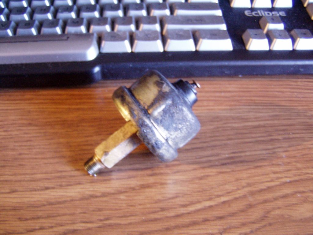
The stock sending unit has two defining features- the thread is odd (not quite 1/8 pipe) and the mounting stud is very long (so it clears the water temp sensor located nearby).
Looks like so:
I cut the mount off, drilled and tapped it for the VDO and got this:

It fits fine and does not leak.
Initial impressions are that the gauge is much less active in this location...not sure if this is true or if it is, why.
Since I'd already killed the stock unit, I decided to cut it open and see what was in there.
Man, nothing like I'd imagined.
In fact, I can't see how it works at all.
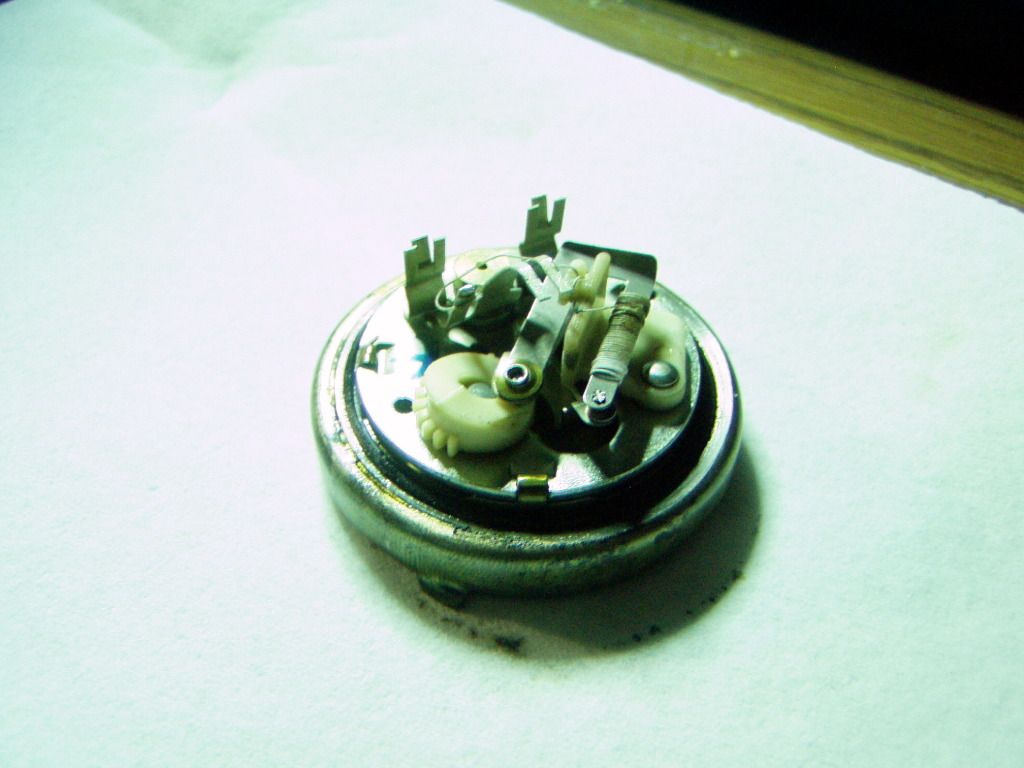
The bottom of the housing- where the oil makes contact- is a solid brass disk, there is no movement or play.
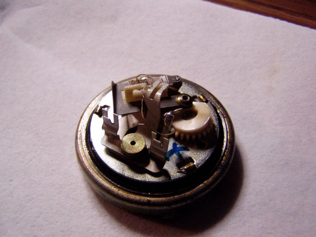
The mechanism shown has no apparent connection to this disk, or any other (potentially) moving part at all.
The white nylon piece with the partial ring of teeth, does not move- it looks like a shaft w/pinion could be set in the hole next to it and used to rotate the part.
This would have to be done during assembly and is probably some sort of sensitivity/limiting adjustment (the part is stepped and places more tension on the contact arm above)...but once set, it ain't moving again.
I have absolutely no clue how this thing works but it was interesting to see it's guts.
For quite a while now I've been running dual oil pressure gauges, measuring the stocker against a VDO.
The stocker is quite accurate, albeit very heavily dampened.
Anyway, I'm now using the VDO (integrated into the gauge cluster) exclusively and was curious about possible differences due to sensor location.
The VDO sending unit has been mounted in a sandwich plate at the oil filter pedestal and I wanted to move it to the stock location.
The stock sending unit has two defining features- the thread is odd (not quite 1/8 pipe) and the mounting stud is very long (so it clears the water temp sensor located nearby).
Looks like so:
I cut the mount off, drilled and tapped it for the VDO and got this:
It fits fine and does not leak.
Initial impressions are that the gauge is much less active in this location...not sure if this is true or if it is, why.
Since I'd already killed the stock unit, I decided to cut it open and see what was in there.
Man, nothing like I'd imagined.
In fact, I can't see how it works at all.
The bottom of the housing- where the oil makes contact- is a solid brass disk, there is no movement or play.
The mechanism shown has no apparent connection to this disk, or any other (potentially) moving part at all.
The white nylon piece with the partial ring of teeth, does not move- it looks like a shaft w/pinion could be set in the hole next to it and used to rotate the part.
This would have to be done during assembly and is probably some sort of sensitivity/limiting adjustment (the part is stepped and places more tension on the contact arm above)...but once set, it ain't moving again.
I have absolutely no clue how this thing works but it was interesting to see it's guts.
What a bizarre little piece of electronics. Paging Hailers or Aaron...
The wire wrapped around the piece on the top (2nd pic) looks a little corroded, but then again I've never trusted the readings I've gotten from any of the senders I've had on either of my cars.
The wire wrapped around the piece on the top (2nd pic) looks a little corroded, but then again I've never trusted the readings I've gotten from any of the senders I've had on either of my cars.


from the pics, looks like they implemented a varistor using the mechanics to sense the pressure, the the coil of wire acts similar to a basic radio receiver.
Assuming I'm right, the mechanics should cause a wire to move over the coiled wire. By varying the position at where the coiled wire meets the movable wire, the resistance of the circuit changes. The gauge acts as a voltmeter, measuring the voltage change due to the resistance change and thus displays a pressure on the face.
Assuming I'm right, the mechanics should cause a wire to move over the coiled wire. By varying the position at where the coiled wire meets the movable wire, the resistance of the circuit changes. The gauge acts as a voltmeter, measuring the voltage change due to the resistance change and thus displays a pressure on the face.
easy, the pressure pushes the cam to turn the gear which pulls on the potentiometer arm to change the resistance value. at least that is how it appears to work to me. if you want to verify, apply some air pressure to the port and watch. i'm assuming under the bell is a diaphragm which is what modifies the gear angle in one way or another. the gear has to move somehow, i think you just can't see how from the topside.
yes it does look very strange and nothing like what i would expect.
i can also envision now why the FD units get sticky.
yes it does look very strange and nothing like what i would expect.
i can also envision now why the FD units get sticky.
Last edited by RotaryEvolution; Dec 19, 2011 at 12:23 PM.
The gear is not connected to anything- and can't be moved by hand at all, nor is there any sort of diaphragm.
Because I've machined it to pieces, I can't blow air into the open end of the port but as I said before, there isn't anything that moves that I can see nor any sort of flexible part for the oil pressure to act on.
If the solid brass plate that blocks the oil does move, it's a very tiny, basically undetectable, amount.
my thought is the gear is driven from the shaft in it's center from the underside. the 3 clamps around the outside edge, you can't disassemble it further to see what is underneath?
Trending Topics
I have taken it further, the "gear/cam" connects to nothing below the plate, nor is there anything that might engage the gear teeth.
There is a lever arm that's mounted on the bottom of he plate you see with a tit that looks like it might have rested on the solid "diaphragm" (no marks on the plate/diaphragm that would indicate much movement though).
This flexible arm creates half of a points type contact- the top half is the arm with the wire wrapped around it.
The two contact surfaces did not touch prior to when I first opened this up, indeed, the gap was so large I don't think they are supposed to ever make contact.
Maybe the current is supposed to jump the air gap like a spark plug?
That would be weird.
If that were so, it'd confirm my initial idea for the toothed cam piece...it's an adjustment to precisely set the air gap between the contacts. Once set, it never moves again.
And, if all this is so, that might explain why the sensor degrades over time...as the "points" burn, the air gap increases and the amount of resistance changes.
There, I just solved all our problems.
Unless I'm wrong.
nah, there's no current. it's a basic resistance sensor circuit. i don't know without opening one myself to see if i could figure it out.
i have a better idea, take a hammer to it and see what it looks like "further disassembled".
lol
i have a better idea, take a hammer to it and see what it looks like "further disassembled".
lol


Thread
Thread Starter
Forum
Replies
Last Post