
No Turn&Harzard aswell as no Door&Dome lights

Thread Starter
Senior Member
Joined: May 2008
Posts: 437
Likes: 0
From: Norway
No Turn&Harzard aswell as no Door&Dome lights
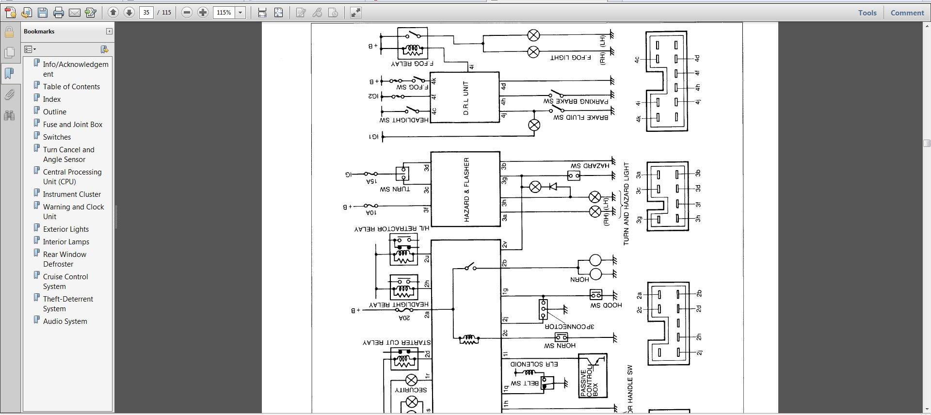
Suddenly 2 weeks ago i notice i have neither blinkers or Hazardlights, or any door & Dome light...I started by checking the fusebox inside the coup� and no fuses were blown there, in other words all ok in the fusebox. Then i checked the diagrams of the blinkers and it seems to me like the blinkers & hazard signals go through a wire and switch into the CPU located just beside the fusebox inside the car, is that correct?
I am missing 2 switches here, ive marked the ones i have and the ones i dont have in the picture below...i also noticed that the lower big green switch on my fusebox inside the car had been pulled out but i havent been down there to do anything but change fuses and never touched the wires except im suspecting something got pulled while i was laying in new wires for my stereo. And the switch that is supposed to go into the bottom slot marked with an X is NOWHERE to be found.....And the manual and the actual switches and pins dont match AT ALL...... :S
It doesnt really make sense with the diagrams or connections either...i am absolutely fuckwadded to as what i can do to find the problem, any suggestions? I had ALOT more to list or write up here but i dont wanna confuse anyone any further in this first post and see what kinda suggestions i get. Thanks everyone
Thread Starter
Senior Member
Joined: May 2008
Posts: 437
Likes: 0
From: Norway
Suddenly 2 weeks ago i notice i have neither blinkers or Hazardlights, or any door & Dome light...I started by checking the fusebox inside the coup� and no fuses were blown there, in other words all ok in the fusebox. Then i checked the diagrams of the blinkers and it seems to me like the blinkers & hazard signals go through a wire and switch into the CPU located just beside the fusebox inside the car, is that correct?
I am missing 2 switches here, ive marked the ones i have and the ones i dont have in the picture below...i also noticed that the lower big green switch on my fusebox inside the car had been pulled out but i havent been down there to do anything but change fuses and never touched the wires except im suspecting something got pulled while i was laying in new wires for my stereo. And the switch that is supposed to go into the bottom slot marked with an X is NOWHERE to be found.....And the manual and the actual switches and pins dont match AT ALL...... :S
It doesnt really make sense with the diagrams or connections either...i am absolutely fuckwadded to as what i can do to find the problem, any suggestions? I had ALOT more to list or write up here but i dont wanna confuse anyone any further in this first post and see what kinda suggestions i get. Thanks everyone
I am missing 2 switches here, ive marked the ones i have and the ones i dont have in the picture below...i also noticed that the lower big green switch on my fusebox inside the car had been pulled out but i havent been down there to do anything but change fuses and never touched the wires except im suspecting something got pulled while i was laying in new wires for my stereo. And the switch that is supposed to go into the bottom slot marked with an X is NOWHERE to be found.....And the manual and the actual switches and pins dont match AT ALL...... :S
It doesnt really make sense with the diagrams or connections either...i am absolutely fuckwadded to as what i can do to find the problem, any suggestions? I had ALOT more to list or write up here but i dont wanna confuse anyone any further in this first post and see what kinda suggestions i get. Thanks everyone


Your CPU should have a 7 wire plug at the bottom which has a Black/Blue wire and this wire should have constant voltage (no key necessary). This plug can be removed from the CPU to test for voltage if it is to cramp to test it while plugged in. If this particular wire does indeed have voltage on it then the 10 amp Hazard fuse is good. If the wire does not have voltage then either the Hazard fuse is bad or the connection is bad or the 60 amp BTN fuse in the Engine bay fuse box is bad. So check for voltage on the Black/Blue wire and see what you get.
Thread Starter
Senior Member
Joined: May 2008
Posts: 437
Likes: 0
From: Norway
Your CPU should have a 7 wire plug at the bottom which has a Black/Blue wire and this wire should have constant voltage (no key necessary). This plug can be removed from the CPU to test for voltage if it is to cramp to test it while plugged in. If this particular wire does indeed have voltage on it then the 10 amp Hazard fuse is good. If the wire does not have voltage then either the Hazard fuse is bad or the connection is bad or the 60 amp BTN fuse in the Engine bay fuse box is bad. So check for voltage on the Black/Blue wire and see what you get.
The wire plug in question is the white one on the first (far left) picture below yeah?
Gonna run down to the garage and have a go for it
Thread Starter
Senior Member
Joined: May 2008
Posts: 437
Likes: 0
From: Norway
As im not a very good handler of electrics i decided to test with an Ohm modus instead of voltage, if i still need to do a voltage test let me know cause then i can have a bud come over tomorrow and help me out, the test with the ohm meter showed no errors in the 7 pin contact, the "signal" pins made my meter beep thou, whatever that means haha (sorry its borrowed so im not familiar with it)
You need to check the voltage. For some reason your wire colors at the 7 wire plug differs slightly from the FSM wiring diagram. The FSM indicates you should have a solid Black wire, a Light Green wire, and four Green striped wires which it appears your plug have, but you don't seem to have the Black/Blue wire but a Red wire instead for some reason. So, you need to check for voltage on the Red wire w/no key in the ignition and this will tell where to go from there.
To check for voltage is rather simple as the meter is first set to "DC voltage" and then the Red meter terminal is placed on the wire that should have voltage and the other meter lead, which happens to be Black, on a suitable ground and the meter will give you the voltage level.
To check for voltage is rather simple as the meter is first set to "DC voltage" and then the Red meter terminal is placed on the wire that should have voltage and the other meter lead, which happens to be Black, on a suitable ground and the meter will give you the voltage level.
Thread Starter
Senior Member
Joined: May 2008
Posts: 437
Likes: 0
From: Norway
So ive checked the voltage on the connection in the CPU and it got...well..something...im using mV mode which im guessing is milliVolts and it keeps running up to about 400.0 mV then starting the cycle from 0 and up to 400 again and keeps on doing this...btw the Domelights and courtesy lights are back, just turn and hazards missing now
Trending Topics
Thread Starter
Senior Member
Joined: May 2008
Posts: 437
Likes: 0
From: Norway

It would be illustrated as DCV with an equal sign above the V.

If you must use milli volts then use millivolts. Use the Black wire in the 7 wire plug as your ground for the Black meter lead and the Red meter lead to the Red wire w/key to on and it should read 12 volts or in your case 1200 millivolts.

If you must use milli volts then use millivolts. Use the Black wire in the 7 wire plug as your ground for the Black meter lead and the Red meter lead to the Red wire w/key to on and it should read 12 volts or in your case 1200 millivolts.
Thread Starter
Senior Member
Joined: May 2008
Posts: 437
Likes: 0
From: Norway

Thread Starter
Senior Member
Joined: May 2008
Posts: 437
Likes: 0
From: Norway
Yeah...no ive kinda had it with this car. Multimeter gives me a diff f*cking measure every time and the car itself basically seems possessed by the devil. Im so distraught atm after over a month of trying to fix this that im about too break out and cry like a little frikkin girl...Im just trying too find out how i can punish the car...and that itself (wanting to punish an OBJECT) should say something
Thread Starter
Senior Member
Joined: May 2008
Posts: 437
Likes: 0
From: Norway
After a weeks break ive gotten back to it and i think i found a few "broken" wires in the 7 plug switch, what i dont get is that this 7 plug connector cannot be found in the manual :S its drawn as a 12 space switch there. Anyone have a corrected diagram or just know and can identify them all?

Thread Starter
Senior Member
Joined: May 2008
Posts: 437
Likes: 0
From: Norway
Well urm...the beepie(<-LOL) thingy on my multimeter doesnt go off when i measure those and what i THINK is the ground, i found the manual via ur pics webadress and im gonna have a read over today and tomorrow and ill be up to speed on whats what
Your're getting the beeping sound because you're likely measuring volts in milliamps as opposed to volts. When measuring for volts there is no beeping sound to be heard. You need to take the manufacturer and model number of your multimeters and do a search on each to show you which setting you need. Out of the two you have you should be able to get one dialed into the proper setting. DC mA is for measuring milliamps as the "A" stands for amps and not volts.
Thread Starter
Senior Member
Joined: May 2008
Posts: 437
Likes: 0
From: Norway
Nono that was a resistance measure i did with the beeping. i thought maybe it should beap on all wires if they didnt have a broken curcuit...daargh im a elec-noob for real sorry haha . Will measure voltage also thou, had too work on some other small issues with the wiring and will get at the blinkers tomorrow
When you do a continuity test you place one meter lead on one end of the wire and the other meter lead on the other end and if it beeps if the wire is continous or unbroken but this test has its limits.
The B/L wire should have constant voltage, no key necessary, but in your pic of the 7 wire plug it appears you do not have this specific color wire and it looks like you have a Red wire in its place.
Secondly, the Green/Red wire should have voltage w/key to on and the turn signal lever set to left hand turn. The Green/Yellow wire should have voltage w/key to on and the lever set to right hand turn.
Thread Starter
Senior Member
Joined: May 2008
Posts: 437
Likes: 0
From: Norway
Pulled a new wire on the red/Battery cable and out to the battery Baddabing baddabom its fixed  Thank you so much for your help buddy, im glad it took as long as it did too solve the issue because i basically learned the ABC`S of this cars electrics
Thank you so much for your help buddy, im glad it took as long as it did too solve the issue because i basically learned the ABC`S of this cars electrics