
New Intake Design

Thread Starter
Rotary Rocket
Joined: Aug 2006
Posts: 395
Likes: 1
From: St.Louis
New Intake Design
Here's a manifold I came up with over the weekend. I'm actually supposed to be working on the auxiliary ports, but the barrel throttles were fun to draw. The proportions of the engine are messed up, but it gives you some idea of what it should look like.
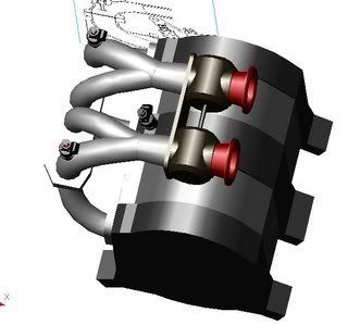

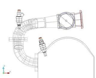
what do you guys think?
what do you guys think?

Full Member
Joined: Sep 2006
Posts: 95
Likes: 0
From: US
ITB's? Interesting. I think I've seen someone that sells a TB velocity stack combo. Back on topic. Nice drawing/ idea. I wonder if anyone will ever design a variable length intake runner system like the one used on the 787B.
Rotary Freak
Joined: Jan 2004
Posts: 2,116
Likes: 1
From: Northern California
I plan to run something similar on my FC. I'll be using off-the-shelf parts, though. DCOE upper manifold with a slightly modified stock lower intake manifold, and I'll utilize a pair of TWM 48mm throttle bodies. I'll let you guys know how it works out in about 4 or 5 months, hopefully I can break 200rwhp N/A with a mild streetport.
http://www.rotaryshack.com/Products/...sp?intView=100 i bet if you ask these guys they will probably make it for you.
Thread Starter
Rotary Rocket
Joined: Aug 2006
Posts: 395
Likes: 1
From: St.Louis
thanks for the feed back guys. actually i have a guy locally making it for me for free. no telling when ill get it started tho. i have to get him the materials to machine and build. as for the ecu, i have a friend whose running something similiar and hes actually using the stock ecu. its not exactly efficient but he wasnt left with enough cash to megasquirt it. Ill probably design a penelum(air volumizer) to put around the trumpets. 13turbofc, basically you get a shorter length for the intake to pull air in. if you look at the stock manifold it curves under itself and is rather long. i designed it with 2 separate pipes for each rotor to have its own intake. just seemed logical.
Trending Topics
There is a reason the stock intake manifold is that long, low end torque. Its what makes the car somewhat decent for the street.
With a shorter IM the power band is shifted up. The bad thing about this is that with the stock ECU, you cannot take full advantage of it. Not to mention the heavy S4 rotors and stock ports will limit how high you can rev.
The plenum should be placed after the throttle for maximum driveability at part throttle.
Joined: Feb 2001
Posts: 29,798
Likes: 128
From: London, Ontario, Canada
That's some nice work! But it's not exactly new.  Take a look at the Renesis intake...
You're going to want some kind of air volume after the throttle bodies. It will help tremendously with throttle response.
Take a look at the Renesis intake...You're going to want some kind of air volume after the throttle bodies. It will help tremendously with throttle response.
Thread Starter
Rotary Rocket
Joined: Aug 2006
Posts: 395
Likes: 1
From: St.Louis
thanks alot. i know its not a new design but i was really just wanting to design something with acad(i get bored easily). then i really started to think about it. I forgot to add the air volume but it is in my next design. this one is taking forever but when it is ill post it.

If I might make a suggesting: Throttle the secondary/aux ports together and the primarys together. If you throttle them with each other you wont get any high pressure wave benefit at any point. If you throttle the secondarys and primaries seperately then at least at some point in the mix the high pressure wave from the intake port closing will reach the chamber at the same time that the other intake port is opening, causing the same effect as the VDI.... If you did that I would stack them on top of each other, or stagger vertically so that the runners are the same length to the barrel.
If you are doing this on a turbo its not nearly as important. Otherwise it looks good. You could probably source TB's from an Honda RC51 or Ducati sport bike.
BC
If you are doing this on a turbo its not nearly as important. Otherwise it looks good. You could probably source TB's from an Honda RC51 or Ducati sport bike.
BC

Passing life by
Joined: Feb 2005
Posts: 4,028
Likes: 2
From: Scotland, USA
Originally Posted by Cpt.Zanzibar
Here's a manifold I came up with over the weekend. I'm actually supposed to be working on the auxiliary ports, but the barrel throttles were fun to draw. The proportions of the engine are messed up, but it gives you some idea of what it should look like.
what do you guys think?
what do you guys think?
This is the most important aspect of the motor. Unfortunately the hardest to tune. Remember as the RPMS rise the pressure waves change and the reverb into the intake is also changed. Account the amount of volume needed for the trailing bounce of the reverb to be picked up on the scavenging timing and volume of the ports. Your high point of the velocity pulse will carry a high pressure zone and the trailing will carry a low pressure zone. When you get the reverb these will colloid and stall your intake. This is where runner bounce comes from, more prominent on NA engines. Things as bends and actuators are used to counter it.
Originally Posted by C. Ludwig
Everything except the barrel throttles is easily available from RB and TWM. The plenum takes some work. Another Ludwig Motorsports product.

Lives on the Forum
Joined: Sep 2003
Posts: 5,707
Likes: 6
From: BC, Canada
You can even get roller throttles comercially. Here's a pic of some webber flanged ones.
http://www.flyinmiata.com/projects/c...flip.php?x=674
Also on this page you can see another option for the intake manifold.
http://www.yawpower.com/dec2004.html
http://www.flyinmiata.com/projects/c...flip.php?x=674
Also on this page you can see another option for the intake manifold.
http://www.yawpower.com/dec2004.html
Lives on the Forum


Joined: Oct 2004
Posts: 5,179
Likes: 171
From: Japanabama
If you're gonna go and make a custom manifold with ITBs, why not just put the secondary injectors on the lower half of the manifold, closer to the ports (basically spraying right into them)? Seems like it would work better...
Respecognize!
Joined: Sep 2004
Posts: 4,106
Likes: 73
From: Anchor Bay, CA
i agree with the statement made before. the primary and secondary ports really shouldnt be on the same TB. Look at any factory EFI manifold for the rotary. the secondary and primary ports are seperated hense the three plate TB design. Helps driveability a ton too.
