New Intake Design
 11-18-06, 03:51 PM
#26
Passing life by
Originally Posted by rogrx7
This is basically what he told me. The guy also has a pretty nicc FC as works at a shop.

 11-18-06, 04:07 PM
#27
The mystery of the prize.
asymmetry isnt such a big deal, if there is an effect on the efficiency of a specific portion any reasonable standalone permits tuning per-injector.
even my r1's factory computer has individual injector trim adjustment available through the gauge cluster.
Just because an intake appears symmetrical or ideal in your mind, injectors are not all equal, manifolds and runners have internal variations, the ports @ the motor vary, everything has variance, ultimately the tune has to compensate for variations everywhere.
11-18-06, 04:34 PM
#28
Passing life by
Yes the tune can compinsate but that would require an EGT on each output and not tuning just per single colector wide band. Not meany people spend that much money and show me one tuner who would like to tune per single EGT and not be able to trust the wide band very much. I think they would all like to have a balanced system to tune from with individual EGT.
11-18-06, 06:13 PM
#29
Lives on the Forum
By your logic then a 4 cylinder engine with a manifold with the TB on one end of the plenum (just like 99% of all I4's out there) will kill a motor. That's just not right. Asymmetry in the plenum won't will a motor, having different runner lenghts is bad though, you're confusing the two.

 11-18-06, 08:01 PM
#36
ENGAGE LUDICROUS SPEED!!
Join Date: Aug 2006
Location: south florida
Posts: 125
Likes: 0
Received 0 Likes
on
0 Posts
Originally Posted by Valkyrie
Why in gods name would someone go to that much trouble to put the power to the wrong wheels?
They should have just made it a midship...
They should have just made it a midship...
Last edited by wankelme!; 11-18-06 at 08:11 PM.
11-18-06, 08:09 PM
#37
Eats, Sleeps, Dreams Rotary
Yeah, IMO FWD drag is for people who would rather prove a point than go fast :p
That setup would probably be badass in a road racing car... but with no turbo I can't imagine it would be all impressive as a drag car... at least, probably no more than 350 HP (even if it's a PP...).
That setup would probably be badass in a road racing car... but with no turbo I can't imagine it would be all impressive as a drag car... at least, probably no more than 350 HP (even if it's a PP...).
11-18-06, 08:49 PM
#38
Passing life by
Originally Posted by rotarygod
Actually that design isn't bad at all. It should flow quite evenly between the runners. It isn't very pretty but that doesn't matter.
Last edited by iceblue; 11-18-06 at 08:56 PM.
11-18-06, 09:13 PM
#39
Lives on the Forum
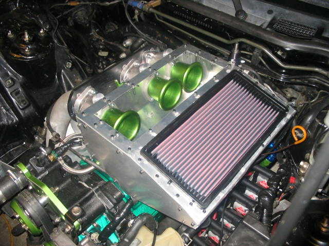
I know from reading about a local guy doing development on an IRTB Miata that having as large of an air box as is physically possible is best, and putting a filter straight on top of the TB's is bad because you get very turbulent air coming out of the filter, whereas in an airbox it should have time to settle down and become laminar.
11-18-06, 10:10 PM
#40
Rotary Apprentice
Join Date: Jan 2005
Location: USA
Posts: 2,181
Likes: 0
Received 0 Likes
on
0 Posts
Originally Posted by Sideways7
One of the best designs I saw was where it had ITB's with a rectangular box around them and the intake hole in the middle of it. That or he had the box open to the top to use the turbo scoop as a CAI, I can't remember.
i love this car!
11-18-06, 10:17 PM
#41
Eats, Sleeps, Dreams Rotary
Um, I don't get why someone would bother fabbing up a plenum for ITBs when they could just put small filters on each of the throttles... it makes sense if it's for a hood scope or a cold-air intake, but otherwise I think filters on the throttles makes more sense (and it's not like you loose the cool induction sound...).
...or if it's for a turbo...which that isn't.
...or if it's for a turbo...which that isn't.
11-18-06, 11:15 PM
#42
Lives on the Forum
I JUST explained that. When just sticking a little filter on top of the TB's you're getting lots of turbulent air into the TB's whereas with a airbox you'll have a much greater chance of having laminar flow and getting more air, and more power. You can also get a COLD air source and aren't stuck with HOT engine compartment air that's been heated by the rad, the oil cooler, the exhaust system and all the other hot things in there. You'll get a few % more power right there from air that's dosens of degrees cooler.
11-18-06, 11:41 PM
#43
Eats, Sleeps, Dreams Rotary
...woops :p
I don't read *every* post you know. But wouldn't that box get just as heatsoaked as the rest of the engine bay? It doesn't really seem oriented in a way that would be useful for sucking air in (unless there's a big hole in the hood).
I don't read *every* post you know. But wouldn't that box get just as heatsoaked as the rest of the engine bay? It doesn't really seem oriented in a way that would be useful for sucking air in (unless there's a big hole in the hood).
11-19-06, 12:59 AM
#44
Rotary Enthusiast
iTrader: (1)

Join Date: Oct 2005
Location: Raleigh, NC
Posts: 1,017
Likes: 0
Received 0 Likes
on
0 Posts
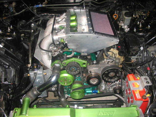
What hasnt been mentioned, and what I forgot to mention, about the setup on the first page is the distance from the TBs to the ports.
The benefit of ITBs comes from increased flow ability, and low throttled volume. The closer you can get the TBs to ports, the less volume of air there is behind the TBs, the less time it takes for throttle inputs to result in action. So short of the increase in flow ability, your setup doesnt help throttle responce very much. I would suggest finding a way to move the throttles closer to the intake ports, and then you also will gain the ability to vary the intake runner length of the Secondary ports in relation to the primary ports without having to figure out a crazy throttle linkage.
BC
11-19-06, 05:49 AM
#45
The mystery of the prize.
Originally Posted by iceblue
Yes the tune can compinsate but that would require an EGT on each output and not tuning just per single colector wide band. Not meany people spend that much money and show me one tuner who would like to tune per single EGT and not be able to trust the wide band very much. I think they would all like to have a balanced system to tune from with individual EGT.
once you normalize by tuning the individual trims the collected exhaust AFR is meaningful.
I have type-k thermocouples in my exhaust runners, it wasnt expensive... especially after you've already spent far more dollars building up a race car, some sensors and data acquisition are just a drop in the bucket.
Just because everything looks identical you cant run on assuming your collected exhaust AFR is a represntation of uniforum conditions, either way you have to put egts in each exhaust runner if you want to tune it right, I mentioned it already, there are manufacturing variances everywhere.
Asymmetry is not a bad design, it's just a different design. Builders will use asymmetry to their advantage to flatten out torque curves rather than having all engines (each rotor/piston is basically a small engine) come 'on cam' at the exact same moment, which often makes the torque curve peaky... For example, some people will vary the uncollected lengths on the exhuast or intake sides to change the shape of the curve, this can have a dramatic effect on drivability in different conditions (dirt vs snow vs gravel vs rain vs dry sticky asphalt vs flat vs hilly etc). Although when you only have two rotors to work with you're fairly limited, but on something like a 4/6/8 cylinder or a 4 rotor you have a good number of ***** to tweak.
In turbo applications people generally just change the turbo to change the shape of the curve, but with NA you have to do more invasive things. Generally with NA uniformly changing the length of runners will shift the curve up or down the rev range, but to change the shape you change valve timing (port on rotary) or tune the lengths differently per rotor/cylinder.
In the photographed intake above I doubt it has much impact on anything, unless the motor flows enough air for that air box to become anemic, if it's volume is too low then I believe you'll start seeing bias towards one rotor near higher rpms... but that doesnt necessarily mean the overall design is poor, it could just need more cubes.
11-19-06, 10:48 AM
#46
Engine, Not Motor
iTrader: (1)
Join Date: Feb 2001
Location: London, Ontario, Canada
Posts: 29,789
Likes: 0
Received 108 Likes
on
91 Posts
Originally Posted by Low Impedance
i agree with the statement made before. the primary and secondary ports really shouldnt be on the same TB. Look at any factory EFI manifold for the rotary. the secondary and primary ports are seperated hense the three plate TB design. Helps driveability a ton too.

Originally Posted by Black91n/a
If going custom with the TB's and manifolds you want to place the injectors as FAR away from the ports as possible, because it leaves more time for better fuel atomisation.
Originally Posted by Low Impedance
that and wont moving the injectors back cause a delay between the time when its injected and the time when its actaully in the combustion chamber?
I'm helping on an engine right now where the secondaries are at least 20" from the intake ports. In my intake, the secondaries are about equal to the stock distance in the NA (the TII injectors mount much higher).
Originally Posted by Sideways7
One of the best designs I saw was where it had ITB's with a rectangular box around them and the intake hole in the middle of it. That or he had the box open to the top to use the turbo scoop as a CAI, I can't remember.
Originally Posted by iceblue
Optimal would be centered. Exactly why the OEM setup is placed in the middle of the dynamic chamber. The radius would flow well but a bad DC. Thu the setup it is on is not running a DC TB it is simply an air channel it matters nothing, I actually thought it was a DC since I had it already in my head as we are on a custom intake thread and not air ducting to the TB. Irrelevant post threw me off. Anyways refer to my first sentence in this post in conjunction to DC. Apology for the confusion.
If you look at a lot of OEM cars, you will find that most of the throttle bodies are at one end of the plenum. Most aftermarket intakes are the same as well. Unless you are working to try and take advantage of the air spring created by the intake pulses plenum it's really not a concern. Doing such a design for the average home mechanic involves basically making a bunch of intakes and dynoing them, which gets old really quickly.
11-19-06, 11:07 AM
#47
Actually that pic posted is the one I was thinking of at the time. I had forgotten it was the NA 20b. doesn't it have a semi-peripheral port or something? Anyway, I swear I saw pics of one that used a box that utilized the TII scoop for a cai, though, so maybe thats the one you're talking about Aaron.
11-19-06, 11:11 AM
#48
Passing life by
Originally Posted by pengarufoo
once you normalize by tuning the individual trims the collected exhaust AFR is meaningful.
I have type-k thermocouples in my exhaust runners, it wasnt expensive... especially after you've already spent far more dollars building up a race car, some sensors and data acquisition are just a drop in the bucket.
Just because everything looks identical you cant run on assuming your collected exhaust AFR is a represntation of uniforum conditions, either way you have to put egts in each exhaust runner if you want to tune it right, I mentioned it already, there are manufacturing variances everywhere.

Originally Posted by pengarufoo
Asymmetry is not a bad design, it's just a different design. Builders will use asymmetry to their advantage to flatten out torque curves rather than having all engines (each rotor/piston is basically a small engine) come 'on cam' at the exact same moment, which often makes the torque curve peaky... For example, some people will vary the uncollected lengths on the exhuast or intake sides to change the shape of the curve, this can have a dramatic effect on drivability in different conditions (dirt vs snow vs gravel vs rain vs dry sticky asphalt vs flat vs hilly etc). Although when you only have two rotors to work with you're fairly limited, but on something like a 4/6/8 cylinder or a 4 rotor you have a good number of ***** to tweak.
Originally Posted by pengarufoo
In turbo applications people generally just change the turbo to change the shape of the curve, but with NA you have to do more invasive things. Generally with NA uniformly changing the length of runners will shift the curve up or down the rev range, but to change the shape you change valve timing (port on rotary) or tune the lengths differently per rotor/cylinder.
Originally Posted by pengarufoo
In the photographed intake above I doubt it has much impact on anything, unless the motor flows enough air for that air box to become anemic, if it's volume is too low then I believe you'll start seeing bias towards one rotor near higher rpms... but that doesnt necessarily mean the overall design is poor, it could just need more cubes.
11-19-06, 11:23 AM
#49
Passing life by
Originally Posted by Aaron Cake
The RX-7s throttle body is centered to match up with the intake runners and keep them equal in length.
Originally Posted by Aaron Cake
Assuming the flow characteristics between rotors are identical, then runner length must be the same between them. However it's not hugely important where the air enters are plenum because the real "spring" of air forms at the mouth of each runner. The plenum always remains at a higher pressure then the runners and thus plenum velocity is not really important (it's a very turbulent area regardless of where the throttle body enters).
Originally Posted by Aaron Cake
If you look at a lot of OEM cars, you will find that most of the throttle bodies are at one end of the plenum. Most aftermarket intakes are the same as well. Unless you are working to try and take advantage of the air spring created by the intake pulses plenum it's really not a concern. Doing such a design for the average home mechanic involves basically making a bunch of intakes and dynoing them, which gets old really quickly.

