
Miata Cluster Swap


Hey Clokker -
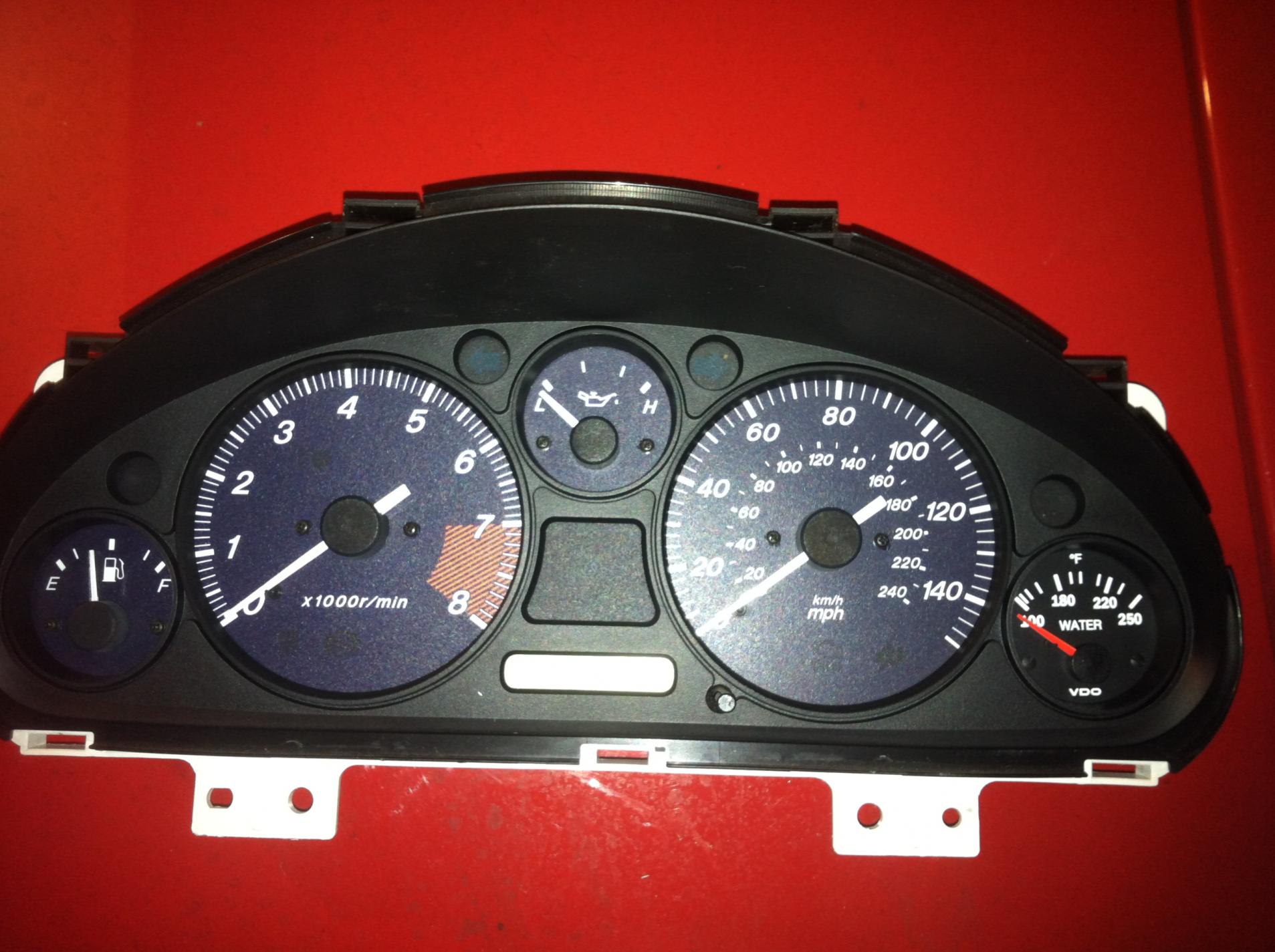
I've been inspired by your work with the miata cluster. I had the same '99 cluster that you got sitting around for my other project car but decided to follow you and do the same transplant. Here's a pic of what I have so far. The VDO gauge I had is a vision series. The spades are not molded into the body rather they have two ears that are slightly crimped to hold it in place. After removing the bezel and glass and unbending the ears on the spades the entire assembly removes easily with a little persuasion. Once the gauge is out of the housing the spades can be removed since they are just bullet connectors plugged into the actual gauge. I then drilled a hole for the screw to poke through the back.
I'll post more pictures later. Unfortunately, this will have to go on hold for now while I try to figure out how to replace the cables in my vert's driver side window regulator. =(

Matter,
Yeah, I discovered all that about the VDOs.
Very nice job you did...is the gauge connected yet?
I'm not sure how to deal with the difference in graphics between the VDO and stock dials.
They're close enough that it may not matter and the advantages of not screwing with the needle and dial are great.
Did you get pigtails with your cluster?
If so, lucky bastard.
If not, what is your plan?
Unfortunately I did not get the pigtails with it. So my plan is to try to solder directly to the circuit paper. I have the board from the back of an s5 cluster that I'm going to try and cut out the pins to make an adapter with.
I'm not concerned that the black of the gauges doesn't match but I haven't decided what to do about the pointer yet. More importantly I need to get an fd vss to mod too.
I'm not concerned that the black of the gauges doesn't match but I haven't decided what to do about the pointer yet. More importantly I need to get an fd vss to mod too.
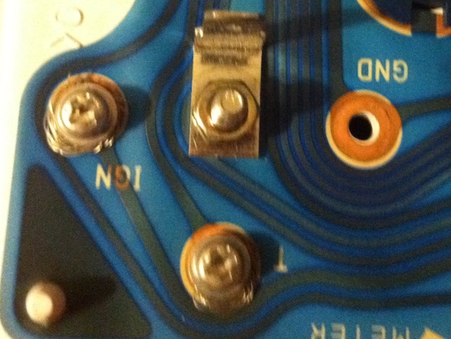
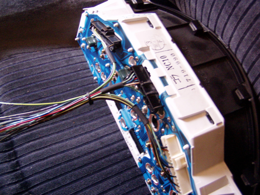
Here's a couple of pics of how I attached the gauge. The screw from the gauge goes right through where the plastic pin was that held the circuit paper in place. I did have to add a spacer on the screw behind the gauge to keep it at the proper height.
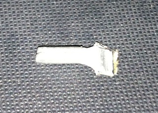
I took the spade connectors and cut them down and soldered an 18awg wire to it about 2.5" long. I then stripped off about .75" of insulation and ran it through the hole. The original screws are just the right size to screw in with the bare wire. You can sort of see in the picture where the wire is wrapped around the screw. I haven't hooked up the ground wire yet but will prolly not use the original ground spade and just use a jumper with eyelets covered in shrink wrap.
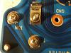
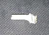
I took the spade connectors and cut them down and soldered an 18awg wire to it about 2.5" long. I then stripped off about .75" of insulation and ran it through the hole. The original screws are just the right size to screw in with the bare wire. You can sort of see in the picture where the wire is wrapped around the screw. I haven't hooked up the ground wire yet but will prolly not use the original ground spade and just use a jumper with eyelets covered in shrink wrap.
Unfortunately I did not get the pigtails with it. So my plan is to try to solder directly to the circuit paper. I have the board from the back of an s5 cluster that I'm going to try and cut out the pins to make an adapter with.
I'm not concerned that the black of the gauges doesn't match but I haven't decided what to do about the pointer yet. More importantly I need to get an fd vss to mod too.
I'm not concerned that the black of the gauges doesn't match but I haven't decided what to do about the pointer yet. More importantly I need to get an fd vss to mod too.
Not going to happen.
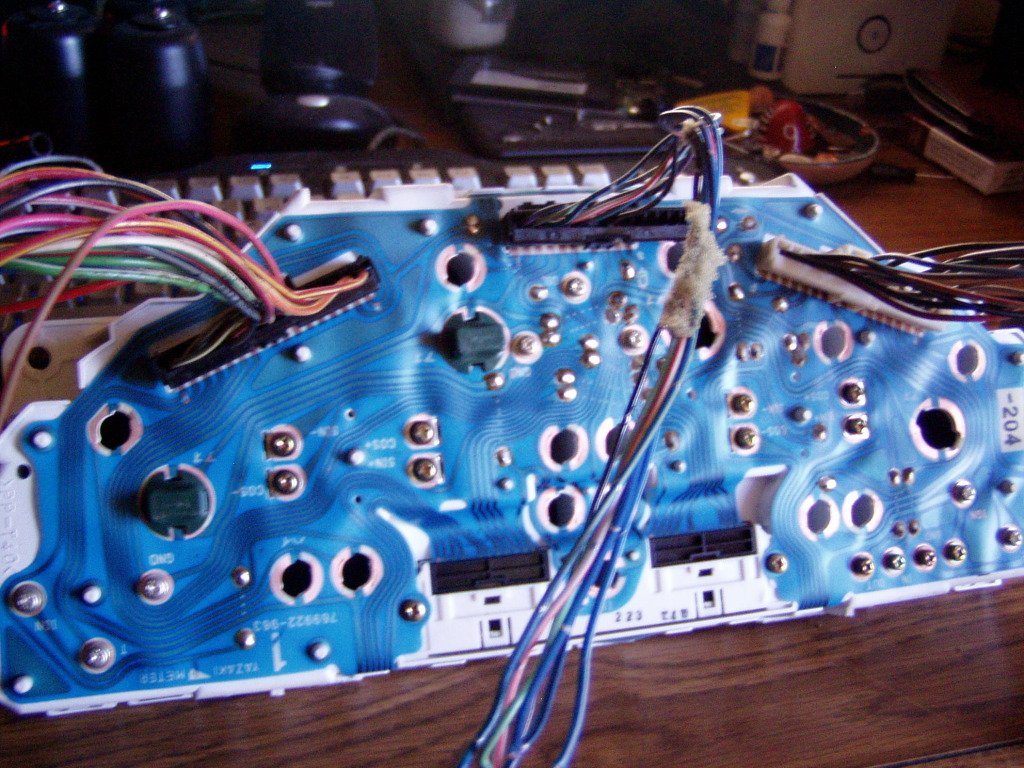
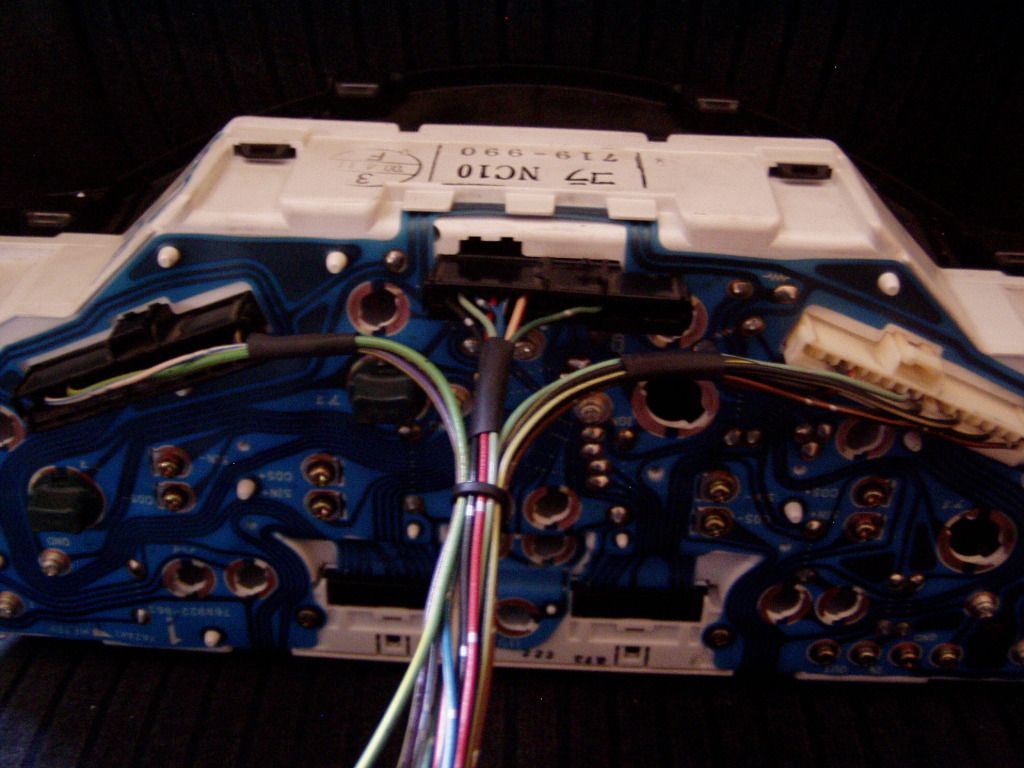
The real connectors are not only keyed on the top, but there is a pattern to the contacts themselves. If you look at the pic above that shows the back of the cluster, you'll see that the contacts are grouped...seven contact strips, then a gap, then six more...etc.
I can match the top key but then the contacts will not line up properly.
Aaarrrgh.
I've searched eBay for Miata dash harnesses and the (generally crappy) pics don't show the connectors for the cluster.
This makes me hope that there is a separate subharness that plugs to the dash harness and then splits into the three gauge connectors...basically like the FC harness works.
If this is so, I wonder how pricey the part is.
Naturally, there isn't a single Miata in my local yard to check my theory on, so more tiresome research is needed.
@GrayMatter:
I can see the attraction of soldering directly to the circuit paper and may well have to do that myself.
I certainly wouldn't bother cutting up the FC "motherboard" just to salvage those awful pin connectors though. I'd just find a suitable connector set ("suitable"= "right number of contacts") from another car and splice that in.
I'm off to the yard this morning in search of just that thing...
Good news, everyone!
After a fruitless search through the junkyard, I was about to give up on finding connectors when I decided to wander over to the Ford section and make a Hail Mary pass through the Mustangs and Taurii.
Much to my surprise, the first car I searched- a 1996 Mustang- yielded the two most difficult connectors, the two big ones on either side of the cluster.
They are a direct fit, everything is absolutely perfect.
If needbe I can fake the center connector by modifying a 626 part...it wouldn't be ideal but would work OK, I think.
This may all be moot (at least for me) as the eBay seller of my cluster has promised to send out some pigtails.
That would be sweet- and way above and beyond his obligation- but I can carry on now either way it works out.
Good.
Right here. sir...
The two outermost connectors are from the '96 Mustang, the center one is a trimmed down 626 part.
OK, now that this hurdle has been cleared, let's see what's next...
The two outermost connectors are from the '96 Mustang, the center one is a trimmed down 626 part.
OK, now that this hurdle has been cleared, let's see what's next...
And a bit further along...
I have depinned all the unused wires from the connectors (quite a few, actually) and changed most of them so the wire colors are correct and match the Miata diagram (almost all of which match the FC as well).
Here is the pinout for the three connectors:
I.
A-to fuel level sender
B-*
C-+12v switched
D-*
E-*
F-+12v
G-*
H-ground
I-High Beam
J-*
K-*
L-*
M-to VSS (yellow)
N-ground
O-*
P-*
II.
A-to coolant sender
B-*
C-*
D-*
E-*
F-*
G-*
H-*
I-*
J-*
K-*
L-*
M-to VSS (green)
N-*
O-MIL
P-*
III.
A-TS left
B-*
C-brake fluid level*
D-*
E-to oil pressure sender
F-+12v
G-illumination
H-ground ?
I-TS right
J- ground
I followed Mazda's nomenclature for the connectors here...in the pic above #I. is the large white connector on the right, #II. is the large black one on the left and #III. is the center. "A" is on the far right of each unit and progresses to the left.
Now I have to graft this to the FC harness connector.
I took a bit of a sidetrip and experimented on the old mechanical Miata speedo dial, looking to remove the green tint.
Here's how our dials are made:
It starts as a clear disk.
The dial side (the side you see) is printed black with all the graphics left clear.
Now on the back, a thin layer of white is applied followed by a thin layer of green.
This gives the effect of white lettering during the day (frontlighting) but green at night (backlighting).
To achieve white light at night, the green layer must be removed...no small feat without messing up the white below.
I was using a very crude rag + acetone technique and it semi-worked.
I was able to mostly remove the green without damaging the white but from the front, the graphics looked streaky and dull.
So, I think I need to change my approach.
Maybe try a less aggressive solvent (GooGone was recommended) and Q-tips instead of a tshirt.
Another semi-bummer...none of the red needles I came up with fit the Miata shafts.
I may be able to ream them (clockmakers have all sorts of seriously small tools...) but unless I can figure out the dial process, there's no reason to fool with 'em.
Addendum to post #85...pin 2K is the tach signal.
The cluster is in and functional.
Well, everything save the speedo...I need to make the subharness running from the VSS up to the cluster housing, that will happen soon.
It's pretty straightforward, the pinout above (with the addition of the tach) is correct, the only hitch- and a minor one at that-is that a source of constant (battery) voltage must must be found.
I assume this keeps the digital display memory persistent when the car is off because the stock cluster doesn't have any such voltage source.
Other than that, it's cake.
Pics to follow.
Here's something I've never done before:
I would like to publicly thank and recommend to the forum an eBay seller called Panic Motorsports, specifically, Steve.
I bought my latest Miata cluster from him, the part/price were fine, shipping, very fast (and free!).
A week or so later, as the difficulty finding connectors became more dire, I sent a Hail Mary email asking if maybe Panic could help me out.
I then went to the junkyard where I found the Mustang connectors and was saved.
When I got home, I found a message from Steve saying yes, he had the harness and had sent it along already...no charge.
Today, two days later (say what you will about the USPS but really, two days!?) I got the promised free connectors.
I just made a donation to his beer fund but thought his exceptional customer service required a more public acknowledgement.
So, check them out.
Glad to hear it's progressing! You've made more progress than I at this point. I hope to catch up with you this weekend. =)
I still need to get a temp sender ordered for my VDO water temp gauge - just haven't done that.
How's the accuracy on the fuel gauge? is it any different than your stock gauge?
I still need to get a temp sender ordered for my VDO water temp gauge - just haven't done that.
How's the accuracy on the fuel gauge? is it any different than your stock gauge?
It will just take some time to learn the nuances of LOW.
If I were ambitious, which I'm not, I'd drive around with a gas can and let her run dry to see how the gauge was reading.
Maybe later.
The gauge subharness is mostly done and checked.
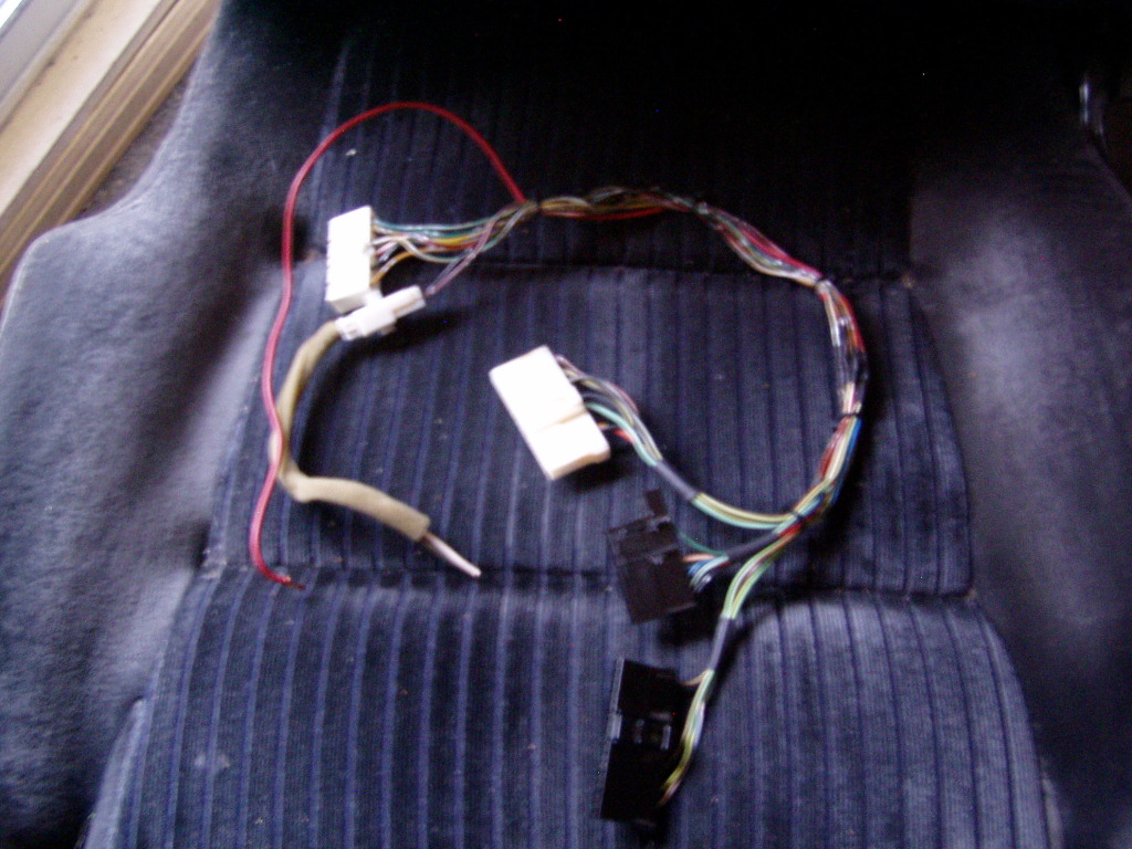
The loose red wire is the battery feed I've yet to connect, the unterminated two wire connector is the VSS signal feed.
The harness is about 8" longer than the stocker was- makes it easier to connect.
There's plenty of space behind the gauges, so there's no need to make life difficult.
I need to figure out what to sheath the VSS harness in.
It's a harsh environment under the car, I'd like to use something durable.
My thought now is to use a hard brake line.
Zizz off the flared ends and bend to fit the chassis, either adapt the clips for the speedo cable (one of which is broken...my bad!) or tie it to the real brake lines.
In a perfect world, the VSS would be part of the same harness that holds the Mazda transmission sensors but there's no way I'm doing that now, so the path of the original speedo cable it is.
Any other ideas about the VSS harness are welcome.

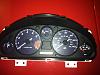
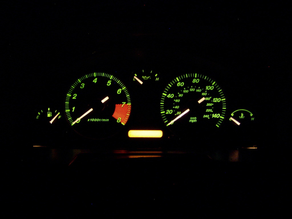
And Stage 1, done.
At this point, everything is functional.
Not necessarily accurate though.
The tach is spot on.
The speedo sweeps flawlessly, no glitches or hesitations but I'm guessing (with limited driving time so far) that it reads about 10% high.
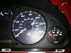
The fuel gauge (shown in the pic right after a fill up) has full sweep, although I suspect that true EMPTY will fall below the last hashmark.
The oil pressure gauge (like the water temp, connected to a VDO sending unit) is responsive but will need the needle repositioned. It now only moves between the lower markings.
Water temp sits just below halfway and does not waver. I may try the resistor mod to "free it up" or just go to a VDO.
So now I drive her around a bit and see how I like it.
I bought some Q-tips to retry the dial mod but am in no real hurry ATM.
At this point, everything is functional.
Not necessarily accurate though.
The tach is spot on.
The speedo sweeps flawlessly, no glitches or hesitations but I'm guessing (with limited driving time so far) that it reads about 10% high.
The fuel gauge (shown in the pic right after a fill up) has full sweep, although I suspect that true EMPTY will fall below the last hashmark.
The oil pressure gauge (like the water temp, connected to a VDO sending unit) is responsive but will need the needle repositioned. It now only moves between the lower markings.
Water temp sits just below halfway and does not waver. I may try the resistor mod to "free it up" or just go to a VDO.
So now I drive her around a bit and see how I like it.
I bought some Q-tips to retry the dial mod but am in no real hurry ATM.
After a night time drive, just a thought about the cluster lighting.
Ignore the color for now and concentrate on the clarity of display.
It is an order of magnitude better than the stock FC cluster and the whole reason is the FC's reliance on front diffused light for the dials and needles.
Of all the clusters I've examined in the junkyard, the FC is only one to use such a system and I suspect that's because the added complexity wasn't justified by the results.
As for the color, I found this green/white combo very easy on the eyes, quite easy to discern at a glance.
The later model white dial/red lighting Miata cluster would be a better aesthetic match to our switchgear but I find the "all red" night look hard to read, especially over longer periods of time.
Still think the Audi color scheme is the ideal, gotta work on that.
Steve is a hell of a guy. I used to race with him in SCCA every once in a while. I'm glad you had a great experience with him!
Your project is incredible, clokker! I'd like to do the same to my FC but unless you find a way to swap the cluster and recolor it to the orange-amber, I'm out. I like my colors. LOL.
Your project is incredible, clokker! I'd like to do the same to my FC but unless you find a way to swap the cluster and recolor it to the orange-amber, I'm out. I like my colors. LOL.
Then you're in luck, because the color change appears to be doable.
I experimented again on a dial and the Q-tip technique actually appears to work.
On the two large dials (tach/speedo) I estimate it'd take about an hour apiece to "degreen" them, small dials, maybe 15-20 minutes.
Once the graphics are down to white, simply inserting the proper colored filter between the diffuser and the dial would give the color of choice.
The red transparent sheet I bought at Hobby Lobby is a crap color filter.
Even multiple layers only resulted in a "rose" hue, not bold red.
More research needed in this area.
Hmmmm... I wonder if using gel filters a la photography equipment might give you the proper effect? I know that when I'm using gels I can get fairly bold results. i.e. turning a plain white wall red, yellow, green, etc.


im sorry, but WHY?
the cluster is one of the most unique, beautiful, interesting parts of the FC.. and you're replacing it with a generic one that looks almost identical to 98% of the grocery-getters on the road?
the cluster is one of the most unique, beautiful, interesting parts of the FC.. and you're replacing it with a generic one that looks almost identical to 98% of the grocery-getters on the road?
I think the FC cluster is atrocious and the Miata part a major upgrade.
And of course, the correct answer to "Why" is "Because it is there".
I thought everyone knew that.