
Lets see who knows about S5 ecus.....

Thread Starter
Joined: Sep 2005
Posts: 532
Likes: 1
From: Abilene, TX
Lets see who knows about S5 ecus.....
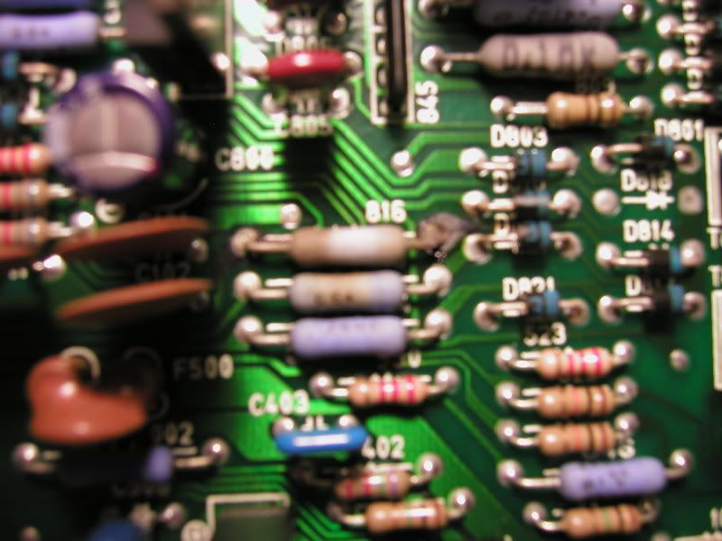
Got one here with some destroyed components. Wondering if anyone knows whats up. Problem started when I couldn't figure out why the tps adjustment didn't work. I check the three wires for voltage at the test connector and all three had 12v. That's obviously wrong since the black with a white stripe is the 12v source and the other two are the grounds for the lights. The grounds for the lights also happen to be pin 2P and pin 2O on the ECU which are the switching solenoid and relief solenoid control points ( where the ecu grounds the solenoids so they turn on or off ) basically there should never be 12v there. So I checked the car wiring for shorts. None to be had. Solenoids operate perfectly as well. Then I decided to check the ecu out since it had a feint smell of burnt electronics to it. I found the following definetely bad components
R816
R815
T805
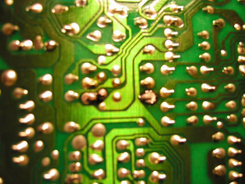
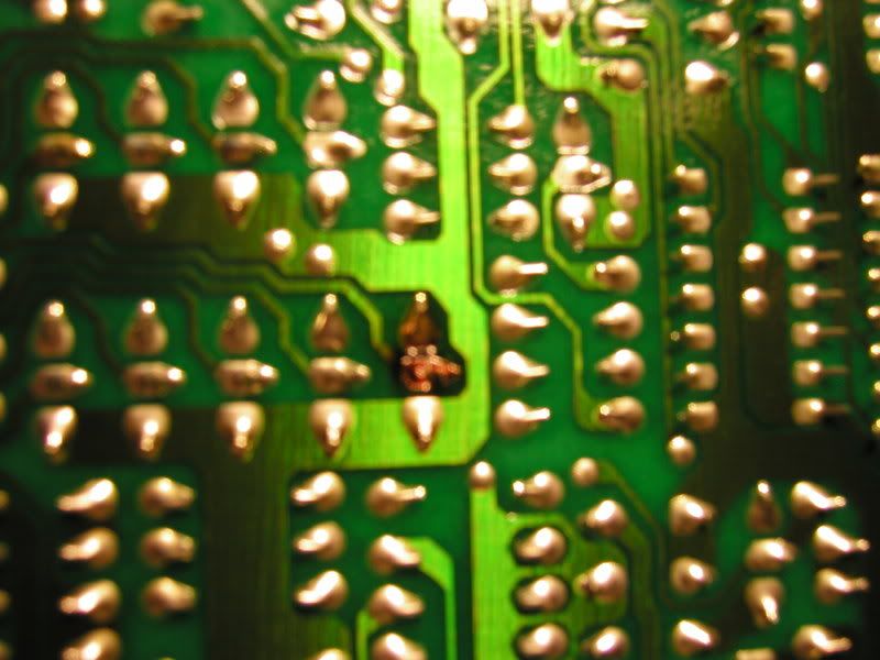
Trace from 816 to pin 2P slightly ruined
trace from other side of 816 to D814 (anode side) slightly ruined
Anyways just wanted to see if anyone knows why that happened or why it came like that I guess. Or if anyone fixes ecus. I am awaiting a return phone call from a guy that fixes hondas ecus to see if he wants to bother with it. If not I may try to take a crack at it. btw the car runs pretty damn good still for having a damaged ecu. I have another S5 ecu and it shows some wear in the same locations just isn't as bad. The ruined traces can be jumpered by small gauge wire but that's a bit ghetto. I am not going to attempt to repair the trace though since it's very hard to do. Here's a couple pictures of the damage.
Notice the discoloration of the two resistors it looks worse in person
R816
R815
T805
Trace from 816 to pin 2P slightly ruined
trace from other side of 816 to D814 (anode side) slightly ruined
Anyways just wanted to see if anyone knows why that happened or why it came like that I guess. Or if anyone fixes ecus. I am awaiting a return phone call from a guy that fixes hondas ecus to see if he wants to bother with it. If not I may try to take a crack at it. btw the car runs pretty damn good still for having a damaged ecu. I have another S5 ecu and it shows some wear in the same locations just isn't as bad. The ruined traces can be jumpered by small gauge wire but that's a bit ghetto. I am not going to attempt to repair the trace though since it's very hard to do. Here's a couple pictures of the damage.
Notice the discoloration of the two resistors it looks worse in person
Thread Starter
Joined: Sep 2005
Posts: 532
Likes: 1
From: Abilene, TX
Well i figured there would be no answer to this unless I asked for a opinion about what body kit to buy. I think I'll rob peter to pay paul and use the components out of one ecu to fix the other. If anyone comes up with anything let me know I'd like to hear of other problems the same as this.
BTW this could be due to the fact of someone hooking up some tail light bulbs to check the tps instead of using LEDs or very low amperage bulbs to keep from stressing the circuit. I use to of the little tiny gauge cluster V2 lamps personally.
Some of you may want to check your boards for damage due to the bigger bulbs. Just a thought. I only say so because I've seen a couple write ups saying you should use the 1157 or 1156 bulbs I can't remmber which but in either case you know what I'm talking about.
Also teh ECU displays the faults for the two solenoids mentioned above.
Former Moderator. RIP Icemark.
Joined: Apr 2001
Posts: 25,896
Likes: 24
From: Rohnert Park CA
Usually with that much damage to the protection resistors the Transistor drivers for the circuit are damaged too (as you found by a blown T805 - the BAC driver).
And yeah, I have tried matching resistance and using after market resistors and diodes, but it is usually still easier to just de-solder out undamaged resistors from another board and use them
And I don't know why anyone would use 35 watt bulbs to test anything... probably the same idiots that think test lights are safe.
Thread Starter
Joined: Sep 2005
Posts: 532
Likes: 1
From: Abilene, TX
Usually with that much damage to the protection resistors the Transistor drivers for the circuit are damaged too (as you found by a blown T805 - the BAC driver).
And yeah, I have tried matching resistance and using after market resistors and diodes, but it is usually still easier to just de-solder out undamaged resistors from another board and use them
And I don't know why anyone would use 35 watt bulbs to test anything... probably the same idiots that think test lights are safe.
And yeah, I have tried matching resistance and using after market resistors and diodes, but it is usually still easier to just de-solder out undamaged resistors from another board and use them
And I don't know why anyone would use 35 watt bulbs to test anything... probably the same idiots that think test lights are safe.
I have a S4 that has at least four of those resistors so I'll be stealing them from that one and then if I find a replacement I add those back to the S4 later to make it work again. I am even wondering if the little V2 lamps are inappropriate as well. Do you happen to know the type of light used on the factory tester? Or if anyone else does please leave an answer. I'm thinking they are LEDs but I've never seen the tester in person so I have just been using the V2s which are probably safe. Probably........
Thread Starter
Joined: Sep 2005
Posts: 532
Likes: 1
From: Abilene, TX
So on the factory tester both positives from the LEDs are to the black with a white stripe and each has a negative to the blue with a yellow stripe and othe blue with a red strip I imagine. At least on a S5 harness. I know the colors may differ on the S4 harness. I'll buy some LEDs then to be on the safe side since they don't cost anything anyways.
The car does run a bit diferent with either ECU so I'm wondering if theres further damage or its just the regular difference between ECUs due to the fact the tightest tolerance is within 5% from some components and most components are on the 10-20% rule. I think thats why most people don't understand why one guys tune dumped into anothers ECU dosen't run the engine exactly the same. Not to mention slight differences in the engines no matter how much you think they are identical.
Have you done anything with the ECUs on these cars? I've been talking to a good friend of mine who helped design Hondata about some of the stuff to see what he thinks and he says to replace some of the main caps on the board with new ones and a few other suggestions to be sure the power is appropriately be distributed and maintain. Possibly evn some of the transistors to be sure stuff works right. I don't realy want to go that far honestly since I think I may be one of the only people who cares about the factory ECU working right............
Former Moderator. RIP Icemark.
Joined: Apr 2001
Posts: 25,896
Likes: 24
From: Rohnert Park CA
So on the factory tester both positives from the LEDs are to the black with a white stripe and each has a negative to the blue with a yellow stripe and othe blue with a red strip I imagine. At least on a S5 harness. I know the colors may differ on the S4 harness. I'll buy some LEDs then to be on the safe side since they don't cost anything anyways.
The car does run a bit diferent with either ECU so I'm wondering if theres further damage or its just the regular difference between ECUs due to the fact the tightest tolerance is within 5% from some components and most components are on the 10-20% rule. I think thats why most people don't understand why one guys tune dumped into anothers ECU dosen't run the engine exactly the same. Not to mention slight differences in the engines no matter how much you think they are identical.
Have you done anything with the ECUs on these cars? I've been talking to a good friend of mine who helped design Hondata about some of the stuff to see what he thinks and he says to replace some of the main caps on the board with new ones and a few other suggestions to be sure the power is appropriately be distributed and maintain. Possibly evn some of the transistors to be sure stuff works right. I don't realy want to go that far honestly since I think I may be one of the only people who cares about the factory ECU working right............
The car does run a bit diferent with either ECU so I'm wondering if theres further damage or its just the regular difference between ECUs due to the fact the tightest tolerance is within 5% from some components and most components are on the 10-20% rule. I think thats why most people don't understand why one guys tune dumped into anothers ECU dosen't run the engine exactly the same. Not to mention slight differences in the engines no matter how much you think they are identical.
Have you done anything with the ECUs on these cars? I've been talking to a good friend of mine who helped design Hondata about some of the stuff to see what he thinks and he says to replace some of the main caps on the board with new ones and a few other suggestions to be sure the power is appropriately be distributed and maintain. Possibly evn some of the transistors to be sure stuff works right. I don't realy want to go that far honestly since I think I may be one of the only people who cares about the factory ECU working right............
Usually when I change burnt stuff I try to do 5% for the replacement parts.
Trending Topics
Wire monkey
Joined: Nov 2006
Posts: 74
Likes: 0
From: Camberley, Surrey, UK
Another thing to bear in mind is these are power resistors (1W probably), and may get warm during operation. It's not a bad idea to space them off the PCB just a little when you solder in a replacement, as it allows better airflow around the component, and prevents scorching of the PCB.
Thread Starter
Joined: Sep 2005
Posts: 532
Likes: 1
From: Abilene, TX
Another thing to bear in mind is these are power resistors (1W probably), and may get warm during operation. It's not a bad idea to space them off the PCB just a little when you solder in a replacement, as it allows better airflow around the component, and prevents scorching of the PCB.
Unfortunetaly we took the resistors from a S4 ECU and so we didn't have new leads to work with but did the best we could.
The ECU is fully functional again now. We DID NOT fix the ECU with the bad transistor yet as my friend is still looking up the possible replacement if its not obtainable anymore. It will get fixed though.
The one with just two damaged resistors mentioned above is repaired by just replacing the resistors. I warmed the car up and adjusted the TPS as per the factory manual. Everything worked fine. I have one very slight other problem unrelated to damage on the ECU. It's that the engine is slow to return to idle. It hangs out just above 1000rpm then kinda makes its way to 1000 rpm eventually and will go no ower. Although I don't have a test tach to see if it really is 1000rpm or if its lower. It sounds lower to me but the engine is a bit decieving judging on noise alone. I think the transistor for the BAC may be weak and we are going to replace it when we find the appropriate one. I suck at looking stuff up on digikey so I'm leaving up to my buddy to do for now.
Also I made the test lights with LEDs now I like it better since its instantly on and off at the cut off points instead of slowly getting a bit brighter and dimmer at the edges.
We are also going to figure out teh correct resistence for the resistors used to be able to buy brand new replacements and I'll post all findings here so anyone that cares can have the info