
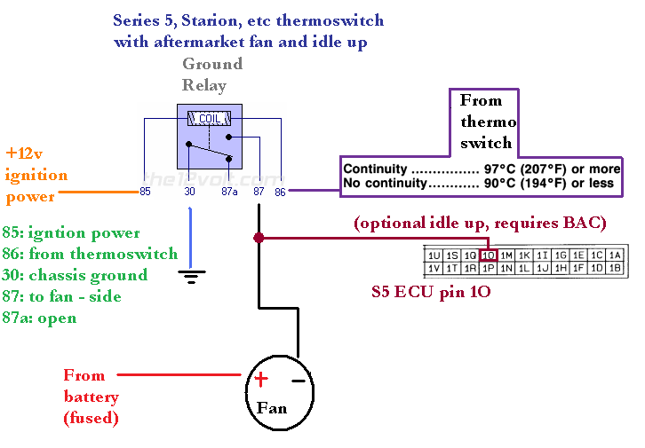
HOW TO: Control an electric fan with a factory thermoswitch


And on the subject can i use a thermoswitch from the vehicle i take the fan out of?
Drawing up a diagram is where my problems will start. I understand enough to get the larger concepts, but I don't know enough to draw up diagrams. I'll spend some time researching the power antenna relay and reversing polarity. It can't be that difficult.......right???
Download the wiring diagrams from the FSM. The first pages explain what all the symbols mean and show you how to read the diagrams. Look through the factory diagrams and look at how I drew up mine. Then try to put something together and post it up so others can look at it. It took me a while to understand wiring diagrams. I learned from studying Mazda diagrams and also I learned hands-on from a technician friend and a car audio/security installer friend.
I'm not sure. I'd have to see it. I'll admit my experience with s5 systems in general is limited, beyond what is in the service manuals. There really aren't that many s5 cars around anymore. If you have a thermoswitch are you sure
If you're not at the level where you can draw a diagram, you're probably not ready to take on a custom setup yet. A diagram isn't there to look pretty even though I tried to make mine somewhat nice. It's there so you understand how the system works and you can keep track of what all the wires should be doing.
Download the wiring diagrams from the FSM. The first pages explain what all the symbols mean and show you how to read the diagrams. Look through the factory diagrams and look at how I drew up mine. Then try to put something together and post it up so others can look at it. It took me a while to understand wiring diagrams. I learned from studying Mazda diagrams and also I learned hands-on from a technician friend and a car audio/security installer friend.
I have spent time with FSM wiring diagrams but still struggle with understanding them. My problem is something you referenced about learning hands-on thru friends. I unfortunately live in a bubble, no friends have any electronics experience to speak of. Couple that with me being VERY hands on learner. I'm a visual learner and need things in my hands. Wiring diagrams are too abstract, but once I have tangible objects to visually connect the dots I'm good.
I've drawn up basic diagrams for installing car alarm door actuators on my vert. So I do have some experience...but it's rough knowledge. I did the same thing for doing my power antenna. But that was over 10 yrs ago for the antenna. Since I first did the antenna I've simply duplicated where the wires connected on my 2nd vert. But it can't be that hard to find a diagram for the power antenna polarity reversal and apply that to the factory switch wiring. It's a basic on/off so once the ECU has the ground signal it needs I should be good....or am I over simplifying?
I've drawn up basic diagrams for installing car alarm door actuators on my vert. So I do have some experience...but it's rough knowledge. I did the same thing for doing my power antenna. But that was over 10 yrs ago for the antenna. Since I first did the antenna I've simply duplicated where the wires connected on my 2nd vert. But it can't be that hard to find a diagram for the power antenna polarity reversal and apply that to the factory switch wiring. It's a basic on/off so once the ECU has the ground signal it needs I should be good....or am I over simplifying?

You've got the trigger wire, the polarity you start with. That can go to the 86 pin. Think of that as the relay input. Then you have the output wire, the wire that will be driving something in the circuit. That can be the 30 pin. Finally, you need a source for the reversed polarity.
If I am changing a constant +12V from the battery (86 pin) to a constant ground, I would run a chassis ground wire to the 85 and 87 pins. If I am changing a constant ground (86 pin) to a constant +12V from the battery, I would run two +12V wires from the battery to the 85 and 87 pins. Regardless of the polarity you are changing, you could run one wire intended for the 87 pin most of the way and then splice into it for the 85 pin right near the relay.
Well I feel small. This whole time I was thinking that like the antenna I would need to reverse polarity on the Summit switch for the ECU to read it. I got myself confused with the difference between S4 and S5.
I believe my needs are much simpler. Split the signal coming off the Summit switch. One goes to the engine harness the other goes to the relay for the efan.
I believe my needs are much simpler. Split the signal coming off the Summit switch. One goes to the engine harness the other goes to the relay for the efan.
So backtracking a little. If I'm using the Summit 200deg switch. I can use the original S5 diagram
86 is Summit 200deg
Can I then do 87 and have BOTH (-)fan and into engine harness for the OEM switch?
Or is another possibility to use 87a for the OEM switch wiring?
As a side note, I'm frustrated enough with NOT knowing electronics I'm stopping by a Radio Shack to see about getting a kids electronic building kit.
You're trying to keep the factory aux fan right? I'm confused now. If the factory aux fan and thermoswitch are installed and working correctly, just leave that circuit alone.
Maybe I'm not understanding your question, but I don't see why you can't use the diagram exactly the way its drawn without modification. It sounds like the Summit switch should provide continuity to ground at 200F. So yes you would have a heavier gauge wire come off pin 87 and run to the - side of the fan. You can splice an 18 gauge wire into that and tap it into the correct pin for idle up (s4 is 1E s5 is 1O).
You're trying to keep the factory aux fan right? I'm confused now. If the factory aux fan and thermoswitch are installed and working correctly, just leave that circuit alone.
You're trying to keep the factory aux fan right? I'm confused now. If the factory aux fan and thermoswitch are installed and working correctly, just leave that circuit alone.
I will give you a hint. You need to look at page Z-80 of the S5 wiring diagrams, and take a look at page F1-40 of fuel and emissions control (s5 non turbo) section.
Thanks, I've scanned through the cooling section and wiring diagram section. But was sitting at a coffee shop partially distracted and no pen to take notes. I haven't looked through fuel and emissions yet.
If I'm understanding things correctly simply following the S5 diagram and taping into the 1O on the ecu will accomplish the same thing that the OEM wiring did for the OEM switch. Only at 7deg lower.
My next question is simply for the sake of understanding. Are there two sources for idle increase related to A/C? There is the A/C switch on F1-40 which increases idle when the aux fan comes on. Is there a separate idle increase for the A/C compressor turning on? Or is the only source for idle increase related to A/C that OEM switch?
I'm just curious why the OEM switch and wiring are there if I don't have the aux fan on the A/C. I've owned two verts and both of them have that switch and neither of them has/had that aux fan on the A/C. Is it simply for redundancy (for lack of a better word), so that an owner can go in a dealership and tell them to put an aux fan on and make things that much easier for the dealership to do it?
Lastly, not to throw a monkey wrench in all of this. But I found another thermoswtich related to A/C in the S5 Cooling and Heating section. It's on U3 and U37 and it's item #3. Following to U-45 shows testing continuity for very low temps 38-40.
If I'm understanding things correctly simply following the S5 diagram and taping into the 1O on the ecu will accomplish the same thing that the OEM wiring did for the OEM switch. Only at 7deg lower.
My next question is simply for the sake of understanding. Are there two sources for idle increase related to A/C? There is the A/C switch on F1-40 which increases idle when the aux fan comes on. Is there a separate idle increase for the A/C compressor turning on? Or is the only source for idle increase related to A/C that OEM switch?
My next question is simply for the sake of understanding. Are there two sources for idle increase related to A/C? There is the A/C switch on F1-40 which increases idle when the aux fan comes on. Is there a separate idle increase for the A/C compressor turning on? Or is the only source for idle increase related to A/C that OEM switch?
I'm just curious why the OEM switch and wiring are there if I don't have the aux fan on the A/C. I've owned two verts and both of them have that switch and neither of them has/had that aux fan on the A/C. Is it simply for redundancy (for lack of a better word), so that an owner can go in a dealership and tell them to put an aux fan on and make things that much easier for the dealership to do it?
Lastly, not to throw a monkey wrench in all of this. But I found another thermoswtich related to A/C in the S5 Cooling and Heating section. It's on U3 and U37 and it's item #3. Following to U-45 shows testing continuity for very low temps 38-40.
Sorry to interrupt here fellas.... On a different note, if i wished to wire in a manual override to control the fan I would simply have to place a on-off-on toggle that switched ground between continuity provided by the stock temp sensor and actual ground, yes?
On an S5, yes. Or, if you're using arghx's S4 diagram, you want the switch to interrupt the connection to the thermoswitch, just as in my single-relay diagram.
My original picture has disappeared, but it illustrates the use of an SPST switch to manually turn the fan on. Here it is again, or perhaps some wonderful moderator could edit my original post as well.

Larger Image
My original picture has disappeared, but it illustrates the use of an SPST switch to manually turn the fan on. Here it is again, or perhaps some wonderful moderator could edit my original post as well.
Larger Image
So here's something interesting. It turns out that the Mark IV Supra has a thermoswitch that engages at 208F/98C. This is in addition to a clutch fan.

The thermoswitch is actually located at the bottom of the radiator.
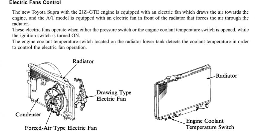
The whole system looks pretty similar to what's on the FC.
The thermoswitch is actually located at the bottom of the radiator.
The whole system looks pretty similar to what's on the FC.
Just wanted to add something relevant and useful to the thread. Here's my schematic for wiring a 2-speed Taurus fan the proper way on a S4 using the OEM thermoswitch. The red relay has to be a high current one since it operates the high speed mode. The only thing I couldn't figure out was to only use the idle-up function when the hi-speed mode was active, so I left it always on.

these have to be 5 pin relays correct?
only the changeover and ground relays would need to be a 5-pin ones (connected to pin 87A). S4 thermoswitches turn OFF at their set temperature, while S5 ones turn ON at the set temperature
Last edited by Akagis_white_comet; Jul 21, 2011 at 02:47 PM. Reason: corrected information
What year/model Subaru was it? And yes, if anyone knows of any other switches that have the same threads and ground at a decent temperature, post them up, please!
Ok, I'm doing something wrong here.... somebody help me out:
I've got everything wired up per arghx's first diagram for the s4 temp switch to turn on my 40amp Volvo electric fan. I am drawing 12v switched power for the relays from the B/W wire on the green 6-pin check connector near the leading coils. I have a 12V lamp set up in my A-pillar to let me know when the fan is running, the lamp has a ground spliced into the ground for the fan, spliced right off of the fan. The lamp draws power from the cigarette lighter. So, that's all that has been modified from the diagram...
I AM MELTING RELAYS. Just found out the other day driving around, the lamp was on but the fan wasn't running. I checked the relays and found the terminal for 87, on the "hot relay", was melted and not making connection. Yesterday I undid my harness and found that terminal 87a on the "ground relay" was also melted to ****???
I didn't think ground carried any current??? How the heck was that one melted too???
Anyways, I found that the wires that were coming off of the fan were corroded, both hot and ground. I'm assuming that this is what caused the resistance in line that melted everything... can somebody give me some feedback on this?
Also, when I disconnect the temp switch from the circuit, the fan comes on, but that's due to the fact that when you do that you basically remove that relay from the equation and the hot relay gets grounded, right?
It has been suggested that I run a 5amp fuse inline from the 12v switched source to the relays as well, any thoughts?
And lastly, Having that lamp wired up isn't messing with anything is it? I'm thinking it would be a better idea to splice the hot lead into the fan hot as well that way it would function better as a safety notification that the fan is on, but then wouldn't the 40amps that the fan is pulling kill that little lamp? I'm not sure...
Thanks for the time, pardon my ignorance in wiring, yes everything is wired per the diagram correctly. I'm may be overthinking things, but I'm paranoid seeing as how I don't want to overheat, losing two engines that way in my life already.
Joined: Apr 2005
Posts: 3,785
Likes: 30
From: And the horse he rode in on...
Ok, I'm doing something wrong here.... somebody help me out:
I've got everything wired up per arghx's first diagram for the s4 temp switch to turn on my 40amp Volvo electric fan. I am drawing 12v switched power for the relays from the B/W wire on the green 6-pin check connector near the leading coils. I have a 12V lamp set up in my A-pillar to let me know when the fan is running, the lamp has a ground spliced into the ground for the fan, spliced right off of the fan. The lamp draws power from the cigarette lighter. So, that's all that has been modified from the diagram...
I AM MELTING RELAYS. Just found out the other day driving around, the lamp was on but the fan wasn't running. I checked the relays and found the terminal for 87, on the "hot relay", was melted and not making connection. Yesterday I undid my harness and found that terminal 87a on the "ground relay" was also melted to ****???
I didn't think ground carried any current??? How the heck was that one melted too???
Anyways, I found that the wires that were coming off of the fan were corroded, both hot and ground. I'm assuming that this is what caused the resistance in line that melted everything... can somebody give me some feedback on this?
Also, when I disconnect the temp switch from the circuit, the fan comes on, but that's due to the fact that when you do that you basically remove that relay from the equation and the hot relay gets grounded, right?
It has been suggested that I run a 5amp fuse inline from the 12v switched source to the relays as well, any thoughts?
And lastly, Having that lamp wired up isn't messing with anything is it? I'm thinking it would be a better idea to splice the hot lead into the fan hot as well that way it would function better as a safety notification that the fan is on, but then wouldn't the 40amps that the fan is pulling kill that little lamp? I'm not sure...
Thanks for the time, pardon my ignorance in wiring, yes everything is wired per the diagram correctly. I'm may be overthinking things, but I'm paranoid seeing as how I don't want to overheat, losing two engines that way in my life already.
I've got everything wired up per arghx's first diagram for the s4 temp switch to turn on my 40amp Volvo electric fan. I am drawing 12v switched power for the relays from the B/W wire on the green 6-pin check connector near the leading coils. I have a 12V lamp set up in my A-pillar to let me know when the fan is running, the lamp has a ground spliced into the ground for the fan, spliced right off of the fan. The lamp draws power from the cigarette lighter. So, that's all that has been modified from the diagram...
I AM MELTING RELAYS. Just found out the other day driving around, the lamp was on but the fan wasn't running. I checked the relays and found the terminal for 87, on the "hot relay", was melted and not making connection. Yesterday I undid my harness and found that terminal 87a on the "ground relay" was also melted to ****???
I didn't think ground carried any current??? How the heck was that one melted too???
Anyways, I found that the wires that were coming off of the fan were corroded, both hot and ground. I'm assuming that this is what caused the resistance in line that melted everything... can somebody give me some feedback on this?
Also, when I disconnect the temp switch from the circuit, the fan comes on, but that's due to the fact that when you do that you basically remove that relay from the equation and the hot relay gets grounded, right?
It has been suggested that I run a 5amp fuse inline from the 12v switched source to the relays as well, any thoughts?
And lastly, Having that lamp wired up isn't messing with anything is it? I'm thinking it would be a better idea to splice the hot lead into the fan hot as well that way it would function better as a safety notification that the fan is on, but then wouldn't the 40amps that the fan is pulling kill that little lamp? I'm not sure...
Thanks for the time, pardon my ignorance in wiring, yes everything is wired per the diagram correctly. I'm may be overthinking things, but I'm paranoid seeing as how I don't want to overheat, losing two engines that way in my life already.
I have melted some fan relays in my day, so I may be able to help.
What gauge wiring are you using on the current carring wires? You need minimum 10 gauge. I use 8 ga these days. You should use 10 or 8gauge on 87, 87a and 30 terminals. They all carry high current when used on a relay.
Is your relay using a 1/4" lug? That size lug is technically limited to 30 amps. If your fan is pulling above 30 amps, then you will have trouble. The heat will corrode the connection, increasing resistance until the relay melts. I don't know if the Volvo fan pulls that much current, don't think it does. Probably the wiring, see above.
Are you using a socket that came with the relay? None of those sockets are capable of handling a cooling fan current. I no longer use that type of socket.
I have found that a 1/4" lug is rated to carry 30 amps. There is a relay that has 3/8" on the 30, 87 and 87a terminals.. That relay is rated to 60 amps. I would use one if I was starting over, but since i bought my original Bosch/Tyco relays in bulk, I am using what I have.
I also changed from the Mighty Lincoln Mark VIII fan to a Mercury Villager fan. It pulls less current than the Mark VIII.
You could use an OEM volvo relay...https://www.rx7club.com/showthread.php?t=920978...I have one but do not use it because there is no provision for turning on the fan with the A/C. I could get creative with it, but my setup is pretty bulletproof right now, so I haven't messed with the Volvo relay.
I can't remember where I read it or heard it, but I believe the fan i have draws 40 amps? I've got relays rated at 40 amps, but the wires are definitely 12gauge, except for the hot lead to the battery, and the lugs are 1/4"... so then... I'm definitely getting some new relays tomorrow anyways, I'll look for a bigger one when i go to the supply shop. I'd pick up that Volvo relay off of you, but the way this switch works I need two relays.
As for sockets, I wasn't even using a socket, truthfully, I used plastic shielding on the crimped connectors and then taped the whole thing up.
As for sockets, I wasn't even using a socket, truthfully, I used plastic shielding on the crimped connectors and then taped the whole thing up.

I have a 86 S4 manual(ac has been removed), my oem rad had thermo switch but wire was broken off. Does any one know how I can find the wire and recoonect? If i change over to koyo rad, the have the spot with the threads, do i need the thermo swith on this s well?