
Thermostat/EFan Question

Thermostat/EFan Question
Ok, so I'm doing the e-fan mod on my car and I really want to go about it the right way, using a thermostat to switch it on and off (as opposed to having it run constantly or manually via a switch in the dash). I'm pretty much going by Aaron's wiring diagram. I just removed the A/C Condenser and stock Electrical Fan.
My question is this- I know the stock EFan is set to come on at 207 degrees, is there anyway to use the wiring for that in lieu of an aftermarket thermostat? would that work physically, and also is 207 degrees too high for that application. (I know our cars are supposed to run at about 190)
I've also got what appears to be a thermostat/fan switch threaded into a bung on the lower passenger side of my radiator. Looks just like this:
http://shop.advanceautoparts.com/web...S_575748549___
I can't seem to find it in the FSM. What is it's purpose, and if it is a fan switch does anybody know what temperature it might be set to? Would this work for my application?
Or am I just going to have to get an aftermarket thermostat/fan switch?
Thanks
Joined: Sep 2005
Posts: 25,581
Likes: 136
From: Smiths Falls.(near Ottawa!.Mapquest IT!)
That thing on the bottom of the rad is a sensor for the ECU.(two prong bullet connector Thingie)
If you need to put in a thermoswitch,then it would be better to tap the back of the waterpump housing,or maybe use a 'probe type" sensor attached in the fins of the rad to tell the Efan to turn on.
That is just my opinion,as there are many other alternatives..more guys should be Chiming in shortly..(but it's a start!)
If you don't want to deal with the housing, the second best option is a fitting in the upper rad hose.
I guess I'm just going to have to tap into the waterpump housing then.
K-Tune:
Looking at the thermo fan switch from a Starion it only has one connector (as opposed to two). This may seem like a stupid question but how exactly does the actual "switching" function work with only one prong?
K-Tune:
Looking at the thermo fan switch from a Starion it only has one connector (as opposed to two). This may seem like a stupid question but how exactly does the actual "switching" function work with only one prong?
Trending Topics


Hold on. There's some confusion here. The short answer is that there are three FC thermoswitches available and all will work for you if you know how to wire them up. I think I may do a writeup in a separate thread which will explain how the electric fan control system works on the FC, both series 4 and 5.
Hold on. There's some confusion here. The short answer is that there are three FC thermoswitches available and all will work for you if you know how to wire them up. I think I may do a writeup in a separate thread which will explain how the electric fan control system works on the FC, both series 4 and 5.
the starion switch "makes" when the temperature reaches 190 degrees. if the ground of the relay is connected to it the relay will not cross-over until the sensor reaches 190 degrees. when the temp falls below 190 degrees the relay and fan turn off...
the ground is gained through the body of the sensor..so if your engine is grounded properly it will work properly.
i didn't really like the way any of the stock sensors "made and broke" so i got the starion as it was perfect for what i wanted and cheap...it's the one found in the radiator of a starion and fits in our thermostat housing.
Hold on. There's some confusion here. The short answer is that there are three FC thermoswitches available and all will work for you if you know how to wire them up. I think I may do a writeup in a separate thread which will explain how the electric fan control system works on the FC, both series 4 and 5.
To the OP:
When using an aftermarket switch, the thermostat housing location is perfect. The stock hole can be chased with a 3/8" pipe thread tap to fit almost any aftermarket switch. Don't bother with the corner radiator location, since that doesn't actually allow contact with the water & it's at the "cold" half of the radiator. The switch will trigger way too late there.
Trust me man, I know Rx-7 fan control systems very well. I've already done a thorough article on the FD fan system: https://www.rx7club.com/3rd-generation-specific-1993-2002-16/why-engine-so-damn-complicated-part-3-cooling-fan-controls-876767/
Series 4 non turbo A/T 195F/90C , normally closed ground, spade connector
Series 4 turbo 207F/97C , normally closed ground, spade connector
Series 5 (all) 207F/97C , normally open ground, FD style connector
Series 6 (all) 226F/108C, normally open ground, FD thermoswitch (same connector as series 5 but insanely high temperature)
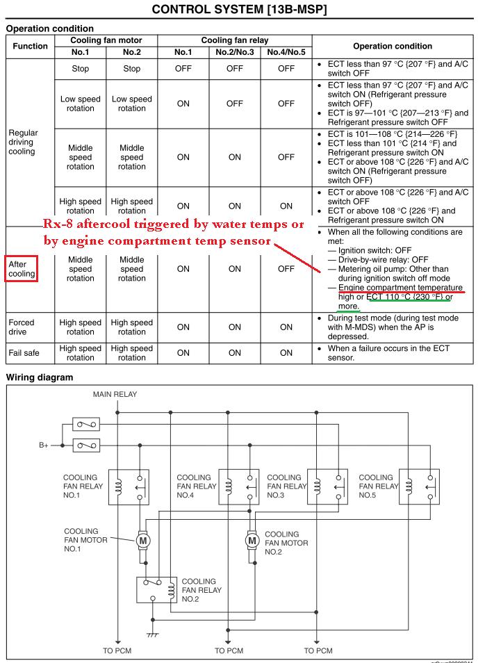
207F/97C isn't that high. That's the exact temperature that the Rx-8 PCM turns on their fans. There are thousands and thousands of Rx-8's running at that temperature every day and those cars are not known for coolant seal problems.
Anyway, the FC 207F/97C thermoswitch is actually a mod for the FD, as their fans don't normally come on until 105C/221F. And people run that hot all day long. Seriously.
Remember that the thermostat isn't even fully open until 203F/95C. Also, according to the FSM there is a hysteresis function in the thermoswitch where the fan will come on at 207F/97C but won't turn back off until 195F/90C. The advantage of a fan that triggers at a higher temperature is that you aren't constantly drawing all the current on the shitty FC electrical system. In the winter the fan hardly comes on at all.
There's also the s4 nonturbo thermoswitch which initially triggers at 195F/90C and I imagine cuts off at about 85C, not sure though as it is not discussed in the FSM.
See http://www.mazdatrix.com/86-92Electrical-Engine.htm
Also see s4 FSM 3-15, s5 FSM E-13
I'm working on a very thorough writeup right now that will discuss how to use the normally closed pin on a relay (pin 87a) to trigger a fan with an s4 thermoswitch. It will also show how to integrate the factory A/C idle up function for the BAC valve.
Originally Posted by RotaryRocket88
Which ones were you thinking of? Only the thermoswitches could be used to ground a relay & turn a fan on.
Series 4 turbo 207F/97C , normally closed ground, spade connector
Series 5 (all) 207F/97C , normally open ground, FD style connector
Series 6 (all) 226F/108C, normally open ground, FD thermoswitch (same connector as series 5 but insanely high temperature)
207F/97C isn't that high. That's the exact temperature that the Rx-8 PCM turns on their fans. There are thousands and thousands of Rx-8's running at that temperature every day and those cars are not known for coolant seal problems.
Anyway, the FC 207F/97C thermoswitch is actually a mod for the FD, as their fans don't normally come on until 105C/221F. And people run that hot all day long. Seriously.
Remember that the thermostat isn't even fully open until 203F/95C. Also, according to the FSM there is a hysteresis function in the thermoswitch where the fan will come on at 207F/97C but won't turn back off until 195F/90C. The advantage of a fan that triggers at a higher temperature is that you aren't constantly drawing all the current on the shitty FC electrical system. In the winter the fan hardly comes on at all.
There's also the s4 nonturbo thermoswitch which initially triggers at 195F/90C and I imagine cuts off at about 85C, not sure though as it is not discussed in the FSM.
See http://www.mazdatrix.com/86-92Electrical-Engine.htm
Also see s4 FSM 3-15, s5 FSM E-13
I'm working on a very thorough writeup right now that will discuss how to use the normally closed pin on a relay (pin 87a) to trigger a fan with an s4 thermoswitch. It will also show how to integrate the factory A/C idle up function for the BAC valve.
Series 4 non turbo A/T 195F/90C , normally closed ground, spade connector
Series 4 turbo 207F/97C , normally closed ground, spade connector
Series 5 (all) 207F/97C , normally open ground, FD style connector
Series 6 (all) 226F/108C, normally open ground, FD thermoswitch (same connector as series 5 but insanely high temperature)
207F/97C isn't that high. That's the exact temperature that the Rx-8 PCM turns on their fans. There are thousands and thousands of Rx-8's running at that temperature every day and those cars are not known for coolant seal problems.
I just pulled the diagrams, I need to look over them again. I see what you are saying. On the ECU side (idle up) it doesn't matter because the ECU is triggered by the main relay anyway. The fan itself needs to be switched somehow (either on the power or the ground side), but I don't want this to turn into something complicated that requires yet another relay. Is there a higher amperage switched power or ground for the fan that we could tap into? Maybe power the fan right off the big connections in the bottom of the fuse box? Or are those constant power only? Maybe there's another way to wire up these relays. I don't want 3 relays, few will bother with that.
The series 4 thermoswitches are a pain. On the s5 it's easier.
The series 4 thermoswitches are a pain. On the s5 it's easier.
Well the s5 and s6 thermoswitches work just like the Starion's. That's why I said earlier that using the s5 is a lot easier... normal 4 pin relay wiring and you're done. But as a personal challenge I figured out how to control the fan and the idle up this using the factory s4 thermoswitch and only two relays.
So here is the revised diagram for series 4. There are two relays. One controls fan power and one controls fan ground. With the key off, the fan will have ground but it will not have power. With the key on, the fan will have power but it will not have ground until the thermoswitch trigger temperature is reached. When the trigger temperature is reached, the thermoswitch will "remove" the signal to pin 86 of the ground relay. The chassis ground will be supplied to the fan through pin 87a, the normally closed pin. The fan will stay on until temps drop down below 195F/90C if you have a turbo thermoswitch. If you have an s4 nonturbo A/T thermoswitch, the ON and OFF temps will be lower.

It may look complicated, but that's about as simple as you're going to get using easily available relays. I tried to use splices and shared wires. The idle up function is achieved by sending a ground to s4 ECU pin 1E (same on turbo and non turbo) which will make the ECU think that the A/C is on. That will increase BAC valve duty cycle (more idle air) and advance the ignition timing from -5L -20T to 10L 10T, per the training manual.
For the sake of a future writeup I would appreciate it if the OP can test this full setup for me, including idle up. I do know that at least one guy has done the idle up before, I remember helping him figure out the wiring. I would test this myself but I already have a Power FC which triggers my fan and idle up based on the water temperature reading from the thermosensor.
So here is the revised diagram for series 4. There are two relays. One controls fan power and one controls fan ground. With the key off, the fan will have ground but it will not have power. With the key on, the fan will have power but it will not have ground until the thermoswitch trigger temperature is reached. When the trigger temperature is reached, the thermoswitch will "remove" the signal to pin 86 of the ground relay. The chassis ground will be supplied to the fan through pin 87a, the normally closed pin. The fan will stay on until temps drop down below 195F/90C if you have a turbo thermoswitch. If you have an s4 nonturbo A/T thermoswitch, the ON and OFF temps will be lower.
It may look complicated, but that's about as simple as you're going to get using easily available relays. I tried to use splices and shared wires. The idle up function is achieved by sending a ground to s4 ECU pin 1E (same on turbo and non turbo) which will make the ECU think that the A/C is on. That will increase BAC valve duty cycle (more idle air) and advance the ignition timing from -5L -20T to 10L 10T, per the training manual.
For the sake of a future writeup I would appreciate it if the OP can test this full setup for me, including idle up. I do know that at least one guy has done the idle up before, I remember helping him figure out the wiring. I would test this myself but I already have a Power FC which triggers my fan and idle up based on the water temperature reading from the thermosensor.
Dunno if this helps but I have a SPAL fan and it is awesome. Comes with all the hardware to mount the fan, wire, etc. It is set to come on at 180degrees. I have not had any problems with it, my sensor is tapped in the back of the water pump housing as well. Awesome fan super easy install, would recommend it to anyone.
Trust me man, I know Rx-7 fan control systems very well. I've already done a thorough article on the FD fan system: https://www.rx7club.com/showthread.php?t=876767
Series 4 non turbo A/T 195F/90C , normally closed ground, spade connector
Series 4 turbo 207F/97C , normally closed ground, spade connector
Series 5 (all) 207F/97C , normally open ground, FD style connector
Series 6 (all) 226F/108C, normally open ground, FD thermoswitch (same connector as series 5 but insanely high temperature)
207F/97C isn't that high. That's the exact temperature that the Rx-8 PCM turns on their fans. There are thousands and thousands of Rx-8's running at that temperature every day and those cars are not known for coolant seal problems.
And 207F isn't excessively high, but it's also needlessly high when compared to the thermostat opening point (~177-182F). Having the fan run long after the engine reaches operating temp is just going to introduce added heat to the engine bay & potentially cause cooling problems on very hot days. I know Mazda thought it would be great to overheat the FD, but the FC clutch fan locks up at a much lower temperature. I've been trying to find the exact numbers, but it is at least partially locked up by thermostat opening temp.
I have discussed the fan clutch before, actually in that article on 3rd gen cooling systems.
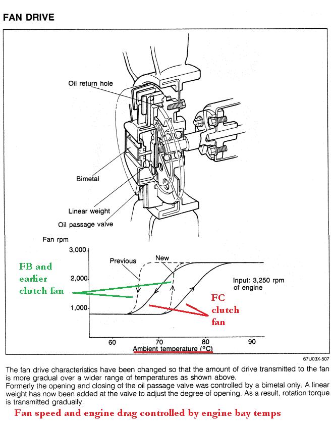
The FC clutch fan begins to engage when the fluid inside reaches about 72 C or 161 F. No engine coolant is supplied to the fan clutch, so it is dependent on radiant engine bay heat and conductive heat from the engine block. Since that can vary with the weather, it's not the most precise method of control, but it does offer progressive fan speed. Only the pulsewidth modulated electric fans throttle the speed like that, such as the ones that come stock on EVO's.
I think 97C/207F is a little bit higher than I would prefer, but remember that the non turbo s4 thermoswitches engage at 90C/195F according to Mazdatrix. 90C is the temperature at which I turn on my e fan with my Power FC. 97C trigger temps aren't going to hurt anything though, and remember that the fan will then stay on until temps drop to 90C/195F. You won't notice much of a difference with the 97C/207F trigger temp--again, that's the same temps that Rx-8s run at. And those cars have 100k mile engine warranties.
So if you don't like the 97C thermoswitches, you can use the s4 non turbo one or the Starion one. It won't hurt my feelings. All of these options are better than flipping a switch or using those stupid radiator probes or other controllers that feed off the signal from a coolant temp gauge. And hooking in the idle up function will reduce the voltage drop, especially at night when you have the headlights on.
For the sake of a future writeup I would appreciate it if the OP can test this full setup for me, including idle up. I do know that at least one guy has done the idle up before, I remember helping him figure out the wiring. I would test this myself but I already have a Power FC which triggers my fan and idle up based on the water temperature reading from the thermosensor.
yeah if you notice anything weird, there's another way to wire it up so let me know. basically you would just run one relay to invert the s4 thermosensor signal to the s5/Starion style signal. Then the other relay would be just like any other fan relay. It would be the same amount of wires really.
Joined: Apr 2005
Posts: 3,785
Likes: 30
From: And the horse he rode in on...
yeah that sounds familiar. I remember wondering to myself whether pin 1E needed to see +12V normally (without the idle up) and he figured out that it didn't. it just needs to see ground on that pin to work right.