Help identifying a switched power source under the hood?
 05-10-12, 08:32 PM
#1
Senior Member
Thread Starter

Join Date: Jul 2005
Location: Orlando, FL
Posts: 566
Likes: 0
Received 0 Likes
on
0 Posts
Help identifying a switched power source under the hood?
Guys, I'm looking for a switched power source to power up a 70/80 amp relay under the hood. Any pics or diagrams? This is to run the Taurus E fan on high once the ignition is opened. Thanks


 05-10-12, 10:39 PM
#6
Retired Moderator, RIP
iTrader: (142)
Join Date: Sep 2005
Location: Smiths Falls.(near Ottawa!.Mapquest IT!)
Posts: 25,581
Likes: 0
Received 131 Likes
on
114 Posts
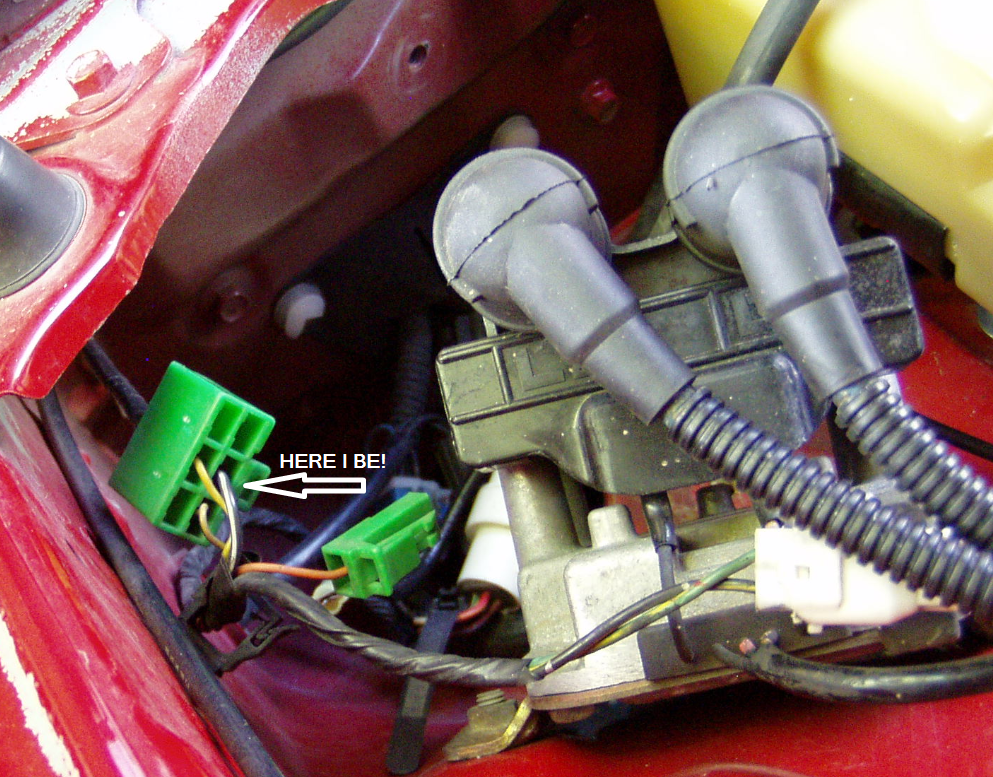
6 pin connector at the leading coil has 12 volts switched.
You are only powering the Coil side of the relay so is not like you need a switch that can handle 80 amps.You do however need some good wire on the fan.
www.aaroncake.net for efan schematic wiring.
You are only powering the Coil side of the relay so is not like you need a switch that can handle 80 amps.You do however need some good wire on the fan.
www.aaroncake.net for efan schematic wiring.
05-10-12, 10:46 PM
#7
Moderator
iTrader: (3)
Join Date: Mar 2001
Location: https://www2.mazda.com/en/100th/
Posts: 30,925
Received 2,664 Likes
on
1,888 Posts
i like to use the AAS connector. there is a switched power on that connector with a 30amp fuse, so you can actually POWER the fan with it. i think there is a ground on that connector too, and since its generic you can find the other side, and make it plug in.
i don't like the coil power wire (blk/yellow) because i want to keep the coils powered, and aside from those two there isn't much in the front of the car that's switched....
i don't like the coil power wire (blk/yellow) because i want to keep the coils powered, and aside from those two there isn't much in the front of the car that's switched....
Trending Topics
 05-11-12, 10:23 AM
#10
I use that source as a *signal* source. I also have a 5 amp fuse on that wire. I power the coil of the fan relay with it, not the fan itself.
For the fan power, I run directly from a ring terminal on the battery, through a 30 amp circuit breaker into the two-stage relay set up.
Fan runs when the temp gets over 195* and/or when the A/C compressor runs.
05-11-12, 11:08 AM
#12
Rotary Freak

That black/white wire in the green six socket diagnostic connector is fed from the EGI COMP fuse in the engine bay via the Main Relay. That black/white also feeds the solenoids on the enigne, fuel pump relay and power to the ECU.
Near each front strut tower is a six socket plug meant for the AAS. Even if a car did not come with AAS the plug is still there and the B/R wire is switch power in that plug. Six sockets but only four wires in the plug(s). B/R is fed from the interior fuse box on the IG1 row of fuses, a 30a fuse called Pwr Wind.
Or use the black/white in the TPS check plug. Fed by the ENGINE fuse. Pop the engine fuse and car don't wanna go no mo. Odd that.
Or there's another plug located up around the relays in front of the radiator that has a black/yellow wire. That plug is used on automatic cars and called 4AT relay and the plug is probably there on cars with stick shifts like mine. That black/yellow is switch power.
There's also a Lockup Relay up there around the other relays meant for auto cars but exists on non auto cars. It has a Black/white wire in a
six socket plug. Two black/white in that plug both switched pwr. That b/w also feeds the alternators regulator.
LIke the posts above say, don't use those wires for actually powering a item. Just use for power to a relays coil you want to power up. That said........in the past due to lack of engergy and plain laziness, I've used the TPS check connector to power a FJO on one car (FJO controls fuel injectors) and also used it to power a wideband in the past out of lazyness. NOT recommended.
I just repeated things already mentioned above.
05-11-12, 12:32 PM
#13
Did you power the actual fan with the switched source? That would melt it. Also do you have a fuse on that wire from the green plug?
I use that source as a *signal* source. I also have a 5 amp fuse on that wire. I power the coil of the fan relay with it, not the fan itself.
For the fan power, I run directly from a ring terminal on the battery, through a 30 amp circuit breaker into the two-stage relay set up.
Fan runs when the temp gets over 195* and/or when the A/C compressor runs.
Doing that allowed me to free up some clutter from my battery terminals.
05-11-12, 08:28 PM
#14
Do note that if your wiring is a little short, just LOOKING at the spade tab you insert into the green connector will make it fall out.
On my 20B FC, what I did was use that to trigger a 70 amp relay that outputs to a two-stud Bus Bar that's integrated into the relay panel. Anything that requires an ignition-switched 12v wire now gets it from there.
Relay Panel can be found under the dashboard on any MkIV Jetta//Golf and uses common Bosch-type relays (two with 3/8" power pins, two with 1/4" pins). Here's a pic of it mounted on my car:

The leftmost relay is the one I use for key-on stuff. Leftmost stud goes to the battery, the next two studs are the outputs to whatever needs a key-on signal, such as the haltech. The actual signal from the green connector is wired in underneath with either a 0.187" or 0.110" female quick disconnect. Can't recall which pin it is at the moment, but it is easy to find by doing a continuity test between the top & bottom.
On my 20B FC, what I did was use that to trigger a 70 amp relay that outputs to a two-stud Bus Bar that's integrated into the relay panel. Anything that requires an ignition-switched 12v wire now gets it from there.
Relay Panel can be found under the dashboard on any MkIV Jetta//Golf and uses common Bosch-type relays (two with 3/8" power pins, two with 1/4" pins). Here's a pic of it mounted on my car:
The leftmost relay is the one I use for key-on stuff. Leftmost stud goes to the battery, the next two studs are the outputs to whatever needs a key-on signal, such as the haltech. The actual signal from the green connector is wired in underneath with either a 0.187" or 0.110" female quick disconnect. Can't recall which pin it is at the moment, but it is easy to find by doing a continuity test between the top & bottom.
05-11-12, 08:37 PM
#15
Senior Member
Thread Starter
Join Date: Jul 2005
Location: Orlando, FL
Posts: 566
Likes: 0
Received 0 Likes
on
0 Posts
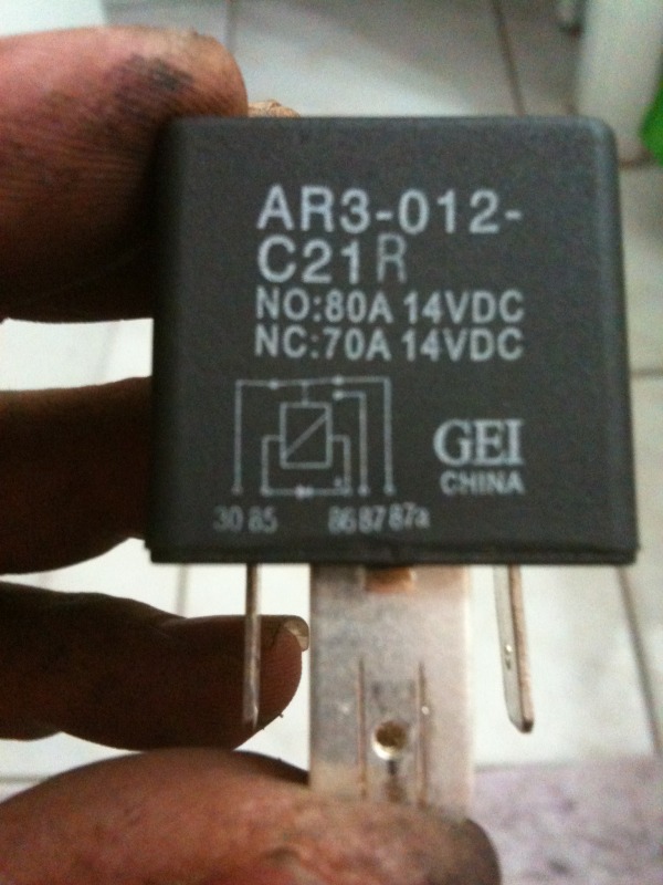
Ok, I used the diagnostic plug ( Blk/wht) but I could not get the relay to activate. If I use the 87a then it works, I know it (87a) works with the switch off. Now, if I use the old 30a relay it works fine? What gives with the 70/80a relay. I will try and post a pic of it. Thanks for all the help guys!!
05-11-12, 10:54 PM
#16
Jack you should give some thought to getting fan power from the main fuse link in the engine compartment. On my 1990 I had an unused fuse link. I cut the unused part of the harness and have a female spade terminal. In order to use the female spade I had to use my dremel to grind down the male spade. It's wider than the typical spade terminals you buy at the store.
Doing that allowed me to free up some clutter from my battery terminals.
Doing that allowed me to free up some clutter from my battery terminals.
I have never had a problem with my current (yes I intend the pun) set-up.
05-12-12, 08:55 AM
#17
Rotary Freak
Ok, I used the diagnostic plug ( Blk/wht) but I could not get the relay to activate. If I use the 87a then it works, I know it (87a) works with the switch off. Now, if I use the old 30a relay it works fine? What gives with the 70/80a relay. I will try and post a pic of it. Thanks for all the help guys!!
85 and 86 are the inputs to the coil of the relay to make it pull in. A permanent gnd to 85 and a switched voltage to 86 will pull the relay in. Then you have a batt source to 30 that will pass thru the relay when it pulls in and go to 87 which will feed whatever your wanting to power up.
If I misunderstood what you wrote......so be it, but that's the way stuff works.
There's other and bettter links on relays on the web but the one above is the (batt in the wireless keyboard went dead right here) first I came across.
This one is much better imho: http://www.the12volt.com/relays/relays.asp
 05-12-12, 12:37 PM
#20
Rotary Freak
06-01-12, 11:58 AM
#22
Senior Member
Thread Starter
Join Date: Jul 2005
Location: Orlando, FL
Posts: 566
Likes: 0
Received 0 Likes
on
0 Posts
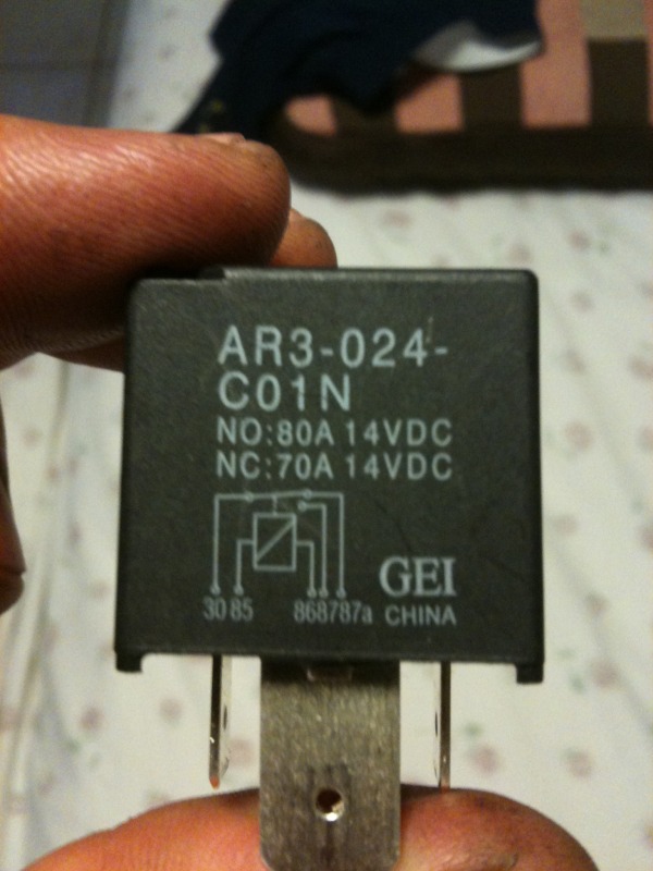
picked up a new relay and now nothing works? WTF!!!!!!!
I see that its a different part number and the schematic is def not the same. HAILERS2 need your help again.!!!!!!
I see that its a different part number and the schematic is def not the same. HAILERS2 need your help again.!!!!!!
 06-01-12, 03:37 PM
#25
There was an inductive shunt between 85/86, i.e. a diode. What it does (did) was prevent a reverse current when the coil's field collapsed. The new one doesn't have that. If it's not working now, make sure that it's
a) wired properly, as Hailers' drawing showed
b) it has power and ground to all the right places (use a multimeter or test light)
a) wired properly, as Hailers' drawing showed
b) it has power and ground to all the right places (use a multimeter or test light)