When you click on links to various merchants on this site and make a purchase, this can result in this site earning a commission. Affiliate programs and affiliations include, but are not limited to, the eBay Partner Network.
I have some questions that I am unable to find answers to.
The 20,000 mile switch. I know it is to aid break in, but since I will not have the Mazda connection to the ECU, what should I do with the wire that goes to the ECU? Should I leave it unconnected or hook it to ground or hook it somewhere else.
I have taken all of the rats nest smog plumbing out, where would you attach the atmospheric pressure sensor?
What about the over-the-top switch? I think it just powered a light or buzzer, so just leave it unattached?
Heater hoses. Which connection on the motor should go to the inlet side of the heater rad?
The 20,000 mile switch is irreverent. It is mainly an emissions related item which switches something in the ECU. ECU will happily run without it connected.
By atmospheric pressure sensor, are you referring to the sensor in the passenger kick panel or the boost/pressure sensor in the engine bay?
The boost/pressure sensor in the engine bay gets connected to a vacuum source after the throttle body.
The atmospheric pressure sensor needs to be connected to the harness. There is no other connection. It samples atmospheric pressure.
You do not need to care about the over the top switch.
I have done several of these transplants with the stock ECU and basically it is happy if the harness is stripped down to only AFM, injectors (with resistors if appropriate), TPS, CLT, IAT, boost/pressure, atmospheric, CAS, coils, knock sensor, knock box.
There are some differences between S4 and S5 though. Of course S5 needs the metering oil pump.
As for the heater hose, the connection on the rear iron is inlet to the heater core, the outlet of the heater core connects to the lower rad hose between the rad and water pump housing.
By atmospheric pressure sensor, are you referring to the sensor in the passenger kick panel or the boost/pressure sensor in the engine bay?
The boost/pressure sensor in the engine bay gets connected to a vacuum source after the throttle body.
The atmospheric pressure sensor needs to be connected to the harness. There is no other connection. It samples atmospheric pressure.
According to the diagrams I have been looking at, I am dealing with the Atmospheric pressure sensor. It has a 4 wire electric connection and a vacuum hose connection. The wires are connected to the ECU and the Vacuum hose is connected to the plenum chamber after the throttle body.
I have done several of these transplants with the stock ECU and basically it is happy if the harness is stripped down to only AFM, injectors (with resistors if appropriate), TPS, CLT, IAT, boost/pressure, atmospheric, CAS, coils, knock sensor, knock box.
Not sure what the CLT is, at least I'm sure it's NOT what it looks like. No wonder I could never find it.
The engine has the metering oil pump so I guess its the S5. The engine is N/A and unless I missed it, it came without a knock sensor. Is this possible or did I just lose it in the rebuild.
Thanks again for all your help.
The S5 OMP is fully electronic unlike the S4 which has a mechanical connection between pump and throttle body, but both series have an OMP.
S5's did not have a knock sensor.
According to the diagrams I have been looking at, I am dealing with the Atmospheric pressure sensor. It has a 4 wire electric connection and a vacuum hose connection. The wires are connected to the ECU and the Vacuum hose is connected to the plenum chamber after the throttle body.
Not sure what the CLT is, at least I'm sure it's NOT what it looks like. No wonder I could never find it.
The engine has the metering oil pump so I guess its the S5. The engine is N/A and unless I missed it, it came without a knock sensor. Is this possible or did I just lose it in the rebuild.
Thanks again for all your help.
You are referring to the boost/pressure sensor. The atmospheric sensor is normally located in the side of the passenger footwell, and samples the atmospheric pressure to allow for altitude compensation: air gets less dense at higher altitudes.
The CLT stands for coolant temperature: it is a green 2 pronged connector located directly on the back side of the water pump aluminum housing, below the thermostat. There is also a single pronged temperature sensor on the rear iron, below the oil filter pedestal and the oil pressure sending unit. This sensor is for the temperature gauge only and does not connect to the ECU.
The naturally aspirated models did not have knock sensors; only the turbo models did.
Hi Guys,
I've got more questions this time concerning the car interior heater.
I have 1 heater hose connected to the engine just below the oil filter mount and the other end to the heater input.
The other hose comes out of the heater and connects to the rad beside the lower rad hose.
Is that correct?
The reason I ask, is that there appears to be another place to connect a rad hose. If you have a Haynes Mazda RX-7 manual, page 163 (which is the only place that I've found a picture of what I'm talking about) it shows what looks like a rad hose connection.
I've added a picture to show what I'm talking about. The red pen points to the connection.
If that isn't a place to connect a rad hose what is it for?
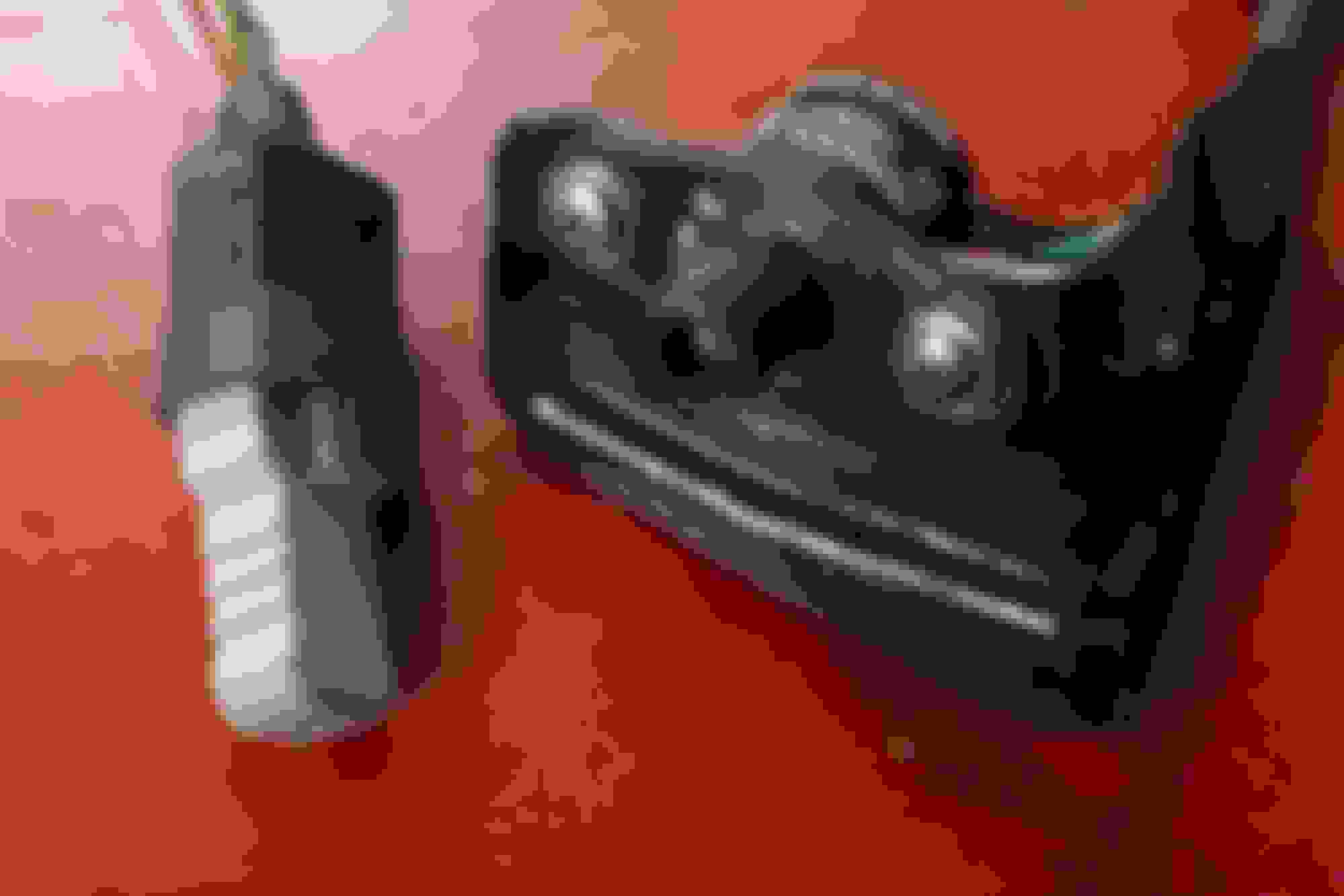
I've run into 2 more questions I need help with. The picture has 2 things in it. The left thing is wired into the fuel pump circuit, it may be an emergency off from the under hood position.
The other has a screw labeled R and L and is obviously for adjusting something under the hood.
As always, thank you for any help you can give me.
I've never seen the item on the left, but item on the right is the variable resistor. You can find info on it in the FSM, but as far as I'm aware you are just tuning idle mixture with it. My car has always had some sort of modified or standalone ECU, so that was one of the first parts to be thrown away.
You need the variable resistor. As mentioned, it adjusts the IDLE mixture.
What colour is the connector on the thing on the left? If it is yellow, then it is the fuel pump test connector which when jumped causes the fuel pump to run anytime the key is set to RUN.
Thanks Aaron,
Yep, yellow under the rubber protector. I thought it might be that.
And the variable resistor will get mounted on the left fender.
You guys rock!