
fuel pump resistor relay question (couldnt find it searching)

Thread Starter
Rotary Enthusiast
Joined: Aug 2002
Posts: 850
Likes: 0
From: MO
fuel pump resistor relay question (couldnt find it searching)
first of all.. will 9v turn on a standard 12v automotive relay or does it have to be 12v? second, the resistor has a wire running to it from the ECU to the relay part of it, when that wire is 12v does it open or close the resistor. in other words, is the wire from the ECU 12v at idle or at WOT??
Seduced by the DARK SIDE
Joined: Apr 2001
Posts: 7,323
Likes: 2
From: Orange Park FL (near Jax)
The circuit opening relay supplies 12v to the fuel pump resistor relay whenever the ignition is on & the engine is cranking or running.
The ECU supplies the ground (-) only when needed to pull up the relay & bypass the resistor.
The ECU supplies the ground (-) only when needed to pull up the relay & bypass the resistor.
I'm a boost creep...
Joined: Jan 2002
Posts: 15,608
Likes: 8
From: Auckland, New Zealand
Re: fuel pump resistor relay question (couldnt find it searching)
Originally posted by imloggedin
first of all.. will 9v turn on a standard 12v automotive relay or does it have to be 12v?
first of all.. will 9v turn on a standard 12v automotive relay or does it have to be 12v?
second, the resistor has a wire running to it from the ECU to the relay part of it, when that wire is 12v does it open or close the resistor. in other words, is the wire from the ECU 12v at idle or at WOT??
Thread Starter
Rotary Enthusiast
Joined: Aug 2002
Posts: 850
Likes: 0
From: MO
Re: Re: fuel pump resistor relay question (couldnt find it searching)
Originally posted by NZConvertible
Only the pump sees 9V, not the new relay. The relay is switched by the old fuel pump wiring, which after the rewire only ever sees the full 12V.
Only the pump sees 9V, not the new relay. The relay is switched by the old fuel pump wiring, which after the rewire only ever sees the full 12V.
Originally posted by NZConvertible
Have you looked at the wiring schematics? The normally closed relay is fed 12V from the Main Relay and the ECU switches it's ground, opening the contacts and making the resistor the only path.
Have you looked at the wiring schematics? The normally closed relay is fed 12V from the Main Relay and the ECU switches it's ground, opening the contacts and making the resistor the only path.
instead of getting "im gonna prove you wrong" replies from you NZ.. would someone else plz answer my question. when does the ECU make the ground.. at WOT or at IDLE? when does the resistor/relay-have 12v? is the resistor NOT resisting when its off.. and IS resisting when its on?
an answer to my question would be something like this: at WOT the green/red wire has __v running through it.. at idle the green/red wire has __v running through it.. and the resistor (not or is) making resistance when the relay is triggered.
i guess thats a better way to put it

Trending Topics
I'm a boost creep...
Joined: Jan 2002
Posts: 15,608
Likes: 8
From: Auckland, New Zealand
Re: Re: Re: fuel pump resistor relay question (couldnt find it searching)
I see you're still grumpy at me from the last pump rewire thread ... 
The relay is a normally closed one, meaning the contacts are closed until you put power to the coil. So the ECU does that when it wants to make the resistor the only path to the pump, which lowers its voltage.
The pump receives 12V when the engine cranks and starts, and for ~10 seconds after that. Then it switches to low voltage. It stays like that until the engine load increases beyond a certain point. From my testing this is at about 3psi boost, but it's more likely an airflow reading from the AFM that the ECU looks at, not boost.
Originally posted by imloggedin
when does the ECU make the ground.. at WOT or at IDLE? when does the resistor/relay-have 12v? is the resistor NOT resisting when its off.. and IS resisting when its on?
when does the ECU make the ground.. at WOT or at IDLE? when does the resistor/relay-have 12v? is the resistor NOT resisting when its off.. and IS resisting when its on?
The pump receives 12V when the engine cranks and starts, and for ~10 seconds after that. Then it switches to low voltage. It stays like that until the engine load increases beyond a certain point. From my testing this is at about 3psi boost, but it's more likely an airflow reading from the AFM that the ECU looks at, not boost.
Thread Starter
Rotary Enthusiast
Joined: Aug 2002
Posts: 850
Likes: 0
From: MO
thanks for not just trying to prove me wrong or somethin. im only soar because i cant get a straight answer out of anyone and my car wont idle for me to try it. with not alot of time to fix it, its not easy to get the answer
so from what i understand.. when the relay is triggered with 12v (via ecu ground) the resistor is adding resistance (dropping the voltage on the fuel pump). is this correct?
so from what i understand.. when the relay is triggered with 12v (via ecu ground) the resistor is adding resistance (dropping the voltage on the fuel pump). is this correct?
Seduced by the DARK SIDE
Joined: Apr 2001
Posts: 7,323
Likes: 2
From: Orange Park FL (near Jax)
Originally posted by imloggedin
so from what i understand.. when the relay is triggered with 12v (via ecu ground) the resistor is adding resistance (dropping the voltage on the fuel pump). is this correct?
so from what i understand.. when the relay is triggered with 12v (via ecu ground) the resistor is adding resistance (dropping the voltage on the fuel pump). is this correct?

HAILERS
Joined: May 2001
Posts: 20,563
Likes: 27
From: FORT WORTH, TEXAS,USA
Below is a paste job from an old post. I did a SEARCH and put in the words FUEL PUMP RELAY and HAILERS and came up with this old, old, old post. It should explain what 3D does in life:
I had a confrontation (???)with NZ about whether the afr would change at idle if the voltage at the pump, which is normally about 9 volts on my car, was instead the full 12volts.
So what I did, was fully warm the car up first. Then looked at the pumps voltage at idle and look at the wideband meters reading.
Then I depinned pin 3D, which removes a ground from the relay in the Fuel Pump Resistor Relay package, while the car was still idling.
I can assure you the afr got richer when the full 12 volts was applied to the pump vs when it only saw 9 volts.
Pin 3D on the ECU is what controls whether the pumps supply voltage sees the resistor or not. De-pinning means a full battery/alternator voltage and a pinned 3D means the resistor is in the circuit and the voltage drops to approx 9 volts.
Talking idle here. Nothing else.
Again, engine idling with pin 3D in the circuit and 3D out of the circuit. Engine kept running. No turning the engine off ....pull pin .....restart engine type thing.
Make sense? Note: I did this at least five times hoping it was a fluke. Not a fluke. I lost the bet.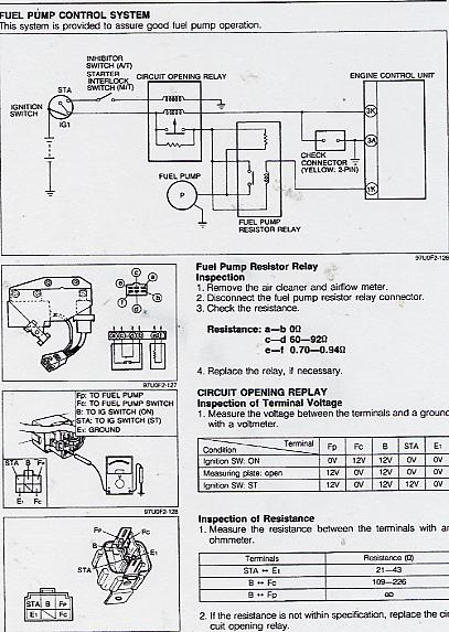
OOOPS. That's a series five fuel pump relay/resistor package. Works the same. 1K.....3D whichever. Just ignore it if you want. The image, I mean.
Last edited by HAILERS; May 7, 2004 at 09:36 AM.
Thread Starter
Rotary Enthusiast
Joined: Aug 2002
Posts: 850
Likes: 0
From: MO
so from what you just said HAILERS, when 12v is applied to the green/red wire it DOES make the resistor resist. and at idle it does have 12v on the green/red line. in other words.. at idle unplugging 3D upped the fuel pump voltage to 12v. is this all correct?
Thread Starter
Rotary Enthusiast
Joined: Aug 2002
Posts: 850
Likes: 0
From: MO
another quick question. with a 5 pin relay, does does current flow from 87a to 30 and then when 86 gets power it flips so power goes from 87 to 30. thats how im assuming it works.. i mean i know it works like that. but i read something that said somethin about current not flowing from 87a to 30 when the relay was off. is this true or not?
HAILERS
Joined: May 2001
Posts: 20,563
Likes: 27
From: FORT WORTH, TEXAS,USA
1. The GREEN/RED wire is a GROUND WIRE for the relay.
2. The relay has 12v on it anytime the key is to ON.
3. The GREEN/RED wire goes to pin 3D, where the ECU puts that ground on it and maintains that ground.
4. So now the relay has 12v on its coil and a good ground from 3D on the ECU. So the contact in the relay is pulled open and there is no continuity b/t the L wire and the LR wire on each side of that contact in the relay.
5. So the only path to the fuel pump is thru the resistor in the relay. That drops the voltage to the pump to 9v or so.
6. Wnen the ECU sees boost/load thru the afm (or whatever triggers it), then the ECU removes the ground on the green/red wire and the relay relaxes in the assy, and now there is a path thru the contact in the assy and the voltage to the pump rises to ....whatever the alternator is putting out that day.
Last edited by HAILERS; May 7, 2004 at 04:38 PM.
I'm a boost creep...
Joined: Jan 2002
Posts: 15,608
Likes: 8
From: Auckland, New Zealand
imloggedin, are you reading the FSM? All the info you need is there.
System schematic, page 4B-72
Resistor/relay test, page 4B-73
Wiring diagram, page 50-34
For your relay question, read this.
http://www.autoshop101.com/forms/hweb2.pdf
System schematic, page 4B-72
Resistor/relay test, page 4B-73
Wiring diagram, page 50-34
For your relay question, read this.
http://www.autoshop101.com/forms/hweb2.pdf

Thread
Thread Starter
Forum
Replies
Last Post
trickster
2nd Generation Specific (1986-1992)
25
Jul 1, 2023 04:40 PM
alphawolff
1st Generation Specific (1979-1985)
17
Nov 17, 2015 05:57 PM