When you click on links to various merchants on this site and make a purchase, this can result in this site earning a commission. Affiliate programs and affiliations include, but are not limited to, the eBay Partner Network.
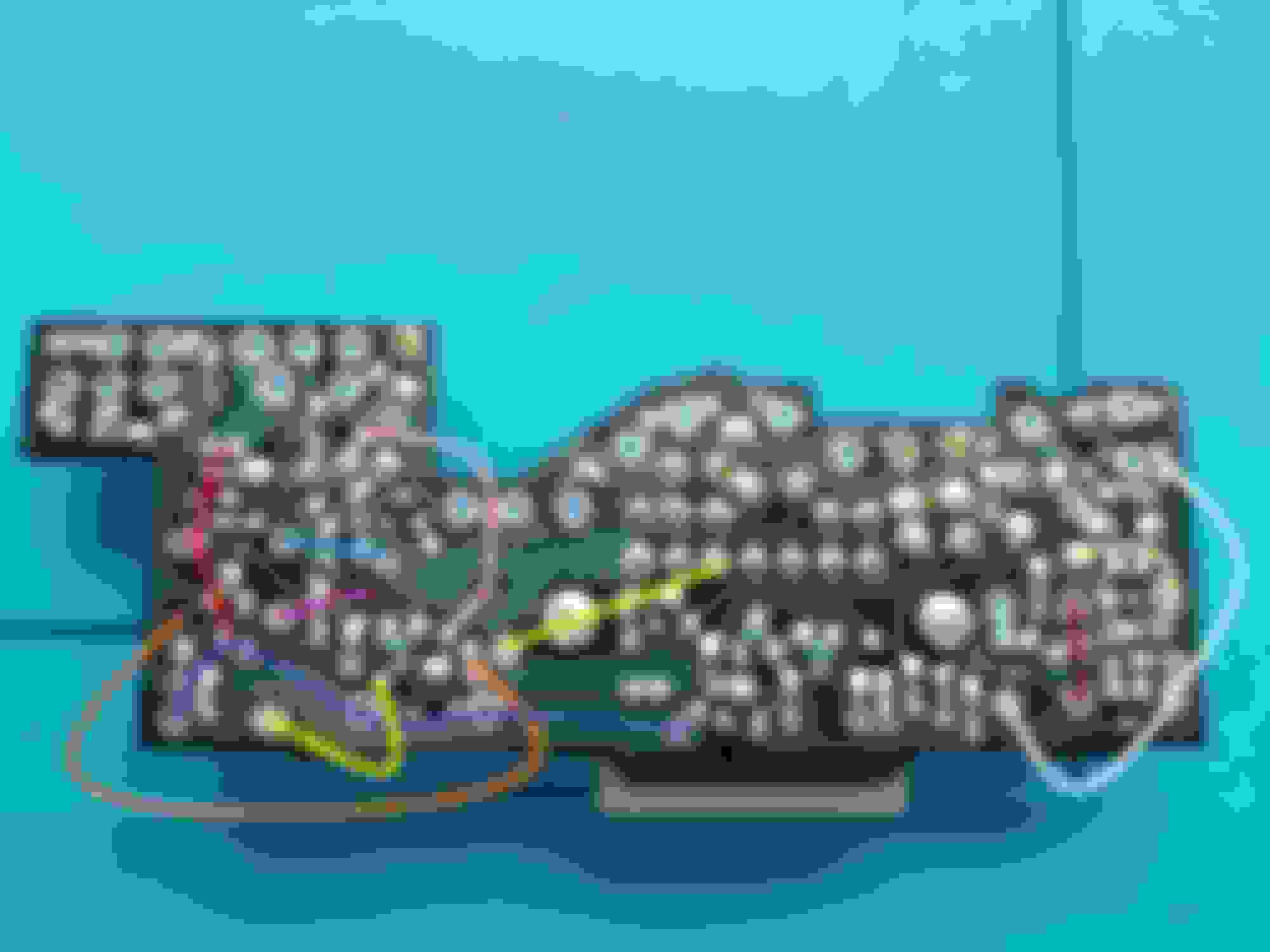
I recently replaced the relays in my dead wiper switch and i ripped out several PCB pads. After searching high and low the only image I found with jumper connections was very small, hard to see, and didn't include all of the pins. I'm posting this up to hopefully help someone out with wiper switch troubles related to relay pad connections. I have went through the trouble to provide these diagrams of where each pin should be connected. A simple continuity test with DMM will confirm if you need to add a jumper wire or not. I also have posted some of the other blind pads and where they connect from the relay side. I plan on posting other pictures for the individual switch pins (Rotary wiper switch, spray switch, rear wiper switch, hazard switch) As I had issues with the variable resistor and really wished I had a pin out for it. Hopefully this will help someone out with diagnostics too.
I'm happy to confirm that with these connections to the relays your wipers should be fully functional.
Enjoy
I have never met with such a problem, but am happy that if I would I am sure that I will be able to do anything right together with your help, thanks for the explanation of everything and for the photo which you had add. Always when I had problems with the pcb chip I simply went and bought a new one but now I will try to repair it by myself because I see that you have succeeded and now I understood that small problems I can solve by myself. Again thank you very much.
Last edited by fionamabe; Dec 12, 2020 at 04:11 AM.