When you click on links to various merchants on this site and make a purchase, this can result in this site earning a commission. Affiliate programs and affiliations include, but are not limited to, the eBay Partner Network.
Hello everyone, my wiper switch (probably) has been acting up for a while now: The park function did not work about 95% of times. I did some measuring and found that the usual suspect, the bottom relay did not properly return to its normally-closed state. Replaced the relay, which in turn did not fix the issue, that is, until I disconnected and reconnected the switch. Not wanting to anger the God of Electronics in the car I left it there, hoping it would stay working, which of course it did not. I did some more measuring of the board and made the following observations:
- The middle relay controls LOW speed, and does so correctly as far as I can tell. This operates using the L input, which goes through the switch and activates the relay (which then connects L/W, the wiper low-speed cable, to ground).
- The bottom relay controls HIGH speed and MIST, and does so correctly. This operates using L again, which goes through the switch and activates the relay (which then connects L/R, wiper high-speed cable, to ground).
- The bottom relay passes through L/Y (wiper motor position switch) to some circuits after it. This is normally closed and the resistance from input connector to after the relay is 0 ohms.
- When in operation, the wiper motor switch provides 11.9 volts to the switch board, when the wipers are parked (or at least close to the bottom). This passes through the relay properly. If the wipers are not parked, the switch provides 0 volts.
- All four pass-through sleeves are undamaged and working perfectly.
I made the following assumptions of the system based on this:
- INT is controlled by some transistor-based circuit that momentarily activates the middle relay (then Park takes over).
- Park is controlled by some transistor-based circuit that activates the middle relay.
- Bottom relay controls the high speed, and disables the park function while the wiper is in high speed (to avoid putting both low and high speed on at the same time I assume).
- Problem is in the park circuit (?).
I could not make further measurements of the exacts of where the wiper switch actuates as I managed to accidentally short L to ground, which burned up a part of the trace. I should also mention that I re-soldered everything accessible and it did not change anything. My current plans are to disassemble the switch so I can look at the other side for damaged components, but the lack of a schematic makes this a lot harder than it should be, so before I get there I would like to ask everyone if you have any ideas, or if what I deduced is correct. One thing that caught my attention is that I expected the park switch to provide 12 volts when NOT parked, contrary to what I can see here.
Unfortunately no, I verified pretty much all of that. The relays really seem to be just fine (and, well, its also brand new). Also, some information circulating around this board regarding the exact job of each relay seems incorrect, for example:
The larger relay controls the High/Low speed selection.
I'm fairly confident in my measurements and that relay only controls LOW.
My "easiest" question here is regarding the correct behavior of the position switch in the motor: When should it be closed and open?
Otherwise I'm kinda clueless here, the switch seems rather hard to disassemble too so I'm not looking forward to that one.
I had an old wiper switch that I disassembled. This switch is from US-spec S5 coupe with rear wiper. The PCB (non-foil side) is populated with discrete ECAPs (7), resistors (2), diodes (2) and the 3 relays. (Photo is attached.) The foil side of the PCB is populated with SMD 3-terminal devices (~10), which appear to be either transistors and/or voltage regulators, and SMD resistors (~20). It's hard to pinpoint what might be causing your problem. The ECAPs typically have a limited lifespan and may have leaked, which may be contributing to your problem. I have another old wiper switch that I'm planning on rebuilding by replacing the relays and ECAPs. I would suggest that you start by first replacing the simple components (i.e., relays and ECAPs) that are most likely to fail, and if that doesn't solve your problem start checking the other susceptible components.
I'm not familiar with the internal workings of the wiper motor, but I believe there are contacts actuated by a cam inside the motor that act as a park switch. I'm still using my original wiper motor that's now 30 years old. Haven't had any problems with it. Good luck.
You need to be careful during the de-soldering process. Especially when de-soldering the board from the switch. Everything is close quarters when in the switch. I used soldering wick and an adjustable heat Weller soldering iron to keep the temperature down. From previous posts, some folks had problems with burnt traces due to using a too high temperature soldering iron. If you're handy with a soldering iron, than you shouldn't really have any problems.
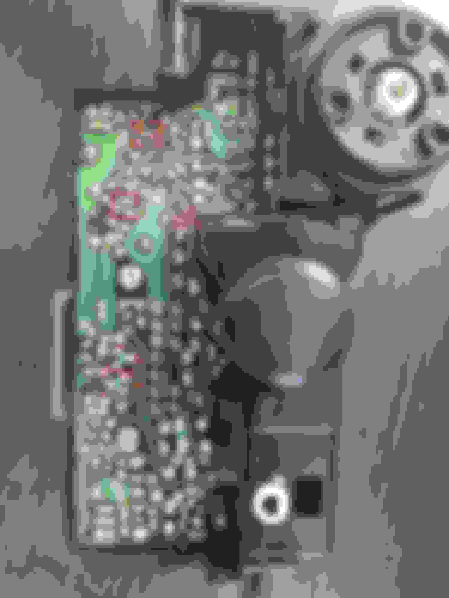
I made some progress: There is not much (relevant to the front wiper) on the other side of the board, only one diode and two ECAPs. The diode connects L (12V) to the rear-wiper portion of the board, while the two ECAPs connect L with the INT / Park circuit. However I found some weird behavior on the transistors of the board. All black SMD transistors behave like standard NPN transistors when checked with the multimeter (as two diodes). The green SMD transistors (?) exhibit a different behavior:
- 3 and 4 behave like an NPN
- 2 and 5 act as a diode between A and B, but A -> C is a broken circuit.
- I also marked the shorting mishap as 1
I find this rather weird. I would expect all green transistors to act in the same way. To complicate things, the rear and front INT/Park circuits are practically the same (except the front has a variable resistor to control interval, while the rear is fixed at about halfway), and the respective transistors behave in the same way. This seems to be a big coincidence, so either those four are not transistors and and/or are not the same type of components, or I really have the same failure with two silicon transistors which seems rather unlikely. (Unfortunately I don't know if the rear wipers work correctly, as they don't properly fit under the louvre and were never used and I didn't repair the burned away trace yet for further testing.)
I have a favor to ask: I would really appreciate it if you (or anyone) could measure the green transistors to confirm their behavior.
Apart of this I did not find anything noteworthy yet, ECAPs and the SMD caps behave like capacitors (I can't measure capacitance, but they don't appear to be seriously degraded), other transistors, traces seem to be fine, the switch also seems to function normally.
Last edited by Barnahadnagy; Feb 16, 2020 at 08:51 AM.
Yes, sorry if I was not clear, thats the part I broke by shorting it to ground accidentally. It is not the failure I'm looking for (it however disabled all functionality of the switch), I just did not have time to jump it yet.
I checked transistors 2, 3, 4 and 5 on PCB. The pinout configuration for a SMD transistor (https://www.el-component.com/bipolar...istors/mmbta55) is B (bottom left), E (bottom right) and C (top). On my PCB, all these transistors (2, 3, 4 and 5) checkout to be PNP transistors. I get voltage drop of about 0.65V between B(-) and E(+), and B(-) and C(+), which indicates a PNP transistor. Reversing the DMM leads gives 0V for same transistor configuration.
I read something about 3 wires into the motor and one black that's supposed to be grounded, it may not be grounded and causing the non parking issues. Should have power between blue and black.
I'm also running into this parking issue and might explore this idea.
I've been busy with progressing with the board, I did measure the motor switch behavior. I think the best way to do it is to first move the wiper then disconnect the battery and then measure the resistance at the switch connector (assuming you have it disassembled anyways). FSM page 50-44 (Front wiper wiring diagram) has the connector pinout as figure CR-01.
- You can move the wiper by shorting L/W (Wiper motor lows speed) and B (Ground). (Or reconnecting the switch)
- When the wiper is parked and battery is disconnected measure resistance between L and L/Y: It should read 0 (or few) ohms, while L/Y to B should be infinite or at least very high.
- When the wiper is not parked, it should be the other way around, L/Y to B should be close to 0 ohms.
You can also measure all this at the motor, but I already had the switch out so it was a lot more convenient to do it in the cabin. Just be sure to always disconnect the battery before measuring resistance as actually having voltage between the cables would likely damage your multimeter.
It has been a while, but I finally got around fixing it. All transistors and, surprisingly, even the capacitors checked out to be fine. I'm not 100% sure what the problem was, my best guess is the soldering on one of the capacitors on the back of the board.
So far in my experience pretty much all electrical issues are caused by bad soldering or dirty contacts on this car.
Part number for small relay should be G6C-2114P-US-DC12 (the board takes two if you got rear wipers, usually the front wiper one is the bad one. Front has two relays next to eachother, rear has one alone by itself), the bigger one can be replaced by G5LE-14-DC12, both Omron. I ordered from Mouser EU, but you should be able to find them more locally by part number.
Absolute legend thankyou.
I ended up coincidentally coming across the G6C-2114P about 5 minutes after my post one on a random google but couldnt find anything about the park relay
The 5-legged specimen fails less often I suppose. Worked fine for me too but might as well replace it since its already disassembled. If you feel confident with the soldering iron you might want to re-solder the connectors or all the board as well (works for all the electrical issues ).
Hi barna,
Do you have any knowledge regarding the headlight cluster?
I got a the old "every single light works on my car but the headlights won't pop up without activating the washer switch" trick.
I've gone through and checked both the headlight and flasher relays mounted down on the front bar and they're both good.
Next I went searching for earths and all seems good there also, however I can't find the earth that should be mounted near the coils behind the LH wheel arch? It's been moved somewhere....
next I moved onto the PCB in the headlight cluster and had it striped out cleaned up and re-soldered back together (no parts replaced or checked other then visually) and also the smaller light dial PCB wasn't removed or cleaned because I figured it's still working.
Next i removed the front bar and intercooler and striped the wiring bare from the pop up motors until I came across where the earth for the headlights, fog lights and pop ups all connect together. Everything was all good there also.
So in short would i be right to assume im now im trying to find the missing number 5 earth which has been moved somewhere or looking for a potential busted relay, diode or something in the cluster itself.
Anyones advice is welcome.
Thanks matt
it also has a halteck platinum sport 1000 ecu in it if that has anything to do with the missing number 5 earth?
I'm not at all familiar with the light switch. So they pop up when you press the washer switch? Just looked at the wiring diagram and that does not seem like something that has any right to work
They don't work with the manual pop-up switch either? If you have the switch out, I would measure resistance between R (input power) and R/Y and R/L (R-R/Y should be 0 with manual mode down, R-R/L 0 with it up). If the manual switch is up and you press the washer you should get 0 between R and L/O. See wiring diagram page 50-51 for the connector layout. If this works I think you can rule the switch out.
Yeah its night time here so i had to put the tools down but my scenario is that the pop ups will pop up with the washer switch yes. But they will not pop up with the head light switch. All lights work including highbeam.
I have been checking out the scematics also to see what i need to touch to check for continuity it the cluster itself. I just thought I'd ask the question to see if anyone had replaced any diodes electrodes or relays on the cluster for the modern part numbers. Or for any other advice on what to check because I've been combing through the threads for 4 days now and I feel as though I've checked everything in them.
The connections I mentioned are my best bet without any actual experience. There is a relay in the switch but if you use the manual pop-up (not the one that also turns the light on) the relay is partially bypassed. And the washer switch thing just looks really weird, unless I'm missing something either the diagram is wrong or something is wired wrongly.
Its probably a dumb question but im only learning to read these wiring diagrams since 5 days ago..
When the headlights are turned on shouldn't the power supply be coming from R/W or W/G instead of R?
Isn't R the power supply from the washer/ manual up switch?
Feel free to shoot me down lol 😆
R/W is the ground for the headlight light relay, so when you move the switch to the headlight position it connects to ground, activating the relay. The same switch also grounds the headlight motor relay that is in the switch. R supplies power to the headlight motor relay, the manual headlight motor switch (thats the one on the very left) and through either one of the previous switches, to the washer motor. Note that the motors themselves have individual relays up front too, those are controlled by either the motor relay or the manual switch. W/G supplies power to the parking lights (through another switch that is connected to the main ****) and the interior illumination (through a variable resistor in the dimming ****).
Wiper doesn't go to park. Pulled switch and fully checked it. Couldn't find anything but a burnt transistor. Also replaced the capacitors. Both without succes.
We took a transistor of from the rear wiper circuit, couldn't find what kind of transistor it is.


 ).
).


