
was this a factory ground at one point?

Thread Starter
Joined: Jun 2010
Posts: 519
Likes: 1
From: Carson City, NV
So i was poking around trying to see the "ecu Ground" on my block underneath my uim to try and fix my 3800 hesitation issue and noticed this.
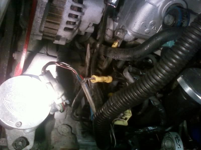
Doesnt look factory to me, was there a factory ground there at one point? it looks like the insulation from the dizzy wiring or whatever was used as a ground..
Doesnt look factory to me, was there a factory ground there at one point? it looks like the insulation from the dizzy wiring or whatever was used as a ground..
talking head
Joined: Apr 2008
Posts: 2,775
Likes: 15
From: Perth, WA, OZ
someone has joined the shield for the cas wiring to an earth point
seems to me they may have been chasing the hesitation issue
this is actually the wrong thing to do,,, for it should already ( correctly ) earthed at the far end and so work as a farady cage to collect RFI and feed it an easy path to ground
having it earthed at both ends somewhat kills the intended cage effect
and may instead force the CAS wiring to work as a conduit to balance earth potential between block and ground
this may infact introduce noise to the CAS signal wiring
under the UIM on turbos you should have a very decent earth wire bolted to top of the housing at the mounting point for the top mount brackets
the real fix for the usual staging issue is in repairing the crimped joins that bundle all the earth wires and shield together
,,, not far out from the ecu
cut that silly join from the CAS wiring and if you have hesitation issues on staging then instead repair the loom here-
it is a known good reason for all the trouble,, and am guessing the earth to the block and various locations have been altered or displaced
its also very easy ( and nearly free ! ) to fix and cross off the list
please ignore the obviously radical departure from some of your wiring colour schemes
i think this was a N327 NA aussie wiring loom
blacks and black /grey dash are earths
the orange /black is a power ( B/Y on US ) , do not solder an earth here, but resolder the crimp

peel the tape back a bit from the cu end of the plugs
look for the black /grey dash or other FC earth colour wire bundles
and also for where the shield for the lambda etc tie in

its not all that far in but you have to untape the square loom gatherers


the orange shown here will likely be black with yellow or other FC power colour
dont earth it,, but resolder the crimp,, this one is also a likely culprit for volt changes when staging


bottom pics shows its not all that far in
overall there is two earth bundles/ tie ins which you resolder and add a decent fresh earth back to the ecu from
there is also the power crimp which is neglected , so look out for it when in there
Thread Starter
Joined: Jun 2010
Posts: 519
Likes: 1
From: Carson City, NV
i dont fully understand your write up, all the wiring repairs are being done very close to where it plugs into the ecu correct? theres a power wire bundle on my car black with yellow stripe correct? just resoldier that joint and re-tape/heat shrink it? then do the same on my grounds (all black wires on american cars still correct?) and at the end of your thread its saying to add another wire and make a new ground for it?
sorry for the million questions, i just want to measure twice and cut once!
sorry for the million questions, i just want to measure twice and cut once!
Basically, cut that yellow connector off and remove the black wire where ever it is attached. It is not a factory ground. It is a very very bad idea whomever did that. After that continue your search for the stock factory grounds, and clean those up.

Rotary Freak
Joined: Jul 2008
Posts: 1,660
Likes: 2
From: FORT WORTH TEXAS
The grounds are shown in the two attached jpg below.
If you follow any of those ground wires from the ECU plugs up the harness (unwrap the tape around the harness like BUMPSTART says), you'll find three of those wires all spliced together with a mechanical crimp device. '
Add a new gnd wire to that mechanical crimp and also solder all them together at the same time. Then put a ring terminal on your NEW wire and terminate that new ring terminal at a known ground point. Like I used one of the studs that hold the ECU bracket to the chassis and that worked fine.
The wire out of 2D is the 02 sensors input to the ECU. That wire is the center conductor of a shielded cable. As you follow that black wire at 2D up the harness it will enter a GREY shielded cable. The SHIELD of that cable is also spliced to the ground wires of 3A, 3G, 2R. Make sure you don't actually ground the black center conductor coming off 2D to ground. Not good thing to do. Be careful.
Now take a look at my second jpg I attached. You'll see all those gnd wires off 3a, 3g, 2R all spliced together. See that???? The dotted line next to 2D represents the shield wire of the shielded cable for the 02 sensor. Take note.
NOW look where I drew lines in GREEN. Those green lines are the ground wires for the various sensors in the engine bay. So what this means is, that when you add a gnd to 3a, 3g, 2r, your also adding a gnd to the gnd wires for the sensors in the engine bay and also to pin 2C of the ECU which is the end point for those sensor grounds just mentioed. Just FYI.
At the very bottom of the second jpg page you'll see ground point 24. The number is very blurred in this jpg. That gnd point 24 is on top of the Rear ROTOR housing and is terminated with a ring terminal with two black wires if memory serves. Usually the problem is not that ground point but the problem lies with the mechanical crimps used inside the EM harness. That's why your adding a extra gnd wire to the three gee, two rrrrrr, three aaaaa about a foot up the plug harness from the ECU.
Thread Starter
Joined: Jun 2010
Posts: 519
Likes: 1
From: Carson City, NV
Aside from having some ugly soldering skills, i THINK my hesitation issue is gone. i want to drive on it more before i say it is for sure because the problem never seemed to be consistant.
Thank you for your help!
Thank you for your help!
Trending Topics

Thread
Thread Starter
Forum
Replies
Last Post
rgordon1979
3rd Generation Specific (1993-2002)
40
Mar 15, 2022 12:04 PM
Jeff20B
1st Generation Specific (1979-1985)
73
Sep 16, 2018 07:16 PM
acha3
2nd Generation Specific (1986-1992)
7
Sep 6, 2015 08:14 AM