Error code 12 and 18 with brand new TPS

like the title says
this all started when my tps would not set to 1k ohms, it was at a steady 3.6k ohms. (this was a mysterious tps i bought on rx7club) so assuming the sensor was bad i bought a brand new one.
Just installed that today and warmed my car up and hooked up a DMM to set the ohms, it read 3.6k odms.... so i checked my palm pilot, (for the rtek 2.1) and i still have code 12 and 18 ( Narrow band and wide band TPS).
i dont really know what to do, could something be wrong with the throttlebody thats keeping the tps plunger depressed so its reading 3.6k ohms. also im VERY confused as to why i have error code 12 and 18 still. any help would be greatly appreciated.

yes im pretty sure the thermowax is hooked up (its on the firewall side of the TB right?) it idles at like 1300 and the idle is slightly inconsistant. yes the car was fully warmed up.
about the thermowax, my car does tend to die when i first try to start it, once warmed up it holds its own though. could this be a sign of thermowax problems?
about the thermowax, my car does tend to die when i first try to start it, once warmed up it holds its own though. could this be a sign of thermowax problems?
Trending Topics
In your previous post you stated " but that still doesnt explain why the ecu thinks the tps isnt even plugged in," which implies that the ECU belives the sensor is not plugged in and I'm saying it can be plugged in but still throw a code. As to the exact cause is yet to be determined. Just use the correct two wires to measure the ohms if you must set it that way. The much easier way is to set the G/R wire to 1 volt w/the key to on and the engine as hot as it can get. This same wire should have the 1 volt reading at the ECU as well.
What did you use as the ground source for the multimeter. If it was a sufficient source then you need to check the ECU grounds. You can measure the ground wire, Brown/Black, for this sensor w/key to on and it should read 0 volts or very close to it.
Last edited by satch; Jun 18, 2013 at 11:51 PM.
Joined: Dec 2001
Posts: 10,630
Likes: 3
From: NY, MA, MI, OR, TX, and now LA or AZ!
my tps has no brown and black wire...
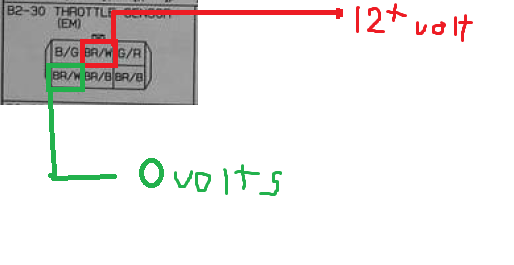
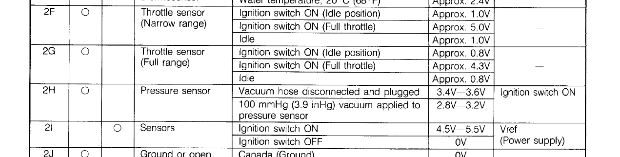
Did you do something incorrect here, or did you seriously read 12 volts at the TPS? Nothing at all should be reading 12V at the TPS. The ECU only sends a 5V signal to the thing! As you can see from the diagrams, that G/R wire is supposed to be the narrow range. It should read ~1V at throttle closed, and ~5V at roughly over about 30% throttle. Check the voltage on the BR/W wire. If this is really 12V+ you have a serious issue and need to find out what is bleeding voltage into the sensor feed. That high of voltage can damage something.
my tps doesnt have a black/white wire, but the harness that it hooks to does. is that what you are talking about? the black/white wire thats on the main harness and plugs into the tps?
Joined: Dec 2001
Posts: 10,630
Likes: 3
From: NY, MA, MI, OR, TX, and now LA or AZ!
Yes, the wires in the diagram refer to the harness -> connector, and not the wires on the TPS itself. It's best to stick with the diagram colors for diagnostics. In any event, none of the wires should ever see 12V.
Check the BR/W wires (going off the harness side colors), each should only be at 5V (VRef). If it's 12V, you found your problem.
Check the BR/W wires (going off the harness side colors), each should only be at 5V (VRef). If it's 12V, you found your problem.
Joined: Dec 2001
Posts: 10,630
Likes: 3
From: NY, MA, MI, OR, TX, and now LA or AZ!
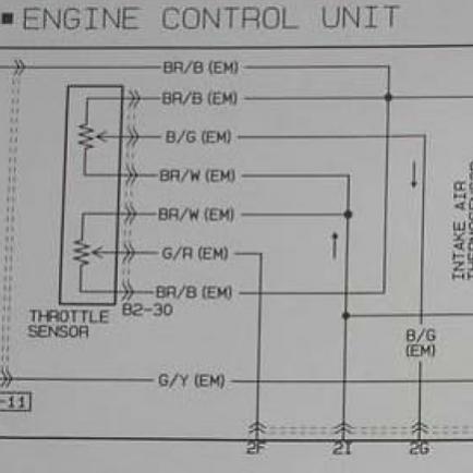
N/A to TII shouldn't matter. Let's avoid the confusion by using this:
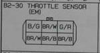
You can see where each wire should be in the connector now, so this should avoid color problems. Just locate the corresponding pins on your connector and test them.
To test:
Disconnect your TPS, stick one probe in either BR/B pin slot, then the other into either BR/W slot. You should see no more than 5V doing this. If you can't get anything, ground one end on the block/battery, and probe the BR/W pins. If you're getting 5V on both of those wires, the ECU VREF should be alright. Then you can plug the TPS back in, and backprobe the G/R and B/G wires to check the TPS voltage.
when i tried testing the BR/W pin with the BR/B pin i got 0 volts, couldnt get a reading, so i hooked up one of the DMM tester probe to battery terminal and tested the 2 BR/W pins with the other probe.
maybe this is where the volt leakage is happening one of the BR/W pins is getting no power..?
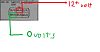
maybe this is where the volt leakage is happening one of the BR/W pins is getting no power..?