
88 rx7 wiring diagram


Thread Starter
Full Member
Joined: Nov 2004
Posts: 89
Likes: 0
From: North Philly
88 rx7 wiring diagram
ok i need a diagram of the harness specifically were the engine harness(by ecu) spits off under the dash....am swaping a rotary into another car(miata if u must know lol) and i need to connect the dash harness with the engine harness to make everything work, or at least i need to know what wires power the ecu so i can get the thing started...thanks much appreciated


Ill post both anyway in case somebody else needs it.
Non Turbo S4 ECU
TURBO S4 ECU
OR
you can just download the FSM here
http://www.rotaryheads.com/PDF/2nd_gen/
Non Turbo S4 ECU
TURBO S4 ECU
OR
you can just download the FSM here
http://www.rotaryheads.com/PDF/2nd_gen/

Full Member
Joined: May 2010
Posts: 46
Likes: 0
I know this is an older thread but I thought it might be useful...
Those schematics are very helpful to me as well, thanks for posting them. Is there anywhere that will tell me what wires on the harness side will correspond to these pins?
See my RX-7 is electric and I'm trying to remove the ECU. All I need to work at this point is the AC/blower, so I think all I have to do is to bypass the ECU with some 12v current to the right pin, but I need to know where that pin actually connects on the connector side rather than the ECU.
If anybody has that info I'd appreciate it! Thank you!
Trending Topics

Rotary Freak
Joined: Jul 2008
Posts: 1,660
Likes: 2
From: FORT WORTH TEXAS
The free online wiring diagrams, at this forums FAQ thread , show what wire goes to which pin on each and every plug on the car. You have to download the diagrams and actually look at them.
ECU has little to no effect on the blower motor. The Logicon does most all the work. The wiring for the Logicon and heater/ac are shown in the online and free wiring diagrams plus also shown to some extent in the free online factory manuals.
Look in the FAQ
ECU has little to no effect on the blower motor. The Logicon does most all the work. The wiring for the Logicon and heater/ac are shown in the online and free wiring diagrams plus also shown to some extent in the free online factory manuals.
Look in the FAQ

Yo, HAILERS2
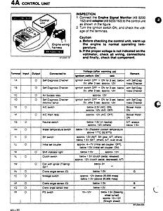
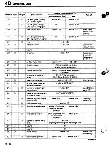
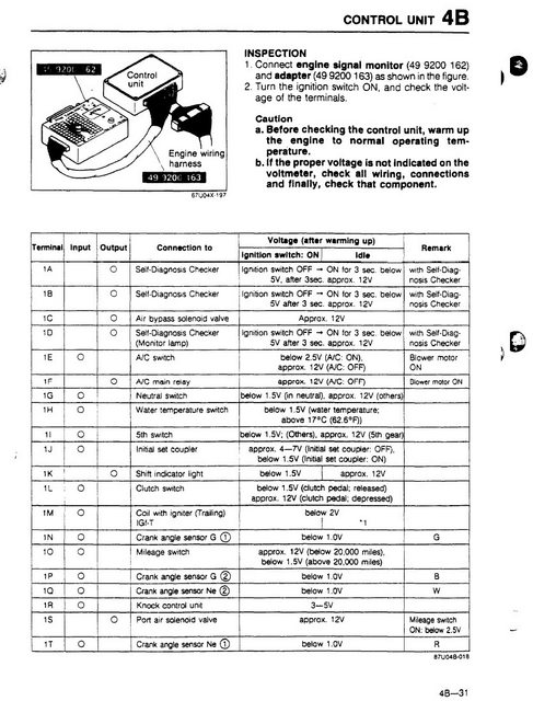
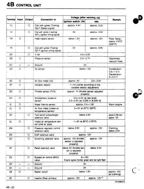
I am trying to help someone on the technical newb board and he is having the following problem. Pin 2I, Water Thermosensor, is showing 10 to 11 volts w/key to on and zero volts w/the plug pulled off of the sensor and key still to on. His Vref voltage is 5 volts w/key to on and a couple of the ECU grounds show zero volts w/key to on. What do you think in the tarnations is going on here? He has yet to do an ohm reading on the G/W wire at pin 2I nor jiggle the harness that connects to the sensor to see if it changes the voltage reading.
https://www.rx7club.com/new-member-rx-7-technical-256/eng-inj-fuse-repeatedly-blowing-rx7-984403/page3/
Full Member
Joined: May 2010
Posts: 46
Likes: 0
The free online wiring diagrams, at this forums FAQ thread , show what wire goes to which pin on each and every plug on the car. You have to download the diagrams and actually look at them.
ECU has little to no effect on the blower motor. The Logicon does most all the work. The wiring for the Logicon and heater/ac are shown in the online and free wiring diagrams plus also shown to some extent in the free online factory manuals.
Look in the FAQ
ECU has little to no effect on the blower motor. The Logicon does most all the work. The wiring for the Logicon and heater/ac are shown in the online and free wiring diagrams plus also shown to some extent in the free online factory manuals.
Look in the FAQ
The reason I posted on this thread is because I saw in the ECU diagrams that there is an output which says it will turn the blower on, so it does seem to play some part unless I am mistaken.
Lastly, there is no such thing called the "logicon" in the parts listing in the wiring diagrams anyway, so even if I could read it, how am I supposed to find anything?
I'm looking for more specific help here if anyone is so inclined, and if I need to start another thread that's fine.
I know this is an older thread but I thought it might be useful...
Those schematics are very helpful to me as well, thanks for posting them. Is there anywhere that will tell me what wires on the harness side will correspond to these pins?
See my RX-7 is electric and I'm trying to remove the ECU. All I need to work at this point is the AC/blower, so I think all I have to do is to bypass the ECU with some 12v current to the right pin, but I need to know where that pin actually connects on the connector side rather than the ECU.
If anybody has that info I'd appreciate it! Thank you!
Those schematics are very helpful to me as well, thanks for posting them. Is there anywhere that will tell me what wires on the harness side will correspond to these pins?
See my RX-7 is electric and I'm trying to remove the ECU. All I need to work at this point is the AC/blower, so I think all I have to do is to bypass the ECU with some 12v current to the right pin, but I need to know where that pin actually connects on the connector side rather than the ECU.
If anybody has that info I'd appreciate it! Thank you!
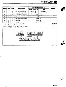
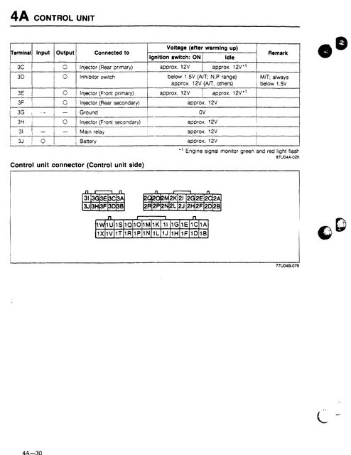
1F is Blue/White, 1E is Blue/orange
Full Member
Joined: May 2010
Posts: 46
Likes: 0
BTW, I'm starting to understand the wiring diagrams more, but a lot about them is still quite confusing...
Rotary Freak
Joined: Jul 2008
Posts: 1,660
Likes: 2
From: FORT WORTH TEXAS
I was lucky to get out of grade skool so I'm average/normal as the next person.
The ECU just puts a gnd on a Air Conditioning Relays coil when the a/c is selected and this coil in turn pulls in and supplys power to the a/c compressors magnetic clutch so the compressor will now start .............compressing freon/whatever is in there.
Blower motor and or how it gets power..............................I outlined the Logicon in RED in the attached jpg to show it exists.
Power for the blower motor comes off the line I colored GREEN in the jpg. It starts at the top of my jpg.........goes to a set of contacts in the HEATER RELAY.
IF the heater relay gets a ground signal from the LOGICON on the left of my jpg (G/R colored wire) then the heater relay pulls in and now power passes thru that heater relay.
So power leaves the heater relay and now travels on to the right of the jpg I attached. IF the slider on the LOGICON is FAR RIGHT POSITION, then the EX-HI relay pulls in and the power goes directly to the BLOWER MOTOR. and that sucker spins up and blows.
IF the slider on the LOGICON is not in the far right position, the power does not pass thru the EX HI relay but keeps traveling to the right of my attached jpg. It now goes down to the BLOWER RESISTOR and passes thru said resistor if that sucker isn't screwed up...............and now power goes upwards in my jpg (green line) and goes to the BLOWER MOTOR to spin that sucker up.
So with my green line I just explained how there are two ways for power to get to the blower motor. One way is thru the EX HI relays contacts and the other way is thru the BLOWER RESISTOR.
The LOGICON is important because it supplies the gnd to the two relays that make things work. The two relays are......EX HI relay and HEATER RELAY. shown in the jpg attached.
Bad LOGICON not outputting a gnd to those two relays can cause problems and of course lack of power to those two relays causes major problems.
I left out any talk about the ECUs ground input to the refrigerant pressure switch..........cause the ECU has not much of anything to do with the blower motor working at all.
NOTE; MY green line in the jpg also takes a upwards turn to the Air Conditoning Main Relay but ignore that 'cause the a/c main relay has zip to do with the blower motor turning on/off or sideways. ECU has little to do with the blower motor working. In fact nothing to do with it at all.
The LOGICON and those two relays I mentioned and shown in my jpg make the blower motor work.
Well.............I did leave out the transistor and the L/O wire from the LOGICON but it matters not too much although it does matter. The transistor that is.
LOGICON has three gnd signals it sends to that blower motor circuitry. The L/O wire, the L/Y wire and the G/R wire. So Logicons matter.
Rotary Freak
Joined: Jul 2008
Posts: 1,660
Likes: 2
From: FORT WORTH TEXAS
I realize now that I didn't explain that transistor correctly but that's ok 'cause I addressed the use of the LOGICON more or less and why it makes the blower motor work (the LOGICON is the IT).
The series five HEATER AND A/C manual shows better than the series four manual, how the power gets to the blower motor. See attached jpgs for a hint. You need to look around in that manual to see how the blower motor works.
The series five HEATER AND A/C manual shows better than the series four manual, how the power gets to the blower motor. See attached jpgs for a hint. You need to look around in that manual to see how the blower motor works.
Rotary Freak
Joined: Jul 2008
Posts: 1,660
Likes: 2
From: FORT WORTH TEXAS
Actually the middle picture above corrects me a bit on how stuff works. IF the EX HI relay is not pulled in.............then the power from the ignition switch (via a fuse not shown in said picuture) goes thru the transistor to the blower motor to make it work. The transsitor varies the voltage via the signal off the fan amp (part of the LOGICON).
That picture does not show the blower resistor though.
Series five Heater and A/C does a better job than the series five manual.
That picture does not show the blower resistor though.
Series five Heater and A/C does a better job than the series five manual.
Rotary Freak
Joined: Jul 2008
Posts: 1,660
Likes: 2
From: FORT WORTH TEXAS
Answers to questions on the web vary in accuracy.
Like if you type in a Yahoo search for WHAT DOES THE AIR COMPRESSOR IN THE BACK OF THE VAN DO????............you will get inaccurate answers like one that I found where the answer was it airs up inflatable toys like basket ***** etc, when it's main function is the air up the air leveling shocks on the rear of the car (can do basketballs also, but not the main function).
Like my answer in my last two posts is sort of not altogether accurate because I left out the part the transistor plays in the scheme of things ..........but on the whole I was right on how the blower motor works.
Rotary Freak
Joined: Jul 2008
Posts: 1,660
Likes: 2
From: FORT WORTH TEXAS
There should have been two relays attached to the blower motor assy. One relay is round in shape and the other ??? a little more on the square shape. One is Ex Hi relay and the other HEATER RELAY. The transistor is hidden on the top front side of the blower motor housing if memory serves.
Transisto can be bypassed by removing one of those relays and jumpering two wires in the plug that went to that relay. I've done that in the past just to get the blower blowing with the logicon slider to the far right positonl. Hmmm. Must be the EX HI relay that I jumpered.
The large R/Y (red/yellow) to the large L/W (blue/white) should do it. That works as long as the HEATER RELAY is getting a gnd signal on its coil from the LOGICON.
Full Member
Joined: May 2010
Posts: 46
Likes: 0
Thanks for the details. I was totally on the wrong track from trying to read the wiring diagrams myself. Actually, I even had my brother in law help and he's an electrical engineer. Still hard to read.
So what do those lines up top mean? BS12....I don't understand what those are or what the numbers/letters mean where the wires connect to them.
So what do those lines up top mean? BS12....I don't understand what those are or what the numbers/letters mean where the wires connect to them.
B=Battery so these wires power up circuits w/constant voltage.
S=Start so these circuits receive power w/key to start.
1= IG1 fuses so these receive power w/key to start and on as well.
2=IG2 fuses so these receive power w/key to on, but not start.
A= accessory fuses thus power is received w/key to ACC.
Numbers within or next to the above:
A letter B w/a number inside states what battery buss fuse it is.
A number 1 followed by a number 1 encased in a circle means the #1 IG1 fuse which is the Engine fuse.
Page 50-12 of the wiring schematic (towards the beginning of the document) lists all of this info.
Full Member
Joined: May 2010
Posts: 46
Likes: 0
B=Battery so these wires power up circuits w/constant voltage.
S=Start so these circuits receive power w/key to start.
1= IG1 fuses so these receive power w/key to start and on as well.
2=IG2 fuses so these receive power w/key to on, but not start.
A= accessory fuses thus power is received w/key to ACC.
Numbers within or next to the above:
A letter B w/a number inside states what battery buss fuse it is.
A number 1 followed by a number 1 encased in a circle means the #1 IG1 fuse which is the Engine fuse.
Page 50-12 of the wiring schematic (towards the beginning of the document) lists all of this info.
S=Start so these circuits receive power w/key to start.
1= IG1 fuses so these receive power w/key to start and on as well.
2=IG2 fuses so these receive power w/key to on, but not start.
A= accessory fuses thus power is received w/key to ACC.
Numbers within or next to the above:
A letter B w/a number inside states what battery buss fuse it is.
A number 1 followed by a number 1 encased in a circle means the #1 IG1 fuse which is the Engine fuse.
Page 50-12 of the wiring schematic (towards the beginning of the document) lists all of this info.
Rotary Freak
Joined: Jul 2008
Posts: 1,660
Likes: 2
From: FORT WORTH TEXAS
Your look at the jpg attached called REDARROWTWO. You look at the line with the number 1 .
On the line numbered 1 you see a line connected to it that goes down to the Heater Relays coil and at that junction you see the number 2 .
You also notice that the line is colored B/Y (and on some cars Y),
Now you go back to the front of the wiring diagrams where you see the jpg I attached called REDARROW, which is the interior fuse box schematic.
On the REDARROW jpg I put a red line around the A, 2, 1, S, B characters.
So you find the line numbered 1 and follow that line downwards on the REDARROWTHREE jpg I attached, til you come to the number 2 which leads you to a 10a fuse that feeds the heater relay.
So now you could look at the jpg of the interior fuse box cover and discover that it is the METER fuse on a series four that feeds the heater relay.
And if you look at the line characterized as B (8) and follow it back to the jpg I attached called REDARROW, you'll follow the B line til it runs into a number 8 (2) and find that it goes to a 30a fuse in the interior fuse box. That fuse (in this case circuit breaker) is the HEATER fuse (circuit breaker). And you'll also notice its color is L (blue) just like the color of the wire on that page that shows the heater/blower motor circuit.
EDIT; I may have botched up the description above, but the point I make is you have to use a picture of the fuse box I attached.............along with the page that shows the heater circuitry with the lines on top of that page labled 1,2, A, B, S and also at the same time go back to the page at the beginning of the wiring diagrams that shows the schematic of the fuse box (I called that jpg attached REDARROW)...........and also it might help to firs identify the color of the wire you dealing with to make sure you found the righ fuse in the fuse box.
I noticed just now that on the page showing the fuse box schematic, no color is repeated soooooooo.......................if you saw a pure WHTIE wire on the heater diagram and went back to the fuse box schematic you could just look for a fuse feeding a WHITE wire. Right? I think so.
Rotary Freak
Joined: Jul 2008
Posts: 1,660
Likes: 2
From: FORT WORTH TEXAS
I kinda know these things 'cause I read the frontal pages of the wiring diagrams section of the manual which is free to download on this site.
I might have botched my description in my posts above, but the wiring diagrams first few pages if read, will set you straight.
I might have botched my description in my posts above, but the wiring diagrams first few pages if read, will set you straight.


Thread
Thread Starter
Forum
Replies
Last Post
streetlegal?
New Member RX-7 Technical
13
Mar 17, 2022 02:46 PM
fastsaab
New Member RX-7 Technical
5
Aug 19, 2015 11:42 AM