
20B intake manifold questions

Thread Starter
Joined: Aug 2001
Posts: 15,725
Likes: 91
From: Near Seattle
20B intake manifold questions
I need an intake manifold for my 20B. I have a 750CFM Edelbrock carb to use. It should be large enough. NA of course (for now).
I have two main choices right now. The first choice is to use an Atkins 9" supercharger intake manifold (no SC at this time due to lack of funds). The other choice is to modify my stock 20B LIM.
The Atkins manifold:
I could build a carb spacer to mate the carb to the manifold. The manifold opening is 7" long by 2 5/8" wide. The carb square bore is 3 9/16" by 3 5/8" (essentially a square).
Do you guys think I'd have a lean-running condition in the front and rear rotors if I were to build a square-to-rectangle carb spacer at least 6" tall? The height of the spacer will mimick the height of the supercharger. Maybe it would work better if I added a flow director/deflector inside to help guide the AF mixture fore and aft a little better. Thoughts?
Modified LIM:
I'd find an aluminum pipe anywhere from 3" to 4" diameter by around 14" long. Then I'd slice it lengthwise, cut six holes lengthwise in one piece, shorten the LIM, weld the piece with the six holes to the LIM and clean up the runners a bit, then weld the other piece back on with a carb adaptor on top. Two end caps, and it's done.
This idea has an open plenum beneath the carb, with stock (shortened) runners leading into the ports. Is this idea any better than the other one for preventing a lean running condition? Mind you, the carb will have less area beneath it for the AF mixture to sort of 'spread out' than with the SC manifold.
I obviously know very little about intake manifold theory and design, so building my own from scratch is not an option. Please give me your input. Thanks.
Thread Starter
Joined: Aug 2001
Posts: 15,725
Likes: 91
From: Near Seattle
Here are the only pictures I have of the Atkins SC manifold.
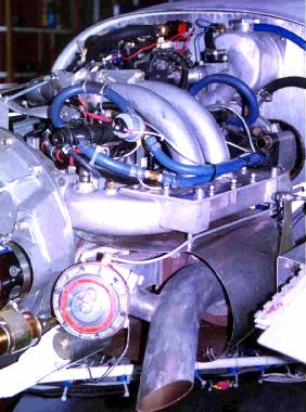
In this one, you can see a couple of long intake runners going down to the manifold, and a turbo beneath a heat shield. Gary, at Atkins/Camden, said it's not the most efficient design. by the way, the injectors are at the very top of the runners. That kind of length is not an option on my 20B.
In this one, you can see a couple of long intake runners going down to the manifold, and a turbo beneath a heat shield. Gary, at Atkins/Camden, said it's not the most efficient design. by the way, the injectors are at the very top of the runners. That kind of length is not an option on my 20B.
Thread Starter
Joined: Aug 2001
Posts: 15,725
Likes: 91
From: Near Seattle
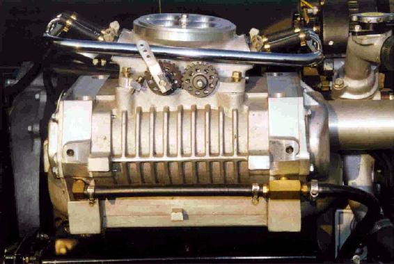
This pic shows a 9" supercharger with a Holley Projection TB. Now imagine a carb spacer where the SC is. It'll be a lot smaller than the SC, for sure. Will it flow well enough into the front and rear rotors?
Thanks for looking.
Thanks for looking.
Thread Starter
Joined: Aug 2001
Posts: 15,725
Likes: 91
From: Near Seattle
Ok, let's assume the 7" by 2 5/8" opening at the top of the Atkins manifold is centered front to back. I measured across the bottom of my stock LIM and found the distance to be 17 1/4" from front secondary to rear secondary. Then I found the middle of this (8 5/8" from each end) and marked it on the gasket surface. Measuring 3 1/2" forward and back from this center point, I noticed that four out of the six 20B ports were within 7" of each other. Interesting.
The secondaries are a lot larger than the primary ports of course, but having three primaries and one secondary already within the 7" range, is quite promising. The primaries will have an equal shot at getting a good amount of fuel out of the AF mixture. Which leaves the problem with the secondaries.
How about if I installed a partition inside the manifold around the middle rotor's secondary port runner so it would't get the same direct shot as the primaries? What if I made the opening of the partition a little further away from the primaries so when the momentary reversion of the middle rotor happens (you know, when the ports close and it pushes the AF mixture the wrong direction for a microsecond), it doesn't screw things up for the primary ports of the other two rotors? Maybe that part doesn't make sense, but what if the opening of the partition was more near the other secondaries? It might work. Right?
Maybe 'partition' isn't the right thing to call it, but this picture should give you the basic idea. The green represents a tube inside the manifold. The red rectangle is the 7" by 2 5/8" opening at the top of the manifold. The blue circles are the ports (in case you couldn't figure it out ).
What I'm trying to do is make the secondary of the middle rotor less accesible to the incoming AF mixture. As long as the (green) tube opens just beyond the rectangular hole at the top of the manifold, it should effectively be outside of the main incoming AF mixture.
Do you guys think this is too extreme?
The secondaries are a lot larger than the primary ports of course, but having three primaries and one secondary already within the 7" range, is quite promising. The primaries will have an equal shot at getting a good amount of fuel out of the AF mixture. Which leaves the problem with the secondaries.
How about if I installed a partition inside the manifold around the middle rotor's secondary port runner so it would't get the same direct shot as the primaries? What if I made the opening of the partition a little further away from the primaries so when the momentary reversion of the middle rotor happens (you know, when the ports close and it pushes the AF mixture the wrong direction for a microsecond), it doesn't screw things up for the primary ports of the other two rotors? Maybe that part doesn't make sense, but what if the opening of the partition was more near the other secondaries? It might work. Right?
Maybe 'partition' isn't the right thing to call it, but this picture should give you the basic idea. The green represents a tube inside the manifold. The red rectangle is the 7" by 2 5/8" opening at the top of the manifold. The blue circles are the ports (in case you couldn't figure it out
).What I'm trying to do is make the secondary of the middle rotor less accesible to the incoming AF mixture. As long as the (green) tube opens just beyond the rectangular hole at the top of the manifold, it should effectively be outside of the main incoming AF mixture.
Do you guys think this is too extreme?
Thread Starter
Joined: Aug 2001
Posts: 15,725
Likes: 91
From: Near Seattle
You know how the GSL-SE's cold air intake tube goes from in front of the radiator to the air filter box? The cold air tube is perpendicular to the incoming air, yet it still works fine (for stock power anyway). That was my inspiration for the tube in the atkins manifold.
Trending Topics
Thread Starter
Joined: Aug 2001
Posts: 15,725
Likes: 91
From: Near Seattle
Thanks for responding.
Do you mean the stock lower manifold modified as described above? Or the LIM and UIM with fuel injection (heh, is that your defenition of the stock manifold)?
I'm going to get my primary injectors back so I'll have them for when I go FI with a supercharger. That is IF if go that route. I may try to get my UIM back too.
I'm going NA with a carb for now. Cheaper and easier to set up, unless you count the manifold itself. Heh.
Are you familier with creating an homogenous AF mixture using two baffle plates spaced an inch apart with their surfaces littered with randomly sized holes? I could fit them inside the 3 or 4" aluminum pipe 'plenum' as described above. The incoming AF mixture will encounter the baffles and magically flow into whichever runners want it the most. Heh, sorry.
Last edited by Jeff20B; Dec 11, 2003 at 01:27 AM.
Thread Starter
Joined: Aug 2001
Posts: 15,725
Likes: 91
From: Near Seattle
Here is a third idea. What if I were to actually build myself a manifold? Imagine that!
Mazdatrix sells steel and aluminum intake flanges. I know how to work with steel, so I'd get the steel one even though it's a little more expensive.
What do you think about this drawing? I didn't include primary runners here for simplicity. I think the middle pipe needs to be longer for equal length runners.
Since you haven't gotten many responses I thought I'd chime in and just say build one from pipes and flanges. Mazdatrix for a while ws trying to go the n/a route on their 3 rotor drag car and use some serious nitrous. They later changed to the Roots supercharger. Here is a picture of their old 4 barrel manifold though.

Thread
Thread Starter
Forum
Replies
Last Post
trickster
2nd Generation Specific (1986-1992)
25
Jul 1, 2023 04:40 PM