When you click on links to various merchants on this site and make a purchase, this can result in this site earning a commission. Affiliate programs and affiliations include, but are not limited to, the eBay Partner Network.
All gauge lights/idiot lights remain ON post-swap to FC 80 amp alternator.
Car is an 85 GSL, fusible links were converted to an FC fuse box successfully a couple years ago.
With the car running pre-swap, I got a reading of 14.08V at the battery. Post-swap, the reading is 15.25V. This sounds like overcharging.
I wired the new connector to the existing alt wires per this thread, BW wire to left side of connector, WB to right side. We also added a 4 gauge wire directly from output on alternator to positive battery terminal.
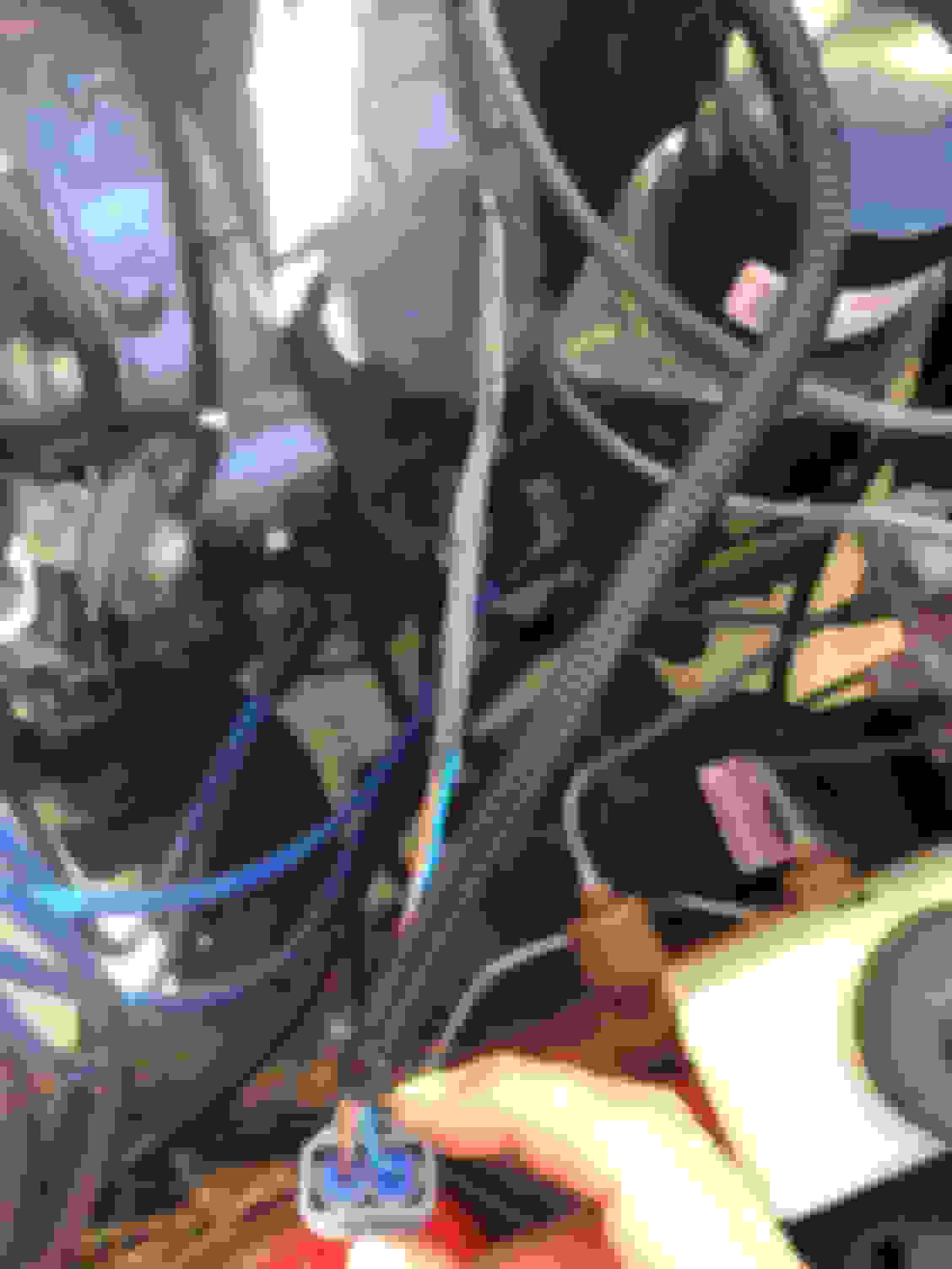
Red 10 gauge wire shown in pictures runs from output on alternator to the WR wire in the harness that runs into the cab.
Any/all help is greatly appreciated! Voltage reading w/oem 55a alt. Gauge cluster pre-swap. Add coolant illuminated due to broken wire on sensor Voltage reading w/S5 80a alt. Gauge cluster post-swap. All idiot lights illuminated. Engine Bay
Not your issue, but I hope you added a fuse on the wire from alt to battery. Seems like an issue waiting to happen.
I'm sure someone will chime in on the over charging.
Thanks for the reply. It was originally run to the fc fuse box where there is a main fuse separating it from the battery. I still have to shorten that wire as shown in the picture, and this would be a great time to put an in-line fuse.
To help clarify my original post- why would the dash lights be staying on constant, and is the voltage reading post-swap normal?
Last edited by jdmminot; Sep 14, 2019 at 09:29 PM.
Alternator is wired incorrectly,diagram you linked to is showing alternator wired wrong,what you haven't yet found out is that in @ 72 hours you will have a dead battery with it wired that way. FB,FC alternator regulator operate differently than FD.
When ignition key on FB is turned off,the 12 volts(exciter voltage) supplied to regulator goes to ground. On an FD alternator this leaves the regulator energized=healthy parasitic draw on battery.
Why do you have two wires coming off alternator output terminal,where does that go? The fitting at the alternator needs to be insulated,that's begging for something to be dropped across it and alternator,engine housing,any ground. By the time you stop the sparking,likely you'll have rectifier damage. As a previous poster noted,alternator direct to battery is asking for a burn car to the ground scenario.I saw you stated you were going to fuse it to the battery.The best place to route that alternator output wire to is the car side of the main buss that feeds all circuits in the car and on other side of main fuse,a 4 gauge section of wire,identical to alternator output wire, to go to the positive battery terminal. This gives best use of generated current to fusebox and all circuits powered from it,making the most use of fusebox conversion.
For what it's worth,this is how car was wired originally.
You should also swap that 80 amp main fuse for 100 amp fuse. When you upgrade alt output you need to upgrade main fuse,it is possible in certain scenarios for the alternator put out 80 amps and maybe more.
Correct alternator wiring... the plug on back of alternator has two terminals. If you look closely at alternator case you will see an S cast into alt housing. Looking from back of alternator,it is on the left side of connector,this is the S terminal. The other terminal is the L terminal.
S =sense,on that terminal the alternator regulator is looking for battery reference voltage. The voltage coming to that terminal as you currently have it wired with the key on will always be less than battery voltage because of the path the current takes from the battery to inside the car and through ignition switch and back out to the alternator.Add to that 35 years of resistance build up in wiring and easily voltage going to sense terminal in regulator will be 1.0-1.5 volts below battery voltage. Look at you multimeter readings you posted here. The alternator is charging a little over 1 volt too high because it thinks what's being fed to it from the ignition switch is actually the battery voltage and it's chasing that value to try to charge battery to cut point in regulator.
You need to feed the s terminal true battery voltage,that can be done by running a wire from battery positive to that terminal,but it's much easier to take battery reference voltage by looping sense wire around to alternator output stud which has exact battery voltage because it's connected to the battery...make that switch and your alternator will be charging 14.1-14.5 volts,exactly where battery should be kept when car is running.
L=light,as in idiot or battery light in warning light cluster. All the warning lights in the cluster are powered through ignition switch.When key is on engine not running=alternator not turning,the L terminal is grounded.The ground completes the warning light circuit and warning lights are illuminated and stay that way except for seat belt light that has a timer and times out in @ 5 seconds. When engine starts,alternator initiates charging,the ground is now charge voltage and all lights go out.
There are two things that can cause your light on engine running scenario,a wiring issue or a voltage regulator in alternator issue. Disconnect plug from back of alternator and turn key on. I'm not home at this point so can't access wiring diagrams but wires coming to alternator out of engine harness are black/white tracer and white/black tracer. I'm tired and can't remember which is which but is easy to figure out. Use a test light or multimeter,i prefer test light and probe 2 terminals for voltage. As you have it wired,the left/sense terminal should show @12.2 volts,so the other wire is Idiot light feed wire. Look in the car with key on,the lights will(should) be out. Take a jumper wire and ground the plug's L terminal to engine and check warning lights. They will be illuminated. If they stayed illuminated when you unplugged the connector,you have a wiring problem,if they went out you have a problem with alternator voltage regulator.Where did alternator come from,new/reman/used? For what it's worth,this is a symptom that occurs when alternator has been shorted or a bad diode(s) and can't meet charge threshold in regulator. In your case i don't think that's the case. Defective regulator?
So you have two problems,not one. Rewire the alternator as described,that will address the overcharge complaint. Do the tests for idiot light function and post back findings.
Last edited by GSLSEforme; Sep 14, 2019 at 11:26 PM.
GSLSE- Thanks for the response and info! Concerning the power draw, this is an FC alternator, not a FD. Not sure if your first paragraph was fd specific.
I took the large 4-gauge wire out of the equation for now. The red 10 gauge wire running from the B-Output terminal is hooked up exactly like the original white w/red stripe. This goes into the engine bay harness and back towards the dash. The white w/red striped wire returns from the cab and goes into the circuit/fused side of the FC fuse box. No change from stock FB wiring, just that 2' of the wire was replaced with another color and the other end is tied into a fuse box vs fusible links.
Here are my findings when disconnecting the alternator plug-
The idiot lights went off when I disconnected the plug.
I am getting switched 12v through the right L terminal, instead of the left. The reading was 10.8V, Battery showed 11.79V-see pics. I pulled the loom apart and confirmed that the white w/black wire goes to L terminal, Black w/white wire is going to S. These were soldered and heatshrinked according to the diagram listed below. Are these backwards?
I ran a jumper wire from the plugs L terminal to ground, the idiot lights did not come on.
Alternator was purchased from an ebay seller- ace_alternators professionally remanufactured. They have perfect feedback and offered a one year warranty, so if it is in fact the alt I still have a few months left to swap.
Please let me know what other information I can provide, thanks all for the help. Original alternator wires running to new plug. L terminal at plug showing switched 12V. I traced alternator harness back to factory connector and confirmed I am getting switched 12V from the White w/black wire.
The S5 and FD alternator use the same wiring strategy than the S4 FC, that is what he meant.
That is an FD alternator. Right off the top the Mitsubishi connector gives it away. If that were an FC alternator you could have connected your original connector to back of alternator,you know the one you cut off to attach leads from your new connector for this alternator... Somewhere along the way there is some. confusion.
My diagnosis and repair to overcharge stands,it will fix your overcharge and the dead battery you were going to have in a couple days if not daily driving.
I�m on my phone i�ll Have to reread op comment about warning lights later.
In looking at pics from today,the large gauge output wire is gone and in its place is a smaller wire,confused.
Again,the schematic you wired the FD alternator with is flawed and your wiring incorrect due to it.To prove it,leave the plug out of alternator and put a jumper wire from S terminal to output stud on alternator and start car and note charge rate compared to wiring,plug installed previously. The result will not be more than 14.6 volts and more likely @14.3 volts.
Regarding the L terminal,the reason you are seeing switched voltage there is that is the wire from all the warning cluster bulbs,of course there is voltage there,you notice it's not 12 volts,that is voltage coming thru all bulb filaments seeking ground to complete circuit fro them to illuminate. Were you to use test light from ground to L terminal ,you would see it would barely light,if at all. At same time warning lights would be illuminated but not as bright as filament in test light adds resistance to the circuit and it's not a full ground.
"I ran a jumper from L terminal in plug to ground and lights did not illuminate"-this makes no sense. Your new connector installed in alternator causes warning lights to be illuminated, disconnected= no lights from no ground.
Again,use a test light here. Connect test light lead to output terminal on alternator and probe of testlight touching L terminal in alternator. The testlight will illuminate as L terminal completes circuit to ground and why your warning lights illuminate when connector installed and key on.
I have no idea why your ground test of L terminal in connector doesn't turn on warning lights. In the end it is of no consequence as L terminal in alternator is grounded and warning lights come on in key run position.
The other wire connected to sense terminal connector is key hot 12 volts and this will disappear when key is turned off. If this is not the case,something is wrong with the wiring in this car. The 12 volts should drop down to nothing and the S circuit is essentially a ground and why this circuit will keep regulator powered up and run battery down. On all FDs there is no wire with 12 volts coming from the ignition switch to S terminal. The S terminal in alternator is jumpered to alternator output terminal and it has battery voltage at all times-sensing state of charge of the battery and telling regulator in alternator what battery needs to be properly charged.
In order for the higher amp alternator to get all its output to car/battery,it needs to have a larger wire than what you have in place.That wire was sufficient for oe 55 amp alternator. For larger output alternator,the 4 gauge wire from alternator to main fusebox on car side is ideal and the other main fuse terminal should have same gauge wire attached to it and run to positive battery terminal and as mentioned before,main fuse should be upped to 100 amps.
I�m starting to get it- I installed an LS Charging alternator and need to wire it appropriately.
The thread I used for information was specifically for putting the 80amp FC alt in the 12a rx7, but this information was wrong.
I can assure you this is from a 2nd gen, not a FD. FD�s do utilize the same connector, but it is on the side of the alternator and not the back. I will re-wire per your suggestions and report back. Thanks again.
I believe this will correct the issue, how does it look?
1. Leave W/B wire running to L terminal as it is now.
2. Disconnect B/W wire currently running to S terminal, tape it off in harness.
3. Run 12V wire from FC fuse box to S terminal, 10-15a fuse max
4. Run large 4 gauge wire from Alt output stud to circuit side of FC fuse box.
5. Run Short 4 gauge wire from Battery side of FC fuse box to positive terminal on battery.
6. Add 100a main fuse
7. Drive 7
Yes,do all of that. You do not need to run a wire from fusebox to S terminal. Take the pigtail for S terminal connector,that you had soldered into harness,put a ring terminal on it. Remove alt output stud nut,slip sense wire ring terminal on stud and replace and tighten nut. No need to fuse jumper.
I know you're trying to assure me your replacement alternator is 2nd gen. Again,were that true,you could have plugged your original connector into back of alternator.It would be an S4 alternator.
To have this alternator work properly,you are wiring it as it is in a FD.
There are two versions of FD alternators. S5 and S6. You have an S5. The S6 has S/L terminals on side of case.
Post back your results for others' benefit.
Last edited by GSLSEforme; Sep 16, 2019 at 01:19 PM.
Now, I'm just posting this based on my own research from back when I did my swap, but I believe the op is correct about the second gen bit. If I'm not mistaken, second gen is S4/S5 and FD's are S6 - S? (for other markets). However, like GSLSEforme mentioned, the alternators did change significantly between S4 and S5 and so the wiring of an S5 alt is the same as an 'FD' alt, although the connector is on the back of the alternator case. I also read a while back that doing the 'alt output to S-pin jumper' is the "wrong" way to do it. Not sure exactly why - perhaps it gives a higher reading due to the shorter distance - but it seemed like the agreed way was to run a wire from the positive of the battery to the S-pin with a fuse inline. You also need to add a relay or diode in that sense line regardless of the source or else you still end up with a drained battery in a couple days - unless I'm also mistaken there... perhaps you can tell that this isn't fresh in my memory. For my setup I used the original switched 12V lead to trigger a relay that controls the sense line. I originally had it wired up so that the stock 12V source was also the sense line itself but still running through the relay (hence preventing the drain) but the old wiring was leading to a false representation of the voltage which lead to the same over charging issue the op has. I then ran a separate sense line and all has been well since.
Perhaps a relay or diode isn't necessary unless you use the stock 12V wire (which switches to ground when the key is off), but using a relay will at least give the alt some 'down time' without being powered. I think some folks have mentioned that their alternators would get warm when not running if the sense line was connected directly to the battery. And heat means current, so heck, maybe you do need a relay... honestly I'm not certain - I'd have to do some research of my own to settle that one and refresh my memory.
Anyway, I hope that convoluted answer at least explained some things if it didn't make any sense otherwise. Do post back with the results though - hate seeing threads that are just left hanging.
Last edited by Benjamin4456; Sep 18, 2019 at 04:31 PM.
Now, I'm just posting this based on my own research from back when I did my swap, but I believe the op is correct about the second gen bit. If I'm not mistaken, second gen is S4/S5 and FD's are S6 - S? (for other markets). However, like GSLSEforme mentioned, the alternators did change significantly between S4 and S5 and so the wiring of an S5 alt is the same as an 'FD' alt, although the connector is on the back of the alternator case. I also read a while back that doing the 'alt output to S-pin jumper' is the "wrong" way to do it. Not sure exactly why - perhaps it gives a higher reading due to the shorter distance - but it seemed like the agreed way was to run a wire from the positive of the battery to the S-pin with a fuse inline. You also need to add a relay or diode in that sense line regardless of the source or else you still end up with a drained battery in a couple days - unless I'm also mistaken there... perhaps you can tell that this isn't fresh in my memory. For my setup I used the original switched 12V lead to trigger a relay that controls the sense line. I originally had it wired up so that the stock 12V source was also the sense line itself but still running through the relay (hence preventing the drain) but the old wiring was leading to a false representation of the voltage which lead to the same over charging issue the op has. I then ran a separate sense line and all has been well since.
Perhaps a relay or diode isn't necessary unless you use the stock 12V wire (which switches to ground when the key is off), but using a relay will at least give the alt some 'down time' without being powered. I think some folks have mentioned that their alternators would get warm when not running if the sense line was connected directly to the battery. And heat means current, so heck, maybe you do need a relay... honestly I'm not certain - I'd have to do some research of my own to settle that one and refresh my memory.
Anyway, I hope that convoluted answer at least explained some things if it didn't make any sense otherwise. Do post back with the results though - hate seeing threads that are just left hanging.
You are mostly correct.
Yes the S5 is an FC, S6 is FD.
Yes the S5 alternator is the same style alternator as the FD, both requiring a sense wire.
Yes it is incorrect to loop the sense wire to the B+ terminal. However, if the battery is in the stock location, it's close enough for government work. In a vehicle with a relocated battery, forget about it.
If you're referencing the thread I believe you're referring to with diodes and relays, that was a combination of attempt to make the wrong wiring work (lack of constant B+ sense wire), and intentionally dropping the sense voltage by a diode drop to modify the charge voltage.
If you're referencing the thread I believe you're referring to with diodes and relays, that was a combination of attempt to make the wrong wiring work (lack of constant B+ sense wire), and intentionally dropping the sense voltage by a diode drop to modify the charge voltage.
That may have been what I was thinking of, it was from a thread I read some time ago. The diode method is also a way to try and use the stock wiring by preventing drain back through the 12V source which becomes a ground when the key is off - not sure why it does that, but it does...
Anyway, I use a relay and it works fine, although perhaps it's unnecessary.
1. Leave W/B wire running to L terminal as it is now.-DONE
2. Disconnect B/W wire currently running to S terminal, tape it off in harness.-DONE
3. Run 12V wire from FC fuse box to S terminal, 10-15a fuse max
Prior to this step, I wanted to see what voltages I was getting by using the output stud connected to the sense wire vs battery connected to sense wire.
I ran a jumper wire from the output stud to the Sense wire on the harness and read 14.26V at the battery.
I ran a jumper wire from the battery post to the sense wire on the harness and read 14.33V at the battery. (Way to call it GSLSEforme)
I went with the option that provided that little extra voltage and ran a permanent wire from Sense on alternator to the FC fuse box where hot from battery connects, with an inline ato fuse holder just outside the box. What size fuse should I run here, 5-10amp?
4. Run large 4 gauge wire from Alt output stud to circuit side of FC fuse box. Reconnecting this as soon as I get the wire for step 5
5. Run Short 4 gauge wire from Battery side of FC fuse box to positive terminal on battery. Almost done
6. Add 100a main fuse Easy!
7. Drive 7
Soon! Testing voltage using battery for sense wire Testing voltage using alt output terminal for sense wire Sense wire soldered to new wire running to FC fuse block. BW wire heat shrinked and ready to be hidden in loom Sense wire joining up with the output wire. Large 4 gauge wire to be installed soon, will leave existing output wire that runs into dash in place.
Just skimming, and wanted to confirm no one should be making a short loop of wire between B and S. It works short term but it overworks the regulator. Use a small gauge wire, a diode (so current can only travel from battery to alternator S post), and a low amperage fuse and go directly to the battery. The battery acts as a capacitor so the quick changes in current/load seen at the B post is very different from what is seen on the positive battery post.
This. The above thread has much more reliable diagrams than others mentioned in this thread.
80A alternator is from an FC (series 5) and has the same load sensing (L/S) type alternator as the FD.
You don't loop the S terminal directly on the B terminal. The whole idea of the S terminal is to account for voltage drop across the system and adjust the regulated output at the B terminal. Run the S terminal back to a separately fused battery positive circuit, as shown in the AusRotary diagrams linked above.
Tons of information, I wish I would've started with this thread vs. the one I found.
Originally Posted by chuyler1
Just skimming, and wanted to confirm no one should be making a short loop of wire between B and S. It works short term but it overworks the regulator. Use a small gauge wire, a diode (so current can only travel from battery to alternator S post), and a low amperage fuse and go directly to the battery. The battery acts as a capacitor so the quick changes in current/load seen at the B post is very different from what is seen on the positive battery post.
No loop here, I went from fuse box to S with 16 gauge wire and inline 5a fuse. I didn't use a diode. What, if any, are the negative effects of skipping this?
Originally Posted by KYPREO
This. The above thread has much more reliable diagrams than others mentioned in this thread.
80A alternator is from an FC (series 5) and has the same load sensing (L/S) type alternator as the FD.
You don't loop the S terminal directly on the B terminal. The whole idea of the S terminal is to account for voltage drop across the system and adjust the regulated output at the B terminal. Run the S terminal back to a separately fused battery positive circuit, as shown in the AusRotary diagrams linked above.
All information I didn't know when I started this project! Do you have any input on the in-line Diode?
This was on my REPU so slightly different configuration but principal applies and will explain why I mentioned the diode...
The b-post wire was 2 gauge and ran from the alternator into the cabin to a fuse box behind driver seat, then to a 150a fuse behind passenger seat, then to the battery right behind passenger. The S wire from alternator was 16 gauge and traveled the same route uninterrupted except for a 5a fuse a few inches off the battery. That fuse kept popping, I assume a certain amount of current was flowing through it from the alternator to the battery in an attempt to bypass the fusebox when the charge was low...I don't know. It happened twice and when it did voltage was going up to 15v. So I put a diode on that 16ga wire and I now see 14.2v to 14.4v no matter what accessories are on.
Long story short, if you follow the wiring in the aussi link, you are probably good...but check that fuse after a few miles to make sure it hasn't blown.