Transistor trick for 2GCDFIS.
 07-11-05, 04:29 AM
#126
Bizump. Holy crap guys, how did I miss this welth of information? I guess I havent been around for a while! Man, this is exciting, seeing something completely new being developed right before my eyes. I wish I knew more about electronics to help with the build, but I dont posess such an in depth understanding as to say "well, this isnt really working, why not try component X". I just know how to do "simple" stuff. Jack of all trades, master of none. Anyway, as I said, I wish I could contribute more. I know my uncle has an infrared thermometer, but I havent a 2nd gen vehicle to take temps from. He also has some NICE testing equipment Im sure would get those ECU outputs you talked about earler, but alas, no 2nd gen vehicle. So, in closing, good luck, Im reading the other thread too!
~T.J.
~T.J.
 07-11-05, 04:33 AM
#127
Banned. I got OWNED!!!
Join Date: Mar 2005
Location: SF CALI
Posts: 564
Likes: 0
Received 0 Likes
on
0 Posts
Originally Posted by RotorMotorDriver
Bizump. Holy crap guys, how did I miss this welth of information? I guess I havent been around for a while! Man, this is exciting, seeing something completely new being developed right before my eyes. I wish I knew more about electronics to help with the build, but I dont posess such an in depth understanding as to say "well, this isnt really working, why not try component X". I just know how to do "simple" stuff. Jack of all trades, master of none. Anyway, as I said, I wish I could contribute more. I know my uncle has an infrared thermometer, but I havent a 2nd gen vehicle to take temps from. He also has some NICE testing equipment Im sure would get those ECU outputs you talked about earler, but alas, no 2nd gen vehicle. So, in closing, good luck, Im reading the other thread too!
~T.J.
~T.J.
TRUST ME !
https://www.rx7club.com/showthread.p...rick+installed
07-11-05, 11:38 AM
#128
Waffles - hmmm good
iTrader: (1)
Could I use this circuit without modification with j105 igniters ? I have an 80 which has the j105s mounted on the fender. Just wondering if they would work as well as the 109s.
BTW, this is one of the best threads on the board these days. Great topic. The ignition circuit has always been, I think a weak spot for the 1st gens. Direct fire is the answer and this looks to be the best solution so far.
BTW, this is one of the best threads on the board these days. Great topic. The ignition circuit has always been, I think a weak spot for the 1st gens. Direct fire is the answer and this looks to be the best solution so far.
07-11-05, 12:25 PM
#129
Thanks.
Yes, the J-105 operates very similarly to a J-109. I'm not sure of the details, and you might need to keep an eye on some of the components to check for heat during testing, but that's normal behavior from what I've seen from people testing thus far on J-109s. A J-105 should work out pretty well hooked to the "transistor trick" circuit. I see no reason why it wouldn't. Go for it.
Yes, the J-105 operates very similarly to a J-109. I'm not sure of the details, and you might need to keep an eye on some of the components to check for heat during testing, but that's normal behavior from what I've seen from people testing thus far on J-109s. A J-105 should work out pretty well hooked to the "transistor trick" circuit. I see no reason why it wouldn't. Go for it.
07-11-05, 01:14 PM
#130
Yep, the J-105 should work just fine. Any ignitor would probably due, in fact (such as an HEI). Because of the way the circuit is designed, the load on the first gen ignitor is very small. This should help them last much longer.
I'll repost the circuit designs later today (one with the variable PW only and one with both). I see that I forgot a resistor on the previous drawings. So far the variable PW mode seems to work the best (also is the simplest). The fixed PW mode runs poorly at idle and low end situations (not enough coil charge time I suspect). It does work as good or maybe better on the high end, though.
Any other input would be highly appreciated (circuit design improvements, testing of the 2nd gen coil temp (I could probably test mine, need someone to get a good reading on a 2nd gen, though), putting a scope on the IgT line of the 2nd gen ECU to see what it does with PW under certain conditions, etc.).
Kent
07-11-05, 03:39 PM
#131
Here are the updated drawings.
Both modes:
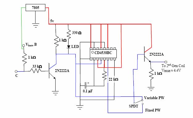
Variable only:
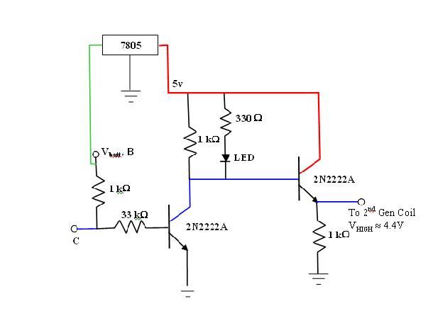
I will probably assemble some more of these boards. I just need to find a source of ignitor connectors. If you are interested in a built board, shoot me a pm. I was also thinking about putting together a write-up on how to build these. They are pretty simple to build (especially the variable PW mode only circuit). I am sure a lot of people would be comfortable building them if they had step-by-step instructions.
Kent
Both modes:
Variable only:
I will probably assemble some more of these boards. I just need to find a source of ignitor connectors. If you are interested in a built board, shoot me a pm. I was also thinking about putting together a write-up on how to build these. They are pretty simple to build (especially the variable PW mode only circuit). I am sure a lot of people would be comfortable building them if they had step-by-step instructions.
Kent
07-11-05, 03:57 PM
#132
Yes. Special thanks to Jeff for starting this thread. I know about the electronics stuff, but I learned from Jeff and renns about the ignition stuff in order to get a working circuit. I knew almost nothing about the ignition systems before this.
The heat issue isn't really with the J-109 or the circuit itself. All of those components stay cool (except for the heat the J-109 picks up from the engine). The 2nd gen ignitor does get quite hot. It does appear to be normal though. TurboSE felt the coil pack of his friend's TII after a drive. He said it was hot enough to burn you after touching for more than 3 or 4 seconds. It would be nice to get some actual temps of our setup versus a stock 2nd gen. Then we would know for sure if the temps that we are seeing are safe.
Originally Posted by Jeff20B
Thanks.
Yes, the J-105 operates very similarly to a J-109. I'm not sure of the details, and you might need to keep an eye on some of the components to check for heat during testing, but that's normal behavior from what I've seen from people testing thus far on J-109s. A J-105 should work out pretty well hooked to the "transistor trick" circuit. I see no reason why it wouldn't. Go for it.
Yes, the J-105 operates very similarly to a J-109. I'm not sure of the details, and you might need to keep an eye on some of the components to check for heat during testing, but that's normal behavior from what I've seen from people testing thus far on J-109s. A J-105 should work out pretty well hooked to the "transistor trick" circuit. I see no reason why it wouldn't. Go for it.
07-11-05, 07:56 PM
#133
Rotary Enthusiast
Join Date: Jun 2002
Location: Yokosuka
Posts: 1,058
Likes: 0
Received 0 Likes
on
0 Posts
To be on the safe side, I'd like to add a heatsink or heatsink fan combo from a CPU fan... I noticed that the ignitor itself is facing away from the backside and towards the coil. So, then, the ignitor would need to be removed and placed on its own heatsink?
07-16-05, 12:28 AM
#134
Full Member

Join Date: Jan 2004
Location: Louisiana
Posts: 69
Likes: 0
Received 0 Likes
on
0 Posts
There we go with the ignitor connectors again. To bypass this problem wouldn't it be better to use an HEI and a couple of spade connectors instead of the hard to find stock connectors? Of course you would have to test this configuration to see if it works as well as the J-109's.
Just thought I'd throw this in to prevent a potential bottle neck on a wonderful design!
Sanspistons for longer, stronger Se* -er, Sparks!
Just thought I'd throw this in to prevent a potential bottle neck on a wonderful design!
Sanspistons for longer, stronger Se* -er, Sparks!
07-16-05, 04:34 AM
#135
Driveline Killer
Join Date: Jul 2004
Location: OC the wicked 714
Posts: 1,463
Likes: 0
Received 0 Likes
on
0 Posts
this is very interesting but now I am more confused than ever.....There is an ever growing amount of options for ignition setups on 1st gen RX7s and now I am just not sure what I want to do...............
07-16-05, 11:06 AM
#136
Rotary Enthusiast
Join Date: Jun 2002
Location: Yokosuka
Posts: 1,058
Likes: 0
Received 0 Likes
on
0 Posts
This setup has been tested already to produce a much better spark than stock. Though, I can't say whether or not it is better than the original dual fire system that jeff20b developed, others have unanimously proclaimed it better than stock.
Just do your homework and figure out what you think would work best for your setup..
Just do your homework and figure out what you think would work best for your setup..
07-16-05, 12:30 PM
#137
Originally Posted by Sanspistons
There we go with the ignitor connectors again. To bypass this problem wouldn't it be better to use an HEI and a couple of spade connectors instead of the hard to find stock connectors? Of course you would have to test this configuration to see if it works as well as the J-109's.
Just thought I'd throw this in to prevent a potential bottle neck on a wonderful design!
Sanspistons for longer, stronger Se* -er, Sparks!
Just thought I'd throw this in to prevent a potential bottle neck on a wonderful design!
Sanspistons for longer, stronger Se* -er, Sparks!
Originally Posted by TurboIIGuy
this is very interesting but now I am more confused than ever.....There is an ever growing amount of options for ignition setups on 1st gen RX7s and now I am just not sure what I want to do...............
I am still looking for the connectors. If anyone can find a place that sells these connectors bulk/cheap, I will give that person a transistor trick circuit free of charge.
Any questions, feel free to ask.
Kent
07-16-05, 01:06 PM
#138
Which connectors are you looking for? I must have missed where you mentioned the type that you need.
In a 1st gen, I'd say 2GCDFIS with the transistor trick would be best due to lack of space and less work would be required. In an old school Mazda (REPU, Cosmo and RX-4) where the coils are closer to the engine and adding a 3rd is actually quite easy, DLIDFIS is probably best. I'm going to add a 3rd coil to my recently acquired RX-4 for my brother to use, and then I'm going to install 2GCDFIS (with transistor trick) in a 1st gen as soon as I get one. It just seems like the best choice considering component locations in the engine bays and all that.
In a 1st gen, I'd say 2GCDFIS with the transistor trick would be best due to lack of space and less work would be required. In an old school Mazda (REPU, Cosmo and RX-4) where the coils are closer to the engine and adding a 3rd is actually quite easy, DLIDFIS is probably best. I'm going to add a 3rd coil to my recently acquired RX-4 for my brother to use, and then I'm going to install 2GCDFIS (with transistor trick) in a 1st gen as soon as I get one. It just seems like the best choice considering component locations in the engine bays and all that.
07-16-05, 05:02 PM
#139
Lives on the Forum
Help!!
Okay guys, I think this would have been easier to accomplish if I hadn't already been running the 2nd gen coil.
I have had to reinstall the 2nd gen ignitor into the coil pack, and solder new wires on where I had clipped the originals off. But I am unclear about a few things after going through the pdf instructions that Kent sent to me.
He states that the black wire on the 2nd gen ignitor is "not used" and to leave it alone. This is currently clipped off on my ignitor, so do I need to hook that back up the way it originally was? Or is it really not used?
Also, the brown wire from the ignitor......where does this connect to? In the photos it is actually red (without the stripe marks) because that's all I had to use at the time.
I will attach some photos...
Also, I currently have the large 10 ga red wire going from the black/white power wire that fed the original coil. This is connected to the + on the 2nd gen coil. Is this supposed to feed into the gizmo box instead?
And, the original yellow/green wire from the 1st gen ignitor is running into the coil pack, through the resistor, then to the - post on the 2nd gen coil.
I'm sure this is fubared at the moment, so I'm not even going to try to start it up until I'm sure that I've got it right. Thanks in advance for any assistance you can provide...
07-16-05, 05:42 PM
#140
Suicidal Death Missile

Join Date: Mar 2004
Location: Newport News, Virginia
Posts: 1,782
Likes: 0
Received 0 Likes
on
0 Posts
Well, with my box installed I essentially have: (I have a relay installed but it's not necissary)
The stock wires from the stock 2nd gen coil go back to their origins. IE, you would not remove any wires from the coil period. The tan wire is the power wire. The black wire that had the connecter on it is not used. The other wire that was in the connector with the tan wire is the signal wire coming from the transistor trick box. You must also supply power to the transistor box via ignition on/start only power. It would be a good idea to do this with the coil as well, since the battery will probly drain. Just splice the stock 1st gen coil + wire to the power wire (tan/brown) on the 2nd gen coil AND the transistor trick power wire. Hook up your signal wire from the transistor to the 2nd gen coil signal wire. Plug the connectors with the green wires to the stock 1st gen ignitor (you'll have to unplug the stock wiring to the stock 1st gen ignitor). Almost done. Mount the 2nd gen coil assembly and ensure that the box is GROUNDED. Hook up the ground wire from the transistor box, and lastly, hook up your plug wires.
This should take around 30-45 minutes depending on your ability. It took me longer because I also installed a relay and used soddered connectors.
07-16-05, 05:53 PM
#141
Lives on the Forum
Okay, I'm just running into problems here because I'm not sure how the 2nd gen coil was wired originally. I've been running the old style 2nd gen ignition mod for some time now, and that included removing the ignitor from the coil pack. So now I have to reinstall and wire up the ignitor before I can begin to make sense of these instructions....
I'm going to print up your reply and take it out to the car. Hopefully I can get this figured out.....Thanks for the help Man!
I'm going to print up your reply and take it out to the car. Hopefully I can get this figured out.....Thanks for the help Man!
07-16-05, 10:49 PM
#143
Glad that you are getting a chance to install the circuit. Sorry I wasn't around earlier to give you a hand. Looks like you are on the right track. The red wire that you have connected to the B terminal (near the base of the ignitor) is switched 12v. You can use the stock BY coil + as your source or use a relay as lovintha7 did. The red wire from the circuit will also connect to switched 12v. The other connection near the bottom (red wires with marks) is the trigger wire from the transistor trick circuit. It appears that you have this correct. The black wire (C terminal) will connect to the coil -. The resistor can either be inline on the coil + or coil -. Mine came with it on the coil -, but I have seen the 2nd gen coils come with it installed on the coil + as well. Following the pic you found should help you figure it out.
Jeff20B: I mean the connectors the plug on the J-109. They are arranged in a 'T'. They are like the pre-S5 alternator plugs. Female spade connectors work as well. Just be sure to install them correctly.
Jeff20B: I mean the connectors the plug on the J-109. They are arranged in a 'T'. They are like the pre-S5 alternator plugs. Female spade connectors work as well. Just be sure to install them correctly.
07-17-05, 04:55 AM
#145
Lives on the Forum
The biggest problem that I ran into with this mod was the fact that my 2nd gen coil pack had already been modified for the original upgrade. I had to reinstall the ignitor into the pack, and search for pics of the original wiring setup so that I could return it to stock. Once I got that done, installation was pretty straight forward.
Overall, the car seems to idle more smoothly and is putting out slightly more power. I pulled one of the leading plugs to check the spark quality, and it seems a little weak to me though. I'll go back through the connections later this week, and maybe run an extra ground from the coilpack base to the negative post on the battery.
Good work Kent!
07-19-05, 12:20 AM
#146
Full Member
Join Date: Jan 2004
Location: Louisiana
Posts: 69
Likes: 0
Received 0 Likes
on
0 Posts
I guess I'm just really confused or just forgot the details when I hacked my way through 9 pages of this thread about 2 weeks ago because I STILL don't fully understand this setup (and not just the circuit diagrams).
1. Don't understand the nescessity for a stand-alone remote mount J-109 (or subsitute HEI or whatever) when there's already one working on the distributor...
2. Why do we need a trigger module at all? After all we're using the entire ignitor/coil setup from the 2Gen! Can't the stock pick-up coil trigger this assembly? Just use Jeff 20B's hollowed out J-109 trick and you won't NEED any more stock connectors!
Sorry to bother you guys with stupid questions but it's starting to bother me because I really LIKE this setup and would like to try it. The coolest thing about this forum is the amount of time, effort and sheer skull-sweat people put into cars that have been out of production for 20 years...
Must be love...
Sanspistons the rotary Gadfly
Last edited by Sanspistons; 07-19-05 at 12:25 AM.
07-19-05, 12:27 AM
#147
Banned. I got OWNED!!!
Join Date: Mar 2005
Location: SF CALI
Posts: 564
Likes: 0
Received 0 Likes
on
0 Posts
Originally Posted by Sanspistons
I guess I'm just really confused or just forgot the details when I hacked my way through 9 pages of this thread about 2 weeks ago because I STILL don't fully understand this setup (and not just the circuit diagrams).
1. Don't understand the nescessity for a stand-alone remote mount J-109 (or subsitute HEI or whatever) when there's already one working on the distributor...
2. Why do we need a trigger module at all? After all we're using the entire ignitor/coil setup from the 2Gen! Can't the stock pick-up coil trigger this assembly? Just use Jeff 20B's hollowed out J-109 trick and you won't NEED any more stock connectors!
Sorry to throw all this at you guys but it's
 07-19-05, 12:47 AM
#148
Let me try to explain here. An additional J-109 or HEI is *not * needed. This circuit uses the leading J-109 mounted on the dizzy. This is one of the advantages of this setup (no extra J-109s or remote mounting needed). Normally the J-109 would fire the coil directly, with either the first gen coil or a 2nd gen coil in the 2GCDFIS setup. The problem is that the J-109 doesn't have the power dissipation and higher RPM limit as the 2nd gen ignitor has. The purpose of this circuit is to interface the J-109 with the 2nd gen ignitor.
The 2nd gen ignitor is normally fired by the 2nd gen ECU (uses a 5volt square wave). The 2nd gen uses a CAS (Crank Angle Sensor) that determines engine position. That signal is sent to the ECU. The ECU takes that signal along with tach, TPS, temp, etc. and determines the advance and dwell. A 5v square wave is sent to the 2nd gen ignitor which fires the 2nd gen coil.
Without the J-109 in place, we would need to build a circuit to take the signal from the VR sensors (pickups in the dizzy) and determine dwell, advance. This could be done, but would complicate things. This circuit lets the J-109 take care of that.
So what happens is the J-109 does its normal thing. It sends out battery voltage normally and pulls the signal to ground when firing. However, the 2nd gen ignitor needs a 5v signal and it goes from ground to 5v when getting ready to fire the coil. this circuit just takies the signal from the J-109, inverts it, and limits it to 5v.
This allows use to use the J-109 to fire the 2nd gen ignitor. The 2nd gen igniotr is much larger than the 1st gen one. It also will operate to a much higher RPM before cutting out. I bench tested a 2nd gen coil assembly with this circuit to over 14,000 rpm and probably would go even higher. The spark is also much stronger than the J-109 (firing either the 1st gen or 2nd gen coil directly).
The connectors that I am talking about are the stock ones that plug into the top of the ignitors (not the small connections behind the ignitors). You could just use you stock connector/wiring for this circuit. I wanted to add the connecto to the circuits that I built, though. This means that you don't have to cut the harness, it is easier to install, easy to go back to stock if needed, and prevents getting the connections backwards. I am sorry if this connector issue confused some people.
Basically, this circuit and the 2nd gen ignitor/coil replaces the 1st gen coil. The circuit just allows for the dizzy/J-109 to interface with the 2nd gen assembly correctly.
I hope this makes sense. Feel free to ask questions anytime. I will be glad to answer them.
Kent
07-19-05, 11:50 PM
#150
Lives on the Forum
Thought I'd give a little update on my impressions of the "black box" setup now that I've put a couple hundred miles on....
First of all, yes it did alter my timing. After installing the system, that was the first thing that I checked. It looks like it was roughly 10 degrees retarded after the installation (was dead on to start with). I went ahead and corrected the timing and she runs noticeably stronger with the new system installed. "Time to redline" was much shorter.
I started out using the variable pulse width, and really liked it. I tried the fixed pulse for a while, but the low end throttle response was noticeably weaker. On Monday, I was making a freeway run from Grand Rapids to Holland, and a mid to late 80's Supra started messing with me. We ran for a bit, and although he had no badges to indicate it, I could hear a blowoff valve working, so I know he was running a turbo. Well, I didn't exactly make a kill, but he didn't exactly embarass me either. High speed power band was very nice....
So today, coming back from Holland, I figured I'd flip the switch on the box and check out the fixed pulse width for a while. Although the low end throttle response suffered slightly, the high end power more than made up for it! I was trying to catch my wife who had about a ten minute head start on me, and was running 90 - 100 most of the way. The high rpm power was noticeably better.... By the way that the low end throttle response changes, along with a deeper exhaust note, I'm thinking that it might be changing the timing a bit when you flip the switch. I will check that out tomorrow if I have time. It seems like it might be advancing the timing a bit, but thats just judging by sound/feel.
One thing that I did note, Kent, is that if my e-fan is running and I flip the switch from fixed to variable, I can hear a pretty major electrical drain (fan slows down quite a bit). Interesting. Any thoughts on that?
Anyway, nice work man, I am a very happy test subject! I know that most of you guys are running it on variable pulse, but you might want to play around with the fixed side of it a bit as well. The high rpm performance difference was quite obvious..... Damn, already time for more gas!!!
First of all, yes it did alter my timing. After installing the system, that was the first thing that I checked. It looks like it was roughly 10 degrees retarded after the installation (was dead on to start with). I went ahead and corrected the timing and she runs noticeably stronger with the new system installed. "Time to redline" was much shorter.
I started out using the variable pulse width, and really liked it. I tried the fixed pulse for a while, but the low end throttle response was noticeably weaker. On Monday, I was making a freeway run from Grand Rapids to Holland, and a mid to late 80's Supra started messing with me. We ran for a bit, and although he had no badges to indicate it, I could hear a blowoff valve working, so I know he was running a turbo. Well, I didn't exactly make a kill, but he didn't exactly embarass me either. High speed power band was very nice....
So today, coming back from Holland, I figured I'd flip the switch on the box and check out the fixed pulse width for a while. Although the low end throttle response suffered slightly, the high end power more than made up for it! I was trying to catch my wife who had about a ten minute head start on me, and was running 90 - 100 most of the way. The high rpm power was noticeably better.... By the way that the low end throttle response changes, along with a deeper exhaust note, I'm thinking that it might be changing the timing a bit when you flip the switch. I will check that out tomorrow if I have time. It seems like it might be advancing the timing a bit, but thats just judging by sound/feel.
One thing that I did note, Kent, is that if my e-fan is running and I flip the switch from fixed to variable, I can hear a pretty major electrical drain (fan slows down quite a bit). Interesting. Any thoughts on that?
Anyway, nice work man, I am a very happy test subject! I know that most of you guys are running it on variable pulse, but you might want to play around with the fixed side of it a bit as well. The high rpm performance difference was quite obvious.....
Damn, already time for more gas!!!