Transistor trick for 2GCDFIS.
 05-18-05, 03:14 PM
#76
Bimmer *****
Originally Posted by gsl-se addict
I went back to doing a single transistor circuit (inverting) with a 47k pull-up resistor and the coil seems to be firing much stronger now (bench testing). The output is low when the J-109 is not firing and then goes to the high state when firing. The circuit seems to work well, but the low input impedance of the 2nd gen coil is causing the high state to be at about 2.55v instead of 5v. The coil seems to be firing just fine with this setup though. I may have to add a voltage follower for isolation.
An op-amp would normally work nice for this, but they tend not to like the input to be near the - supply voltage (ground in our case). This option would work well if we had a split supply like +/- 12v. I will try to add a transistor follower or I could use a pair of CMOS inverters (usually used in digital electronics). This way we can have the output go between 0 and 5v hopefully without the input impedance of the 2nd gen coil throwing it off.
I will try to install within the next couple days (weekend at the latest) and let you all know how it performs. Just bench testing, I can tell you that coil throws some much longer sparks than a first gen coil does.
Kent
 05-18-05, 03:45 PM
#77
I got a pair of new FC leading plugs that I am going to use in the leading holes. I will still run trailing through the dizzy. But just playing with the circuit/coil in my living room, I can get nice, about 2" long, purple sparks jumping between the two coil high tension wires.
jayroc has been kind enough to hook me up with some igniters. Thanks for the assistance to the project, man! I have told him that in return, I will build him one of these circuits once I get some more testing done.
I think that I will add an output plug to the circuit with 12v, 5v, ground, and tach signal to it. That way, we could plug in another circuit later to it (shift light, digital tach, rpm switch for 6ports or the VDI on S5 engines, etc.). What do you guys think about that?
05-20-05, 10:03 PM
#78
Here is the design of the circuit that I am currently working with. The first transistor is an inverting setup with a pull-up resistor connected to 5v. The second transistor is setup as an emitter follower. The output of the second transistor tracks the output of the first transistor but is one diode drop lower (0.6 - 0.7 volts). The purpose of the second transistor is to isolate the load from the 2nd gen coil on the rest of the circuit. The 2nd gen igniter has a low input impedance which can greatly influence the output of the circuit if the follower is not present (I will show how shortly).
You will see from the circuit above, the output voltage is a max of 4.4v instead of 5v. This is becuase of the diode drop associated with the voltage follower. It seems to have no consequences on firing the coil. We could make the output go to 5v, but it would take adding more components (the base of the second transistor would need to reach 5.6v instead of 5v).
This next circuit shows what happens when you don't use a follower. Although the circuit itself would produce 0-5v pulses, once the 2nd gen igniter is added, the pulses are reduced from 5v to about 2.7v (depending on pull-up resistor value used). In the msefi thread that renns posted, one guy was having the same problem. He tried different pull-up resistors to try to alleviate the problem, but with not luck (reported misfiring). He then was thinking that the voltage reg could supply enough current, so he was looking to replace it.
I'll try to install it in the car this weekend and report back on the results.
Kent
05-24-05, 12:57 AM
#79
Aussie Rx7 Freak
Join Date: Nov 2002
Location: Adelaide, Australia
Posts: 412
Likes: 0
Received 0 Likes
on
0 Posts
Kent, that would be fantastic if it all goes smooth. Looks like you are on the right path. This thread is VERY interesting, and so technical! good work to all!
05-30-05, 10:16 PM
#81
Going to try to do some more bench testing tonight. The testing I have done so far has been manual switching to simulate the J-109. I am going to put together a little circuit to see how the circuit/coil behaves at higher rpm (heating, diminishing spark, etc.). Maybe I'll see if I can get some pics of the sparks this thing generates tomorrow or the next day. Once I get the igniters, I'll put it in the car and give it the real world test.
05-30-05, 10:29 PM
#82
Banned. I got OWNED!!!
Join Date: Mar 2005
Location: SF CALI
Posts: 564
Likes: 0
Received 0 Likes
on
0 Posts
Originally Posted by gsl-se addict
Going to try to do some more bench testing tonight. The testing I have done so far has been manual switching to simulate the J-109. I am going to put together a little circuit to see how the circuit/coil behaves at higher rpm (heating, diminishing spark, etc.). Maybe I'll see if I can get some pics of the sparks this thing generates tomorrow or the next day. Once I get the igniters, I'll put it in the car and give it the real world test.
 05-30-05, 10:49 PM
#83
Thanks for the offer. I have plenty of first gen coils and I have the 2nd gen coil. I just need igniters (jayroc is supposed to send me some). My trailing has been on the fritz for awhile and I killed my leading by hooking it up wrong (mixed up the B and C terminals). Once I do a little more testing, I am going to build a circuit for jayroc and lovintha7. I could probably put one together for you as well. It would be nice to get a few guinnea pigs to try it out.
05-30-05, 11:32 PM
#86
Banned. I got OWNED!!!
Join Date: Mar 2005
Location: SF CALI
Posts: 564
Likes: 0
Received 0 Likes
on
0 Posts
Originally Posted by gsl-se addict
Yes they do. I need first gen igniters, though. Thanks anyways. Maybe if I start building these circuit more for other people, maybe I'll take one for circuit testing.
05-31-05, 08:18 PM
#87
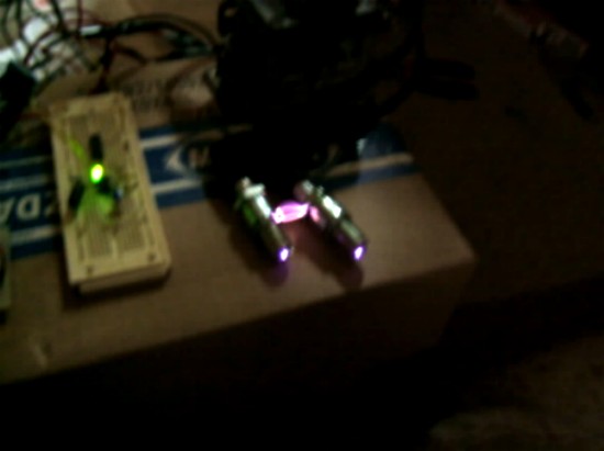
Here is a couple pics of the 2nd gen coil in action with the transistor trick circuit. The circuit itself is on the board with the red LED. The board with the green LED is a 555 timer circuit to simulate the input from the J-109. I ran the coil up to the equivalent of over 14,000 rpm. It performs flawlessly (get a bit warm though). At higher rpm, the arcs start to sound like a TIG welder. I found that at very low speeds the coil wouldn't fire well (below about 8 Hz [240 rpm]). This may be due to the duty cycle I was using (coil firing 34%-50% of the time). Although manually triggering the circuit (much less than 8 Hz) it works fine. Sorry the pics aren't too good. It was my friends camera and I haven't had much experience with it. I'll get some more pics when I install it in the car. Enjoy!
Kent
Around idle:
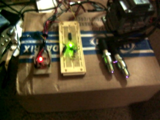
Probably near redline or so :
Kent
Around idle:
Probably near redline or so
:
06-04-05, 06:20 PM
#88
It works! :)
I received the igniters from jayroc yesterday. I really appreciate him donating to the cause. I installed the working first gen igniters from jayroc today along with the transistor trick circuit and 2nd gen coil. It works great. Definitely runs smoother and feels like it has a bit more power. I still need to install the 2nd gen plugs. I already have them on hand, just need to put them in.
I mounted the coil pack on the strut tower. However the AC compressor is in the way, so I had to disconnect the AC belt and move the compessor more towards the engine. The combination of AC and PS really take up a lot of room on that side of the engine bay.
The base of the coil gets fairly warm. I am not sure how that compares to the 2nd gen coil in the FC. I imagine that it is the same. If it is hotter, I guess we will need to either limit the duty cycle somehow or do something to keep the coil cooler (heatsink, fan, etc.).
I am currently assembing circuits for jayroc and lovintha7. That way we will have a couple more people to test how this setup works.
My friend with the digital camera is gone this weekend. I'll see if we can take some pics of the setup on Monday.
Kent
06-04-05, 08:18 PM
#90
Lives on the Forum
That's awesome news man! I'm currently using the 2nd gen coil pack and it performs much better than stock. I can't imagine improving over that, but if you have managed to do it then I will certainly be interested in checking it out.
I still have the 2nd gen ignitor that I removed from the coil pack, but the building of the rest of the circuit sounds like it's way over my head. Let me know if you need another guinea pig, I'd be happy to pay for parts/time if you build the circuit for me.
Congrats on the successful completion. Also, you will probably see a nice improvement once you get those fc plugs in. I ran my system on the stock plugs for the first year and it ran great, but when I changed to fc plugs this spring the difference was noticeable....
06-04-05, 09:54 PM
#91
I don't know how it compares to the 1st gen igniter/2nd gen coil setup as I have never tried that setup before. Jeff20b said there was a large improvement in spark using the 2nd gen igniter. I know for sure that it completely blows away the spark output of the first gen coil/igniter combo. I want to take some pics of the spark output for comparision (FB plugs, FC plugs, and maybe coil wire to chassis) with both the 1st gen coil and the 2nd gen coil.
Kentetsu: The circuit is pretty straight forward, but I would be happy to build you one. I could probably build them for about $15 shipped or so (mounted in box, connectors, wire, etc.). The only thing that I am limited on is the connectors for the first gen igniter. I have a few spares (cannibalizing an old dash harness), but will need to find another source of these connectors if I build more than a couple of these circuits. We could just use female spade connectors, but it doesn't look as nice and there is a possibility of getting the wires crossed.
The only thing that bothers me is that the base of the coil gets pretty warm. It is probably within its normal design range, but I would like to know for sure. I would like to some how compare the temperature of this setup to that of the FC setup. I would hate to be in the middle of nowhere and have the leading igniter go on me just because it got too hot.
I will throw the FC plugs in tomorrow and see if there is any improvement.
Kent
06-05-05, 02:33 AM
#92
Lives on the Forum
You might be able to get one of the FC guys to get a temp on their coil pack if you post in their section... I never felt mine to see how warm it runs, but you say it only happens when modified eh?
Lemme know if you get any together for sale, I'd be happy to do some before/after photo comparisons of the spark I get. Maybe fuel mileage and smoothness of idle would also be good indicators... Good luck with it, I hope it works out!
Lemme know if you get any together for sale, I'd be happy to do some before/after photo comparisons of the spark I get. Maybe fuel mileage and smoothness of idle would also be good indicators... Good luck with it, I hope it works out!
06-05-05, 04:02 PM
#93
Well, the heat generated is from the igniter not from the coil itself. I imagine that yours is really cool. I know that the 2nd gen coil itself stays cool. Your heat would be from your leading igniter. The problem is it is a bit hard to tell on the first gen igniter because you don't know if the heat is due to the igniter or to the engine itself.
I'll ask some second gen guys to see how hot their coil packs get. An infared temp measurement would be nice. Even better would be if I could compare with one of the local 2nd gen guys and use the same measurement instrument for both. I just want to be sure that we are within normal operating conditions so that we don't burn out any igniters.
One of the nice things about the transistor trick circuit is it takes the load off of the 1st gen igniter. As a result the 1st gen igniter stays much cooler and should last even longer than normal.
If you would like a circuit to do some testing. Let me know and I'll put one together for you. I would be interested in seeing the spark difference between the regular 2GCDFIS vs. 2GCDFIS with the transistor trick.
Kent
06-07-05, 07:04 AM
#94
Lives on the Forum
I'm up for the testing man. I have a nice camera at my disposal too, so good pix are no issue. I love tweaking my car for any advantage, especially those low $$ mods (which is why I did the 2nd gen ignition in the first place).
I plan to make my intro to Autox'ing in 3 1/2 weeks and have some work to do on the car anyway. Plan on upgrading fuel pump, get a pressure regulator and gauge too. Brake rotors (drilled/slotted) too. Wish I could squeeze tires in there too, but my handling is not my weak area right now so.....
Lemme know if you can do paypal and I'll hook you up for time/effort/parts. This Friday is payday with lots of OT on it for parts and more parts so, WHOOOHOOOO!!!
06-07-05, 12:46 PM
#95
Kentetsu: Sure thing. I'd be happy to build a circuit for you. I'll add you to the list. I'll send you a pm later with details.
Well, I haven't got much input from the 2nd gen forum. So I don't know if the temps are normal or not. Roger (renns) had some testing info listed on that MSEFI link that he posted. His testing indicated that the 2nd gen igniter goes into current limiting mode after approx. 1.6 ms or so (at 2000rpm). Mike Robert on there was running about a 3 ms pulse width to a HEI setup with minimal heating. We could add something to limit the pulse width. I think that right now the pulse width is too high and we are running with the igniter in current limiting mode for too long of a period (creating excess heat). We could fix his by adding a nonretriggerable monostable in between the two transistors. These can be triggered on either the leading or trailing edge of the pulse and produce an output pulse that is based on a RC time constant (independent of incoming pulse with). This way we can use a fixed pulse width (say 2ms or whatever) for all rpm values. What do you guys think? Jeff20b? Renns? Do you guys have any thoughts on this?
I am currently building the circuits for jayroc, lovintha7, and soon for Kentetsu. I just want to be sure that it is a good product before I sent it to you guys. I want to make sure that we aren't going to be killing igniters and possibly leaving us stranded somewhere because of excess heating of the igniter. I'll see if I can put the fixed pulse width circuit together tonight and do some bench testing. I'll let you guys know how it goes. Any input is appreciated.
Kent
06-07-05, 12:47 PM
#96
Rexy so sexy...
Join Date: May 2004
Location: midwest
Posts: 123
Likes: 0
Received 0 Likes
on
0 Posts
Could someone post up a list of the specific components used in this circuit? I'd like to build one but I need to know the proper tolerances on things, like the resistors. Looks like fun!
06-07-05, 01:16 PM
#97
Originally Posted by devitek
Could someone post up a list of the specific components used in this circuit? I'd like to build one but I need to know the proper tolerances on things, like the resistors. Looks like fun!
The tolerances for this portion don't really matter. I used standard 5% 1/4W resistors. The transistors are not real critical either. Any general purpose NPN transistor will work (2N2222A, 2N3904, 2N5401, etc.) The only thing I did a little different is I changed the pull-up resistor (near the LED) to 470 ohm instead of 1k. It doesn't really matter, but I did that to get the output pulse voltage a bit higher.
As I mentioned, this setup makes a very strong spark, but is creating a fair amount of heating of the 2nd gen igniter. I am going to try to limit the pulse width to try to reduce the heating but maintain the strong spark.
Last edited by gsl-se addict; 06-07-05 at 01:21 PM.
06-07-05, 01:35 PM
#98
Rexy so sexy...
Join Date: May 2004
Location: midwest
Posts: 123
Likes: 0
Received 0 Likes
on
0 Posts
I see. That answers the majority of the questions I had for components. As far as the heating, do we yet know how much? Does it burn flesh? Considering how hot things usually get under the hood (especially in the summer), is it really warm enough for concern?
06-07-05, 01:46 PM
#99
It gets hot enough to where if you held your finger on the back of the coil for more than 20 or 30 seconds, you might get a mild burn. I am currently the only one running this setup as far as I know. Jeff20b on the first post of this thread mentioned that the base of the coil got pretty hot during his bench testing as well. As I said, I don't know if it is normal. I have basically got no input from the second gen guys. There are a couple 2nd gen guys that I could ask locally that would probably help me out on this though. I'll see if limiting the pulse width helps the situation. If it does, I'll add the additional portion to the circuit. If not, we can safely say that it is normal for the igniter to run that hot.
06-07-05, 02:02 PM
#100
Rexy so sexy...
Join Date: May 2004
Location: midwest
Posts: 123
Likes: 0
Received 0 Likes
on
0 Posts
If I can get ahold of the 2nd gen stuff, I'll give this a test run. Might be a little while before I can do it, maybe a week or two, but I'll test things out gladly. First things first, I'm taking out my Weber 45 and putting in a rebuilt Nikki this week to get rid of all kinds of problems, after which we'll give this a spin.