RE-Speed steering kit! It's here!
 12-30-07, 08:57 AM
#76
I contacted Respeed regarding a RHD kit for Ozzy RX7s and all i got back was Id have to source my own RHD rack and that was it.
I also inquired about the "Specs" for the supplied kit LHD Mustang rack so i could source a similar spec RHD rack here in OZ, but i got nothing back! Mustangs are a luxury import here and not common.
I Guess they just dont need the business? its a shame as they would sell really well here if a suitable RHD rack was available.
 12-30-07, 09:02 AM
#77
Well id be interested in working with Respeed in developing a suitable RHD setup.. It would do well in Australia! Im not having a go at Respeed but there is a big market here and they would eat it up if it was available.
12-30-07, 10:34 AM
#78

I am sorry if you feel our response was less than adequate. I have personally answered 75+ emails pertaining to the same thing, a RHD kit. We are not apposed to working on a kit but we do not have the resources here to:
find a suitable rack that is readily available on your side of the pond.
A RHD chassis to develop with.
Knowledge of all the small changes from your steering column verses ours.
We looked into the special Flaming River rack that can be built in RHD spec. It retails for $700+ US. Just seems way out of the market pricing.
We have shipped a rack kit over there. The customer is developing it himself. He may send back data on his rack choice and needed changes.
As far as the rack specs, you are looking for a front steer, with inner toe rod pivots at approximately 20-25". Then you must confirm toe rod threads will be suitable to adapt to the stock outer tie rods. Confirm the steering shaft input spline pitch and find a suitable u-joint to interface it.
Then, dis-assemble the inner steering shaft and develop a new lower section. Bush the inner and outer steering shafts. Support the lower outer steering shaft. Connect the lower steering shaft to the steering rack input shaft u-joint, making sure to clear all the right hand side parts.
We are probably one of the only US Mazda after market companies left that jump through hoops to get product over the pond without huge shipping charges. We do not though out potential business, we just simply can not develop the RHD kit without much needed help from over there.
-billy
 12-30-07, 10:59 AM
#80
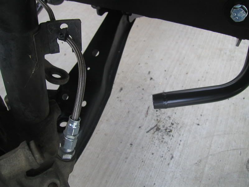
I was kind of hoping something would be made to replace those tension rod brakcets too, they are big, heavy, rusty and just un-needed. Since no such things exists right now I ended up cutting all the extra crap off mine, leaving a more or less flat piece that will bolt to the body and hold the sway bar on. I'll post pics of what I did if anyone cares. I also sandblasted them when done, came out pretty good.
I would definetely want to see just post it here since it's related. I kinda look at stuff like this as a quest that we are all on together anyways.
12-30-07, 11:15 AM
#81
Are my eyes decieving me of are the bolts for the two lower control arms lined up directly with each other. Meaning that the lca and rlca bolts could be removed and a shaft could be put straight through both brackets? Just one more idea for the mounts. It would negate the adjustable pivot point deal though without multiple mount positions. I was thinking chromoly rod then threaded on each end. Knock it through and there's your base from which to build on. Just one more option I'll be looking at when I get to that point. Let me know what you think. I guess a good question is how much weight do you think the rear brackets can hold. I imaginge the whole weight of the motor plus much more and they wouldn't even be holding all the weight anyways. Let me know what you thoughts are.
These Ideas make me loose sleep.......
12-30-07, 07:48 PM
#82
I am sorry if you feel our response was less than adequate. I have personally answered 75+ emails pertaining to the same thing, a RHD kit. We are not apposed to working on a kit but we do not have the resources here to:
find a suitable rack that is readily available on your side of the pond.
A RHD chassis to develop with.
Knowledge of all the small changes from your steering column verses ours.
We looked into the special Flaming River rack that can be built in RHD spec. It retails for $700+ US. Just seems way out of the market pricing.
We have shipped a rack kit over there. The customer is developing it himself. He may send back data on his rack choice and needed changes.
As far as the rack specs, you are looking for a front steer, with inner toe rod pivots at approximately 20-25". Then you must confirm toe rod threads will be suitable to adapt to the stock outer tie rods. Confirm the steering shaft input spline pitch and find a suitable u-joint to interface it.
Then, dis-assemble the inner steering shaft and develop a new lower section. Bush the inner and outer steering shafts. Support the lower outer steering shaft. Connect the lower steering shaft to the steering rack input shaft u-joint, making sure to clear all the right hand side parts.
We are probably one of the only US Mazda after market companies left that jump through hoops to get product over the pond without huge shipping charges. We do not though out potential business, we just simply can not develop the RHD kit without much needed help from over there.
-billy
I appreciate your distance realted issues with deveolpment of the RHD kit. Hopefully whoever bought your kit here can resolve it. ill cruise around the Ozzy forum and see if anyone has had any luck.
Cheers matt.

 01-02-08, 07:56 PM
#86
Sorry no updates. I was hoping to be all finished before I go to busy with other peoples stuff. aka customers stuff. It will be a couple weeks at the most I'll be caught up and het this fiished for you guys. Not mention the engine. Actually from this point though there is only the need for a bit of measuring and the tie rods being put on and your done. Just get it aligned. I will try to get you guys some pics of the "tilt" poart of the steering column when I modify it.
See you guys in a few days when I have time for myself again.
Hang tight!
to be continued..........
See you guys in a few days when I have time for myself again.
Hang tight!
to be continued..........

 01-25-08, 10:23 PM
#91
Alright ran into a bit of a problem with the transmission choice. I think I got it figured out now. Going to have to do a mini write up for this one.
First of all I have a GSL-SE trans, a S5 NA Trans, and 2 84-85 12a trans
Let me break it down:
Keeping in mind I will be running a stock ECU and bone stock S5 engine
12A trans is a no go since they both have minor problems and I don't want to deal with them. Also they don't have the correct part for the 5th gear switch in them as far as I can tell. The shift rod for the 5th and reverse is a bit different. So no 12A trans.
Next is the GSL-SE trans a perfect canidate. Obviously. It has all the nessecary parts and needs no modification. It does however have approx. 180,000 miles on it and looks to have seen better days. It works fine but it is old. Probably not the best trans to use when your adding more power. Just from the perspective of it's old. Also if I don't use it my friends car can be put together with it and all he will need is a coiuple parts and his seven is functional again. Plus his car is a GSL-SE.
Then there's the S5 trans. It has 91,000 miles on it and is in excellent shape. Now comes the issue with using it. At first for some reason the regular FB driveshaft wouldn't slide it. I don't know why and I thought. OK so I use the SE trans because I can't even put the driveshaft in. That's common sense. Today I went out to the garage and dropped the driveshaft right in. I felt stupid as a couple people were saying it fits fine. OK so that's great! a GSL or a GSL-SE driveshaft fits a NA S5 trans just fine. Now the problem is that the shifter housing is a bit too far back. I don't want to cut my chassis so I figured I'd do the extension housing swap with one of my 12A trans and I'm golden. HA! Don't think so the weird giant counterweight on the mainshaft of an S5 doesn't clear the inside of the 12A trans. CRAP! So I looked at it to see how much material would have to be removed. The short answer is too much!. I don't feel comfortable with the wall of my trans being so thin. So now what. I was thinking so I guess I'm back to the SE trans again. Crap I don't want to use it if my friend needs it. Then I start looking at the mount of the S5 trans and figured out a way to make a hybrid between the top half of the S5 trans mount and the bracket from the FB that mounts the trans to the car. With that decioded and out of the way now all I have to do is swap the shift rod and shifter housing from the 12A and I'm good again.
This leads to the following:
Stock S5 NA trans
Take of the extension housing
Change the shifter housing and shift rod
Put the extension housing back on with new sealant
put the mount on
and now the trans fits like a gsl-se trans but with a weirder looking mount.
I'll put up pics and a description of what I've done so you guys can see what the hell I'm talking about since it seems I'm not explaining it that well.
Stay tuned! <pun intended
01-26-08, 07:21 PM
#92
Here's the big counter weight in the S5 NA trans

Pics of the misalignment of the 12A housing


shift rod comparison 12A on bottom S5 on top

Shifter housing comparison 12A on top S5 on bottom

Put stuff back together


S5 on the fleft and the GSL-SE on the right

closer of the SE mount

closer of the new S5 mount

Above view with bell housings lined up

Tried to get a side view but It didn't come out that well. Trust me it's within three mm or so.

Soryy everything wasn't cleaned especially the mount and you can see I didn't even tighten the two side bolts on the mount yet just the big one in the middle. The rubber looking thing is actually a poly mount left over from my re-speed steering kit. You could substitute anything you want. I'll put up some more pics asap. Feel free to ask any questions if something is unclear I just didn't have much time to post this.
Pics of the misalignment of the 12A housing
shift rod comparison 12A on bottom S5 on top
Shifter housing comparison 12A on top S5 on bottom
Put stuff back together
S5 on the fleft and the GSL-SE on the right
closer of the SE mount
closer of the new S5 mount
Above view with bell housings lined up
Tried to get a side view but It didn't come out that well. Trust me it's within three mm or so.
Soryy everything wasn't cleaned especially the mount and you can see I didn't even tighten the two side bolts on the mount yet just the big one in the middle. The rubber looking thing is actually a poly mount left over from my re-speed steering kit. You could substitute anything you want. I'll put up some more pics asap. Feel free to ask any questions if something is unclear I just didn't have much time to post this.
01-28-08, 04:27 PM
#93
Alright here's the details of the engine mount I made since my other post is kinda vague:
First I used a die grinder to chop off the weld on the top of the stock bolt on the S5 mount. Here is it after grinding it down as flat as I could get it.

Here's a pic of the stock S5 mount bracket with the bolt I took out of it

Next I drilled a hole large enough for a 17mm bolt to pass through in the center of the stock FB bracket. Well it's mostly in the center it's a bit off but doesn't matter that much

A pic of the piece of poly from the re-speed kit that I used with the extra holes drilled in it.

One of it cut to size so that the part I need is the only part left. I used a razor blade and a hammer to chop it off with. The cut could have been a bit straighter but it doesn't really matter to me. If it was a customers car I would have spent the extra time but I wasn't too worried about myself.

Here's a picture of all the parts involved

A picture from the side with the 17mm bolt pushed through. This bolt will be the bolt actually holding the whole thing together were as I'm only using the two 12mm bolts to keep it from twisting.

A picture from the bottom with it all snugged up

A picture from the top with everything kinda snugged up

Now I just need to go to the store and buy some black paint to make it all pretty again then bolt it on and it's ready to go. It as you can see is very easy to do and like I said you can substitute a piece of rubber or a metal spacer or whatever you like to replace the poly bushing. One thing to notice here is that since the top part is not isolated from the bottom by just rubber like stock there will be a bit more vibration transmitted to the chassis and some people may not like this much. I could care less since my engien mounts are very stiff as well. The rubber in the bracket ends where the bolts pass through to the chassis will provide the movement and a bit more dampening as well.
On a seperate note I'm still waiting for my welder to have time to do the engine mounts. So hopefully soon so I can get this thing finished and running.
First I used a die grinder to chop off the weld on the top of the stock bolt on the S5 mount. Here is it after grinding it down as flat as I could get it.
Here's a pic of the stock S5 mount bracket with the bolt I took out of it
Next I drilled a hole large enough for a 17mm bolt to pass through in the center of the stock FB bracket. Well it's mostly in the center it's a bit off but doesn't matter that much
A pic of the piece of poly from the re-speed kit that I used with the extra holes drilled in it.
One of it cut to size so that the part I need is the only part left. I used a razor blade and a hammer to chop it off with. The cut could have been a bit straighter but it doesn't really matter to me. If it was a customers car I would have spent the extra time but I wasn't too worried about myself.
Here's a picture of all the parts involved
A picture from the side with the 17mm bolt pushed through. This bolt will be the bolt actually holding the whole thing together were as I'm only using the two 12mm bolts to keep it from twisting.
A picture from the bottom with it all snugged up
A picture from the top with everything kinda snugged up
Now I just need to go to the store and buy some black paint to make it all pretty again then bolt it on and it's ready to go. It as you can see is very easy to do and like I said you can substitute a piece of rubber or a metal spacer or whatever you like to replace the poly bushing. One thing to notice here is that since the top part is not isolated from the bottom by just rubber like stock there will be a bit more vibration transmitted to the chassis and some people may not like this much. I could care less since my engien mounts are very stiff as well. The rubber in the bracket ends where the bolts pass through to the chassis will provide the movement and a bit more dampening as well.
On a seperate note I'm still waiting for my welder to have time to do the engine mounts. So hopefully soon so I can get this thing finished and running.
01-29-08, 08:24 AM
#94
Thats kinda what my trans mount looked like initially but I decided to make it more complicated  , once its all cleaned up I'll post some pics of it, came out pretty good.
What are you doing for engine mounts? I'm currently working on the center iron mounts for my 13bt, is that what you are doing or are you going the front cover route?
, once its all cleaned up I'll post some pics of it, came out pretty good.What are you doing for engine mounts? I'm currently working on the center iron mounts for my 13bt, is that what you are doing or are you going the front cover route?
01-29-08, 12:56 PM
#95
I personally don't like the front cover idea at all. I'll tell you why. The front cover is aluminium. It only has like 5 bolts holding it to the iron. It seems to me like it is destined to leak from the gasket. Also seems to me there are a lot of half stripped bolt holes in front covers. cast iron is stronger than aluminium hence the reason I want to mount it like an FC. Not to mention the motor is almost perfectly balanced as far as weight goes when you have the mounts in the middle. I also don't like having to sacrifice another motor just to make one motor or having too many weird one off parts. Like what happens if my front cover gets damaged after modifying it to fit the Fc motor. Then I have to start the whole ordeal again. Not to mention the Fc oil pan has a larger capactity. Engines like oil. The more oil it can hold the better. Meaning I can run the **** out of the motor for longer without heating the oil up more. Another point is I can just go to the junkyard get another motor. Drop it in. Not have to switch around a bunch of parts and do a bunch of unneccessary work. I'm also lazy so a bit of work on the front side of things equally hardly any work on the tail end of thigs is appealing to me. This is also the reason my car has no heat shields on the bottom. I don't like having to take them off everytime I want to get at something under there. Not to mention they are quite heavy.
Let's see that mount. And how much more complicated could you make it transam?
I wish my welder was in as much of a hurry as me. he's so busy it sucks I'm still waiting. Also on a side note I think I may get a Rtek for this junker when it's done. Just something to play with a bit and I know a couple guys that tune cars that can help me out. I just gotta see if they say to say away from it or not. It appears to have everything I'll need except the AFM removal which is still in the works.
Oh yeah my engine mounts are hockey pucks. I'm Canadian, what can I say!
01-29-08, 02:56 PM
#96
I agree with you. The center iron method has to be stronger, and making a SE front cover work with S5 elctronics requires too much custom work...
I'll get pics later, but basically for the trans mount I wanted to make use of the stock FB rubber mount with the S5 T2 trans. I had to notch the FB's trans crossmember and make some custom brackets so the FB rubber mount would attach to the T2 trans. I wanted to make it so the rubber mount works without being modified (in case it needs replacment someday)
Notching the crossmember could be avoided by putting large spacers on the studs that hold the crossmember to the body like others have done, but I wanted to do something different... I'll post pics of that, along with those sway bar brackets I never posted pics of yet later on.
01-29-08, 04:17 PM
#97
Another quick update:
Just put the clutch and trans on nothing special
Here's a picture of my one month old ACT clutch I'm using. Installed and ready to go

The brackets all painted up and ready for final assembly

Mount assembled

Transmission close to it's house

Couple of the transmission and starter assembled to the motor


Now I'm REALLY just waiting for my welder to be available. Once the mounts are made then a few hoses, some wiring, and all the rest of the odds and ends that can't be done till the motor is installed. Like the radiator and stock airbox.
Just put the clutch and trans on nothing special
Here's a picture of my one month old ACT clutch I'm using. Installed and ready to go
The brackets all painted up and ready for final assembly
Mount assembled
Transmission close to it's house
Couple of the transmission and starter assembled to the motor
Now I'm REALLY just waiting for my welder to be available. Once the mounts are made then a few hoses, some wiring, and all the rest of the odds and ends that can't be done till the motor is installed. Like the radiator and stock airbox.
02-14-08, 01:56 PM
#99
OK sorry guys for the HUGE delay in posting more on what's going on. So the car is finally assembled steering rack wise anyways still waiting a bit longer on the engine mounts being made. Here's some pics of the tie rods:
A pic of the passenger side with the suspension at full droop and the steering arm at full droop.

A similar picture on the driver's side

A close up of the driver's side bolted up. There is no cotter pin because nothing is ready to drive yet and we may need to disassemble some parts while making the motor mounts.

One showing the ground clearance of the rack. There is obviously no clearance issue.

A zoomed out pic of the driver's side. Yes the sway bar is not connected I know. I'm trying to decide what to do with it still. There's no clearance issue I just need to decide poly bushings or the G-force engineering modification for anti-jacking of the suspension. ahhhh! decisions decisions.

On an extra note I'll be basing the motor mounts of of banzai racing's FC polyurethane mounts since stock mounts suck and the urethane ones are according to banzai exactly the same height as the factory ones. So when it's all said and done the mount kit can be used by anyone using all factory parts or they can buy the urethane mounts and never have to replace them again.
Keep watching I'm almost there. And the mounts should be made in the next couple of weeks here according to my welder he just needs to finish up another project and we're on to mine.
A pic of the passenger side with the suspension at full droop and the steering arm at full droop.
A similar picture on the driver's side
A close up of the driver's side bolted up. There is no cotter pin because nothing is ready to drive yet and we may need to disassemble some parts while making the motor mounts.
One showing the ground clearance of the rack. There is obviously no clearance issue.
A zoomed out pic of the driver's side. Yes the sway bar is not connected I know. I'm trying to decide what to do with it still. There's no clearance issue I just need to decide poly bushings or the G-force engineering modification for anti-jacking of the suspension. ahhhh! decisions decisions.
On an extra note I'll be basing the motor mounts of of banzai racing's FC polyurethane mounts since stock mounts suck and the urethane ones are according to banzai exactly the same height as the factory ones. So when it's all said and done the mount kit can be used by anyone using all factory parts or they can buy the urethane mounts and never have to replace them again.
Keep watching I'm almost there. And the mounts should be made in the next couple of weeks here according to my welder he just needs to finish up another project and we're on to mine.
Last edited by Skidtron; 02-14-08 at 01:57 PM. Reason: forgot a picture