
installing dizzy

Thread Starter
Rotary Freak
Joined: Sep 2004
Posts: 1,901
Likes: 0
From: Kitchener, Ont. Canada
installing dizzy
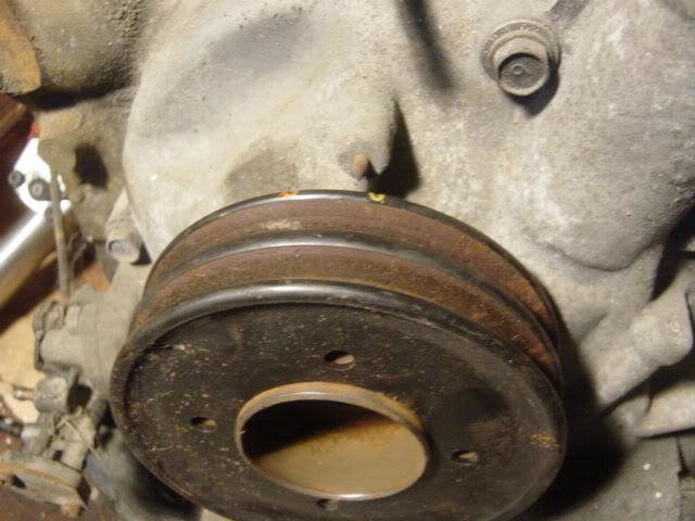
im having problems trying to figure out how to install this distributor into my 85 gsl. the engine i want to install it on currently has no distributor at all....and the pulleys clearly do not have any yellow mark, or any notches like its suposed to have...the pulley is a little rusty, and i just can't make out any notches
the distributor is currently mounted on my old motor, its loosened, but i havn't pulled it out yet because i want to make sure it comes out and goes in the other engine the proper way, but again the problem resides in teh pulleys onthat motor being rusted, and i cdan't make out any notches or marks
is there any other way to make sure i install this thing the proper way?
Thread Starter
Rotary Freak
Joined: Sep 2004
Posts: 1,901
Likes: 0
From: Kitchener, Ont. Canada
sounds like a good plan. these notches must be real tiny cuz i've looked real hard
and its the same with both engines. i can't see anything on either.
where exacdtly are the notches? i assume they are on the backside (the side facing the front cover) on the most outer edge of the pulley or am i missing something
and its the same with both engines. i can't see anything on either.
where exacdtly are the notches? i assume they are on the backside (the side facing the front cover) on the most outer edge of the pulley or am i missing something
Last edited by nick1; Feb 23, 2006 at 02:12 PM. Reason: forgot to mention

Senior Member
Joined: Mar 2005
Posts: 435
Likes: 0
From: PA
The notches on mine are VERY small - only visible on the rear flange of the pulley.
If I were to guess, I'd say the notch is actually a nick - about 1 mm wide. I had to use the timing light to find it.
If I were to guess, I'd say the notch is actually a nick - about 1 mm wide. I had to use the timing light to find it.
Wassup!!
Joined: Jul 2001
Posts: 1,081
Likes: 1
From: Longmont Co.
Originally Posted by nick1
sounds like a good plan. these notches must be real tiny cuz i've looked real hard
and its the same with both engines. i can't see anything on either.
where exacdtly are the notches? i assume they are on the backside (the side facing the front cover) on the most outer edge of the pulley or am i missing something
and its the same with both engines. i can't see anything on either.
where exacdtly are the notches? i assume they are on the backside (the side facing the front cover) on the most outer edge of the pulley or am i missing something
Originally Posted by capt murph
The notches on mine are VERY small - only visible on the rear flange of the pulley.
If I were to guess, I'd say the notch is actually a nick - about 1 mm wide. I had to use the timing light to find it.
If I were to guess, I'd say the notch is actually a nick - about 1 mm wide. I had to use the timing light to find it.
Trending Topics

Full Member
Joined: Oct 2005
Posts: 80
Likes: 0
From: Florida
Tdc
You can also remove the pulley from the concentric shaft, find out where the woodruff key (the keyway in the shaft) is. Slide the pulley back on marking the position of the keyway with the pulley( use a felt pin or scribe). Now rotate the pulley by hand until the keyway is at the 9 o'clock position. (9 o'clock is on the left side of the engine as you are facing it. Once you have done that, the position of the pulley tha tlines up with the pointer is TDC (0). You can figure about a quarter of an inch to the right of that mark is 10 degrees BTC and a quarter inch left is 10 degrees ATDC. This should get you in the ball park. scribe or file your notches on your pulley, makr them iwth the appropriate colored paint (Testors model paint works great, use a toothpick, as the grove should be very narrow). Now locate teh dimple on the dizzy and align it with the boss on the bottom of the dizzy housing. (do not confuse the spring pin with the dimple). Hold the rotor button so tha the dimple and boss do not rotate. Insert the dizzy, hand tighten the nut and start the engine, adjust the timing. Due to the possibilty of minor slop in the marks, you may have to micro tune it by ear. Good Luck. Also if you are not sure of exactly what you are doing, find a pulley that has the marks on it and install it. Later.
Thread Starter
Rotary Freak
Joined: Sep 2004
Posts: 1,901
Likes: 0
From: Kitchener, Ont. Canada
Originally Posted by mx-57
You can also remove the pulley from the concentric shaft, find out where the woodruff key (the keyway in the shaft) is. Slide the pulley back on marking the position of the keyway with the pulley( use a felt pin or scribe). Now rotate the pulley by hand until the keyway is at the 9 o'clock position. (9 o'clock is on the left side of the engine as you are facing it. Once you have done that, the position of the pulley tha tlines up with the pointer is TDC (0). You can figure about a quarter of an inch to the right of that mark is 10 degrees BTC and a quarter inch left is 10 degrees ATDC. This should get you in the ball park. scribe or file your notches on your pulley, makr them iwth the appropriate colored paint (Testors model paint works great, use a toothpick, as the grove should be very narrow). Now locate teh dimple on the dizzy and align it with the boss on the bottom of the dizzy housing. (do not confuse the spring pin with the dimple). Hold the rotor button so tha the dimple and boss do not rotate. Insert the dizzy, hand tighten the nut and start the engine, adjust the timing. Due to the possibilty of minor slop in the marks, you may have to micro tune it by ear. Good Luck. Also if you are not sure of exactly what you are doing, find a pulley that has the marks on it and install it. Later.
WOW! thanks for the reply....so what you are basically saying is that the pulley only goes on one way, and the dimple thingy on the pulley only allowing it to go on one way is at 9:00 for TDC
that helps alot....nop how do i remove this pulley. lol
Pulleys on the 2nd gens only fit one way, the 1st gens can be clocked in 4 different positions, 3 of which are wrong. You cannot see the e-shaft keyway with out removing the front bolt, DO NOT DO THAT. You stand a very good chanch of having one of the thrust bearings falling and it will throw the endplay out on the motor.
Do a search under Wacky's name and timing or finding tdc. The pics he posted make fimding tdc self explanatory.
Do a search under Wacky's name and timing or finding tdc. The pics he posted make fimding tdc self explanatory.
Thread Starter
Rotary Freak
Joined: Sep 2004
Posts: 1,901
Likes: 0
From: Kitchener, Ont. Canada
thank you trochoid
for the most part, these forums are a goldmine of information....but from time to time you may get some info from somone who really only means well, but their info may be a little off, probably just because they have obtained the info from sources that are not 100%.
now when i read the post by mx-57, i thought...thank god..someone who knows exactly what they are talking about. this seems easy....im gunna go ahead and do what he says, and then someone else jumps into the thread and advises against it....it can be frustrating. everyone means well, but sometimes when you're dealiing with these problems that are actually quite complex, there are many ways, right, wrong, half assed, etc....it can be hard
im doing a search under wacky and TDC, and hopefully i can get this thing figured out for sure. i really need to get this car on the road.
thanks to all who contributed information. im way further ahead than i was, and that's a good thing.
nick
I searched for the pics but haven't been able to find them. My search skills are kind of lame some days and I am not 100% sure it was Wacky that posted them.
Basicly, you take off the flywheel inspection cover on the passenger side of the engine and set the flywheel so the built in counter weight's inside edge is straight up and down. Most of the engines I have worked on, you cannot see the timing nicks due to peeling paint and rust. I have been able to find them by feel occasionally or wire brushing/sanding the pulley.
If all else fails, mark the orientation of the pulley and remove it, (4 10mm head bolts), then you should be able to clean it up and find the marks. Before re-install, mark both nicks with different colors. If you have a female counterpart, borrow 2 colors of nail polish and paint the nicks.
Finally found it, this should help you out. https://www.rx7club.com/1st-generation-specific-1979-1985-18/main-pully-timing-498940/
Thread Starter
Rotary Freak
Joined: Sep 2004
Posts: 1,901
Likes: 0
From: Kitchener, Ont. Canada
Originally Posted by trochoid
I searched for the pics but haven't been able to find them. My search skills are kind of lame some days and I am not 100% sure it was Wacky that posted them.
Basicly, you take off the flywheel inspection cover on the passenger side of the engine and set the flywheel so the built in counter weight's inside edge is straight up and down. Most of the engines I have worked on, you cannot see the timing nicks due to peeling paint and rust. I have been able to find them by feel occasionally or wire brushing/sanding the pulley.
If all else fails, mark the orientation of the pulley and remove it, (4 10mm head bolts), then you should be able to clean it up and find the marks. Before re-install, mark both nicks with different colors. If you have a female counterpart, borrow 2 colors of nail polish and paint the nicks.
Basicly, you take off the flywheel inspection cover on the passenger side of the engine and set the flywheel so the built in counter weight's inside edge is straight up and down. Most of the engines I have worked on, you cannot see the timing nicks due to peeling paint and rust. I have been able to find them by feel occasionally or wire brushing/sanding the pulley.
If all else fails, mark the orientation of the pulley and remove it, (4 10mm head bolts), then you should be able to clean it up and find the marks. Before re-install, mark both nicks with different colors. If you have a female counterpart, borrow 2 colors of nail polish and paint the nicks.
i am going to try the flywheel thingl. the cover is all banged up anyways, so i should be able to see the counterweight hopefully.
i'll see what i can figure out, and post here with the results
nick
Sorry for the confusion. You can take off the pulley, but to see the keyway from the front, the e-shaft bolt needs to be removed. Removing the e-shaft bolt is the nono. The main pulley can be removed by taking out the 4 bolts, leaving the e-shaft bolt alone. Just be sure to mark the pulley before you take it off so it is clocked the same way when you reinstall it.
Hope that clears things up.
Hope that clears things up.

Thread
Thread Starter
Forum
Replies
Last Post
24seven_dada
3rd Generation Specific (1993-2002)
20
Nov 10, 2018 12:03 PM
Jeff20B
1st Generation Specific (1979-1985)
73
Sep 16, 2018 07:16 PM