How to tear down a 12A without a shop
 12-08-12, 12:43 PM
#101

Jeff, you've convinced me again, that 30 lb. flywheel has now been retired to my Rotary Museum, thanks. I've put out an ABB to the Atlanta area rotary community for an 81-82 flywheel to match my 81-82 counterweight and R5 rotors. I'm still confused about how that 81-82 counterweight came out of one of my FB tear downs though, since according to the flywheels they were all 83-85 12As.
Also, now that counterweights have become an issue, I've done a bit of searching (which I should have done before) and I see that Jeff, Mike and bumpstart have had this discussion a few times already, so my apologies for not noticing earlier, although it is complicated enough to deserve revisiting once in awhile. Thanks bumpstart for those links and to all you guys for sharing your knowledge.
It makes sense that that thermal reactor tube is locking the exhaust sleeve into place, I just can't see any other way it could be held in there unless it's actually welded in place. What bothered me when I was trying to knock out the sleeve from the inside with that wide punch was the darn sleeves wouldn't budge even a tiny bit. It seems they would have moved at least a tiny bit if something was just locking them in. I hope you can figure this out Jeff, it would be nice to get those sleeves out of the way.
On the end play, I've never done that before but the concept and adjustment seems straightforward. I might even get lucky and have the right thrust spacers recovered from all the tear downs to have what I need. I did notice the end play on the R5 engine was ridiculous before I tore it down, you could move the pulley shaft in and out a good eighth of an inch, weird, I don't see how the engine could run that way.
Jeff, is the 225 mm clutch and pressure plate the same as came out of the 84/85 12A FB's? I have several of these in good condition, one almost new that I installed in my 84 GSL only a few months before it was retired. I was hoping to use that set.
I'm going to go bang on those exhaust port sleeves some more, who knows, maybe they'll cooperate this time.
 12-08-12, 10:48 PM
#102
Gosh all this talk about the exhaust inserts makes me want to bang them out on my spare housings. Then get a dyno/decible reading of my current setup... Then put the spare housings in and dyno/decible readout the "no insert" housings.
EDIT: Ray take your housings to a muffler shop and ask them to weld them out with a MIG. The housings are Al and the inserts are steel. The steel will melt away before the housing does. Thats why my redneck weld table is Al.
EDIT: Ray take your housings to a muffler shop and ask them to weld them out with a MIG. The housings are Al and the inserts are steel. The steel will melt away before the housing does. Thats why my redneck weld table is Al.
Last edited by Qingdao; 12-08-12 at 10:50 PM.
12-09-12, 12:42 AM
#103
Ray, your 81-82 from CW probably came from an engine that had an incorrect flywheel on it. I've seen that before where someone stuck an S4 NA flywheel on a GSL-SE. It wore the stat bearings way deep into the copper due to the wrong balance. It had all stock motor mounts so you couldn't feel any vibrations though.
Ray, ahving dealt with the really strange JC Cosmo sleeves, I can assure you the thermal reactor tubes aren't welded to the inner or outer sleeves. If they were, how were they installed? From my meager understanding of the way Mazda makes mechanical connections, such as roll pins etc, I'd bet the thermal reactor tubes will come out after the roll pin is removed. They will slide right on down and out. They should; it's the only thing that makes sense. Then the other two roll pins (on each side of the housing) can be removed and this will allow the dual sleeve unit to come out. Once out, it should become aparant how they're attatched together. Now here is where you may be right - I think they might actually be welded togther in front right next to the exhaust port. It would make for a smoother path for incoming exhaust and physically lock them together. It should be easy enough to take to a bench grinder. It's inconel but an aluminum oxide or garnet grinding wheel will make short work of it.
Yep, lots of end play in R5 engines.
Yep, any 83-85 disc and pressure plate will fit an 81-82 friction surface. You will find it is 225mm across, but just barely. You'll need to get the bolt kit from Mazdatrix that contains aluminum spacers. You also need to make sure the rivits of the pressure plate won't bottom out on the flywheel. Some years of pressure plates have different designs than others.
Look here for some pictures. https://www.rx7club.com/1st-generati...3/#post7488951
The following users liked this post:
THRILCKR (06-07-21)
12-09-12, 04:38 PM
#105
Thanks Sgt., pm sent!
Jeff that 81-82 counterweight must have gotten there from an earlier not-quite-right rebuild, like you say. A gift from the Rotary Gods, perhaps?
Thanks for that clutch link!
On the exhaust inserts, I've come to the conclusion the Rotary Gods want them to be there. You don't want to mess with fate.
Does anybody know how balancing the rotating assembly is done? This sounds like a cool thing to be able to do.
 12-10-12, 12:07 AM
#107
Don't worry about balancing. The R5 rotors are factory matched. They are within the 50 gram difference tolerance. The R5 I built for the blue car was 12 grams apart. when your rotors weigh over 5000 grams each, 12 grams is nothing. Other factory rotor sets have been 11 and 10 grams apart - I was able to weigh them since I got a digital scale a while back.
Balancing comes in two forms. Static and dynamic. Static just means you drill material from the rotors until they weigh the same. In your case it is not necessary. Dynamic is big bucks and not necessary for your stock engine. Any plans to peripheral port? Nope. Besides I'd opt for the lighter 83-85 rotors anyway, not those heavy R5/SA type, and I'd probably pay to have them dynamically balanced rather than trust a static balance job. Hey, fellow rotorheads, did I get my terms right?
Balancing comes in two forms. Static and dynamic. Static just means you drill material from the rotors until they weigh the same. In your case it is not necessary. Dynamic is big bucks and not necessary for your stock engine. Any plans to peripheral port? Nope. Besides I'd opt for the lighter 83-85 rotors anyway, not those heavy R5/SA type, and I'd probably pay to have them dynamically balanced rather than trust a static balance job. Hey, fellow rotorheads, did I get my terms right?
12-10-12, 02:17 PM
#108
Thanks Jeff, static balancing sounds like something I can do with the scales at work, so why not check it at least?
And dynamic balancing means expensive shop time, which I'm trying to avoid with this "educational" rebuild, so I won't.
I do have two good sets of 83-85 rotors with their respective rotating assemblies, but I'm hoping to save these for my future projects and use the slightly heavier R5 rotors and assembly, which are in great condition (and have prefitted side seals) for the current project. The only significant downside is the heavy 30 lb. flywheel and counterweight of the R5 system, which I'm hoping to replace with the 81-82 flywheel according to your early suggestion.
The Sgt. has just what I need and it sounds like he's willing to make a generous donation to the project. Looks like Lucy has yet another benefactor!
12-10-12, 03:04 PM
#109
Cool. Sounds like you're "getting it" now. 
Yes, weigh your R5 rotors and tell me what the difference is. It shouldn't be more than 15 grams but to get a really accurate weight, they need to be 100% clean. No carbon. No oil. No seals. No springs. Clean and dry (watch out for surface rust if you handle them too much). Try to leave the factory cadmium plating on the rotors so don't use sandpaper or other harsh cleaners. I find a fine wire wheel works best.
Yes, weigh your R5 rotors and tell me what the difference is. It shouldn't be more than 15 grams but to get a really accurate weight, they need to be 100% clean. No carbon. No oil. No seals. No springs. Clean and dry (watch out for surface rust if you handle them too much). Try to leave the factory cadmium plating on the rotors so don't use sandpaper or other harsh cleaners. I find a fine wire wheel works best.
12-10-12, 07:21 PM
#111
Moderator
iTrader: (3)
Join Date: Mar 2001
Location: https://www2.mazda.com/en/100th/
Posts: 30,829
Received 2,597 Likes
on
1,845 Posts
i did buy new rotors, a new eshaft, i think the rear counterweight was new too (basically i reused a distributor gear and the tension bolts). the only thing need to balance the whole thing was some metal was added to the rear CW.
this tells us that the dynamic balance is fine. my pair of rotors must have been really close, but i do agree that under 8000rpm within 50g is totally fine.
when you weigh yours, it'll be interesting to see how close they are, and B i bet you could file a couple grams off the heavy one in a non critical spot and get it closer
12-11-12, 11:51 PM
#112
OK, Sgt. just sent a note and said he's mailing his 82 flywheel and counterweight for installation in Lucy, so now I don't need to warp my brain anymore trying to figure out what balances with what and why. Thanks Sgt!
I did weigh my counterweights on the lab scale today and they all had different weights. But the rotors were just a bit too much for the lab scale.
So I decided to purchase a postal scale from amazon, it's a real nice one that weighs anything from a few ounces up to 75 lbs. $31 shipped.
No more guessing, I'll post up my static balancing data in about a week.
12-16-12, 01:16 PM
#113
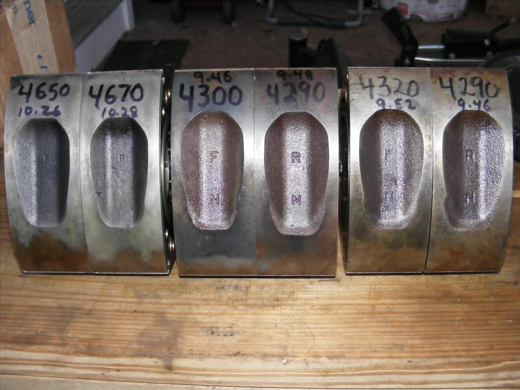
Sgt's 81-82 flywheel arrived, it's a beauty!
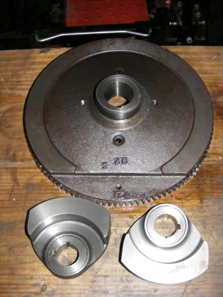
The counterweight on the left is the one Sgt sent and the one on the right came out of one of my 83-85 tear downs, as best I can tell.
Also, I got my postal scale from amazon so now I can weigh everything, notice the weights marked on the parts. It's a nice little scale for $31, weighs accurately from a couple grams up to 75 lb.
Note the 81-82 flywheel weighs just under 23 lbs., like it should, and the counterweights are about 1035 g each (2 lb, 4.5 oz).
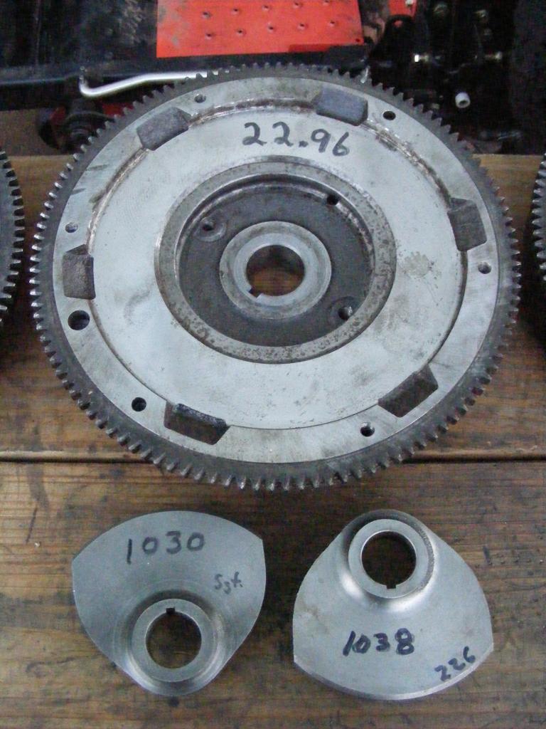
Here's the old R5 flywheel and counterweight, clunking in at just over 30 lbs. with a 1281 g counterweight (2 lb, 13 oz).
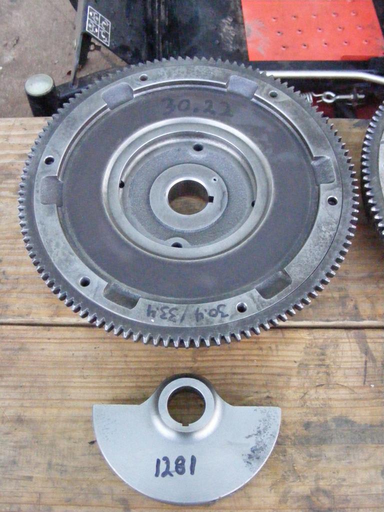
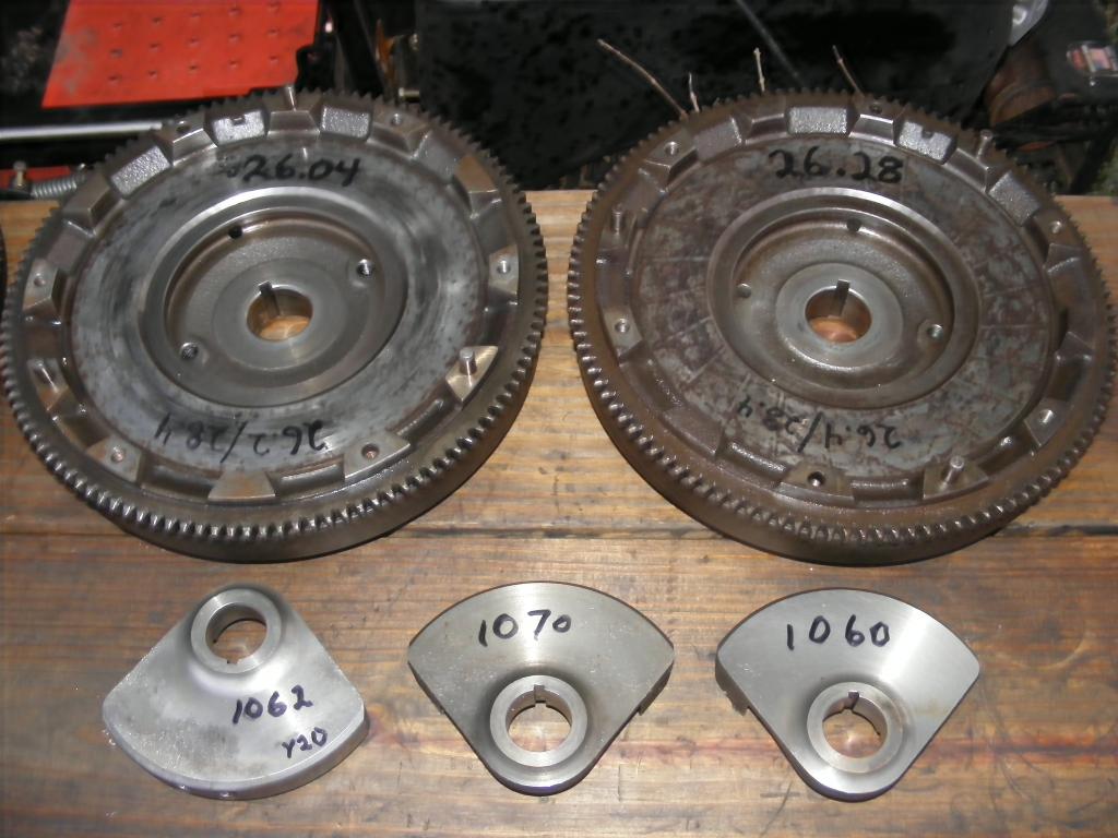
And here's a couple of 83-85 flywheels (a little over 26 lb. each) and some 83-85 counterweights, which weigh in at 1060-1070 g (2 lb., 5.6 oz).
And three sets of rotors, the R5's (on the left) weighing in at about 10.26 lb each and the lighter 83-85 rotors weighing around 9.5 lb. each
So I still like the 81-82 flywheel idea and that's what I'm going to do for the current rebuild, but I still can't figure something out and I have a bigger question.
Why is it you can't combine the later, lighter 83-85 FB rotors with the lighter 81-82 flywheel and front counterweight?
The front counterweight balances the flywheel, right?
And the weights of the rotors need to closely match each other to avoid harmonic imbalance between the rotor housings, right?
But if these two are independent of each other, why can't you use any year rotors with any year flywheel and counterweight?
The counterweight on the left is the one Sgt sent and the one on the right came out of one of my 83-85 tear downs, as best I can tell.
Also, I got my postal scale from amazon so now I can weigh everything, notice the weights marked on the parts. It's a nice little scale for $31, weighs accurately from a couple grams up to 75 lb.
Note the 81-82 flywheel weighs just under 23 lbs., like it should, and the counterweights are about 1035 g each (2 lb, 4.5 oz).
Here's the old R5 flywheel and counterweight, clunking in at just over 30 lbs. with a 1281 g counterweight (2 lb, 13 oz).
And here's a couple of 83-85 flywheels (a little over 26 lb. each) and some 83-85 counterweights, which weigh in at 1060-1070 g (2 lb., 5.6 oz).
And three sets of rotors, the R5's (on the left) weighing in at about 10.26 lb each and the lighter 83-85 rotors weighing around 9.5 lb. each
So I still like the 81-82 flywheel idea and that's what I'm going to do for the current rebuild, but I still can't figure something out and I have a bigger question.
Why is it you can't combine the later, lighter 83-85 FB rotors with the lighter 81-82 flywheel and front counterweight?
The front counterweight balances the flywheel, right?
And the weights of the rotors need to closely match each other to avoid harmonic imbalance between the rotor housings, right?
But if these two are independent of each other, why can't you use any year rotors with any year flywheel and counterweight?
12-16-12, 03:49 PM
#114
Moderator
iTrader: (3)
Join Date: Mar 2001
Location: https://www2.mazda.com/en/100th/
Posts: 30,829
Received 2,597 Likes
on
1,845 Posts
and at this time i'd like to turn it over to our correspondent in the field, Jeff20B....
seriously, i don't know, i sent my stuff to someone who does.
there is a chapter about it in Kenichi Yamamoto's book http://foxed.ca/rx7manual/manuals/RE...amoto-1981.pdf
section 3.42; Balance of inertia force, P26 in the book 31 in the PDF. notice the complex maths? i did!
seriously, i don't know, i sent my stuff to someone who does.
there is a chapter about it in Kenichi Yamamoto's book http://foxed.ca/rx7manual/manuals/RE...amoto-1981.pdf
section 3.42; Balance of inertia force, P26 in the book 31 in the PDF. notice the complex maths? i did!
12-16-12, 07:45 PM
#115
Ray, you can't use the 83-85 rotors with the 81-82 counterweight and flywheel. It leads to premature stationary bearing wear and can sometimes be felt as a vibration. In other words they were designed for a specific amount of rotor weight. If the rotors weigh more or less than the counterweights were intended to offset, it causes an imbalance when the shaft rotates which puts a heavier load on the bearings and gets into the copper faster. The bearings were designed to handle the entire weight of the rotating assembly including flywheel (yes even a 30 pound monster). However a lot of front stat gear bearing wear can occur from an alt belt tightened too much. You... do know that don't you? That a too tight belt can hurt your front bearing? Anyway something sorta similar happens when the wrong flywheel and counterweight are used, but instead of it only being forced in one direction, such as "up" in the case of an overtightened alt belt, what happens when there is a major imbalance in your engien is an eccentric movement of the shaft itself which increases exponetially as RPM increases, and forces probably tens to hundreds of pounds of force in rotating(eccentric) motion and eventually gives you a nice pretty copper surface all the way around usually both stat bearings. It also wears one small section of your shaft's stat bearing journals more than the rest, shoing where the eccentric-ness was most strong, giving them kind of an oblong shape instead of a perfectly round shape.
So then how do the counterweights work? And what is the point of them and all these silly numbers you see on your scale?
I'll just sum it up with this brief explnation as far as I understand it.
Front rotor:
The front counterweight balances half the front rotor's weight. The rear rotor balances the other half of the front rotor's weight.
Do you follow so far? Let's keep going.
Rear rotor:
The rear rotor is balanced half way by the front rotor and half by the flywheel.
I really hope that makes sense and I won't have to keep typing about it. Now with this brief education, can you tell me how a 20B is possible with three rotors and only two counterweights?
12-16-12, 10:49 PM
#116
Moderator
iTrader: (3)
Join Date: Mar 2001
Location: https://www2.mazda.com/en/100th/
Posts: 30,829
Received 2,597 Likes
on
1,845 Posts
 12-18-12, 03:14 PM
#118
The RX-8 version are better for an NA because they produce less friction. The FD (NF01) types are stronger and quite unnecessary on an NA. Also more expensive. But you know, get whatever gives you confidence. And yes both types work perfectly with 3mm apex seals without any modding required.
01-27-13, 02:29 PM
#119
I wouldn't call that NO plate an R5 plate even though it comes stock in some R5 models. I say this because other R5 models had an actual R5 intermediate plate with exact same port timing as your Y. These are the diamonds to look out for.
Look for an R5 or R on the intermediate plate. If you see R5 or R, it has tall runners and Y size primary ports. They make a perfect candidate for your engine. Of course your Y plate will do just fine.
I may have to use a Y plate in my 18 tension bolt R5 build if my R plate isn't available.
Look for an R5 or R on the intermediate plate. If you see R5 or R, it has tall runners and Y size primary ports. They make a perfect candidate for your engine. Of course your Y plate will do just fine.
I may have to use a Y plate in my 18 tension bolt R5 build if my R plate isn't available.
My first question is what's the difference between the "Y" plates and the "R5" plates? I just took apart the motor from my 79 and it has the "R5" plates front, middle, and back. The 80 donor motor I grabbed from the junkyard has a "Y" on the rear plate. Haven't gotten to taking it apart yet tho so I'm not sure what the front and mid plates are on that... But, what's the difference between "R5" and "Y"? Which is better?
Second, and this has to do with the seals, how do you keep them all separate? I mean, what is the labelling convention? I can think of a system for the apex seals, springs, and corner pieces, but how do you keep track of the side seals? I've taken my rotors out of the 79 engine, but I haven't taken any of the seals off yet to clean the rotors, because I don't want to mess up their placement if I can reuse any of them. Stupid question?
Thanks!
Keep up the good work Ray. Love this thread! Was looking for it forever and finally found it again.
01-27-13, 11:39 PM
#120
Moderator
iTrader: (3)
Join Date: Mar 2001
Location: https://www2.mazda.com/en/100th/
Posts: 30,829
Received 2,597 Likes
on
1,845 Posts
its actually really simple, there is a number stamped near each side seal groove, so you just need a box/safe place with a number that matches each seal
1,3,5 on one side of the rotor and 2,4,6 on the other
1,3,5 on one side of the rotor and 2,4,6 on the other
01-29-13, 11:08 AM
#121
I didn't know a tight alt belt could cause stationary gear wear.
However a lot of front stat gear bearing wear can occur from an alt belt tightened too much. You... do know that don't you? That a too tight belt can hurt your front bearing?
I didn't know a tight alt belt could cause stationary gear wear. Do you have to really lean on it when you adjust the belt or does even moderate over-tightening cause problems?
Wow, that's kind of a big issue and to only stumble on it buried in a sub thread is not good either.
I didn't know a tight alt belt could cause stationary gear wear. Do you have to really lean on it when you adjust the belt or does even moderate over-tightening cause problems?
Wow, that's kind of a big issue and to only stumble on it buried in a sub thread is not good either.
 02-21-13, 07:16 PM
#125
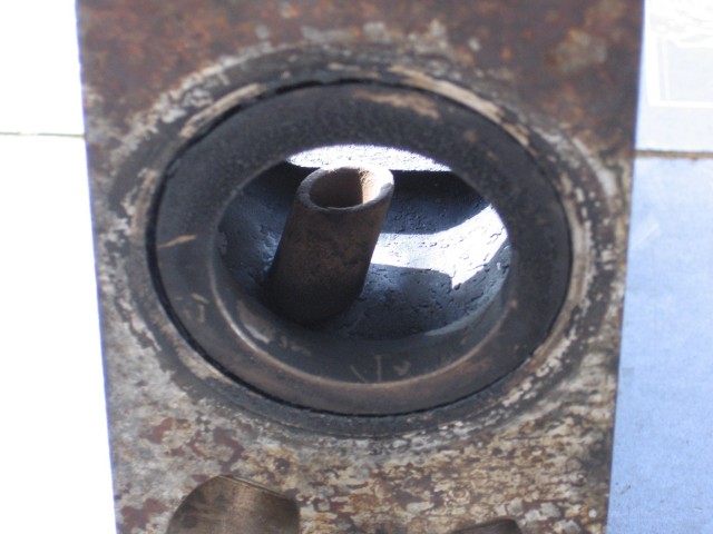
Update on Jeff's efforts with those exhaust port intrusions, they do come out after all:
The sleeves are done. One thing that made it easier is to use a small cutting disc. A dremel can get into the tighter areas but I managed with an air powered disc, and it was faster than a dremel would have been. The bench grinder was also used in combination.
Eventually the inner sleeve could be removed after the welds were weakened enough. A screwdriver seperated them. Then you lift the sleeve off the other sleeve.
A little cleanup with a dremel stone and a wire wheel finished the job.
An inspiration was deciding to swap sleeve locations. So the front sleeve is in the rear housing now. Why? Because of the gaping hole from the thermal reactor air injection tube. swapping sleeves covers over this hole really nicely so it's practically the same as any SA housing.
Another option is to fill in the air injection holes but again, an SA has these.
I chose to pull the roll pins from these too. The frist one came out like usual. The second one had the screw break off inside! This is due to the weird angle. I never ran into this problem with a regular sleeve roll pin. The anlge was too much and broke the screw.
So another option is to grind down the top of the tube. I've done this on later R5 housings that have the tube but no way to remove it.
stupid emissions tube, to be removed
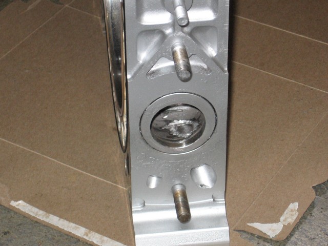
Emissions tubes removed (this works fine as proven on PercentSevenC's R5 13B with S5 turbo)
The sleeves are done. One thing that made it easier is to use a small cutting disc. A dremel can get into the tighter areas but I managed with an air powered disc, and it was faster than a dremel would have been. The bench grinder was also used in combination.
Eventually the inner sleeve could be removed after the welds were weakened enough. A screwdriver seperated them. Then you lift the sleeve off the other sleeve.
A little cleanup with a dremel stone and a wire wheel finished the job.
An inspiration was deciding to swap sleeve locations. So the front sleeve is in the rear housing now. Why? Because of the gaping hole from the thermal reactor air injection tube. swapping sleeves covers over this hole really nicely so it's practically the same as any SA housing.
Another option is to fill in the air injection holes but again, an SA has these.
I chose to pull the roll pins from these too. The frist one came out like usual. The second one had the screw break off inside! This is due to the weird angle. I never ran into this problem with a regular sleeve roll pin. The anlge was too much and broke the screw.
So another option is to grind down the top of the tube. I've done this on later R5 housings that have the tube but no way to remove it.
stupid emissions tube, to be removed
Emissions tubes removed (this works fine as proven on PercentSevenC's R5 13B with S5 turbo)