When you click on links to various merchants on this site and make a purchase, this can result in this site earning a commission. Affiliate programs and affiliations include, but are not limited to, the eBay Partner Network.
Ok, before I start, I know there is a thread in the archives that outlines how to do what I am going to tell you here. That thread is absolutely HORRIBLE. Showing how to wire a relay using a text diagram = epic fail and there is a general lack of information within that thread. Basically it didn't help at all. I never did figure out the relay wiring from that thread.
So, to begin, this "how to" is to explain the process to properly upgrade a 79-80 externally regulated alternator to a 81-88 internally regulated alternator while retaining proper function of your dash lights and choke ****, all without adding any extra wires. There are a few reasons one might want to do this. First one is obvious, regulator or alternator has failed and you can't locate a new/rebuilt one. There are loads of good 81-88 alternators out there for real cheap. Reason two, you need more electrical power to supply a more powerful stereo. 86-88 alternators can do this, along with the swap to a GM 105 amp alternator, both of which are internally regulated. Reason the third, internally regulated alternators tend to be more reliable (personal experience, others may refute this).
So, I might as well start off with a list of suggested tools and parts.
Parts:
-2 12V automotive relays of the 5 pin type
-14 and 18 gauge spade terminal connectors, insulated
-14 and 18 gauge butt connectors, non insulated (insulated ones can be substituted)
-18 gauge 1/4" crimp on ring terminals
-1/8" and 3/16" heat shrink tubing
-Short length of 18 gauge wire, about 1 foot will do.
Once you've gathered all that up, along with your choice of alternator, its time to start working. First thing you want to do is disconnect your battery negative before doing any work on the electrical system. Second thing you want to do is remove the old alternator and regulator. For those that aren't sure, the regulator is located on the drivers side inner fender close to the firewall. A haynes manual will show this fairly well. Cut the connectors off of the regulator leaving about 3" of extra wire on the connector. DO NOT CUT THE BODY SIDE OF THE CONNECTOR FROM THE HARNESS!!!! That side will be left unmodified, only the regulator side will be cut off. Also, while you have your cutters out, snip the 4 pin connector off that used to plug into the alternator. This will not be reused.
Now its time to start wiring. Basically what you will be doing is replicating the way the regulator works with the choke relay and the dash light/voltmeter using one relay, and the other supplies a switched power for the IGN+ terminal of the alternator. You may ask why I chose to send the switched power through a relay and I will explain that a little later.
Before I go into any wiring, a few basics in crimping, soldering, and insulating connections. There are a few different types of connectors you can use, non insulated, basic insulated, then weather tight insulated with heat shrink built in. I prefer to use non insulated connectors crimped on and insulated with heat shrink. Makes a nice joint that isn't as likely to fail, and if I am real **** about it I can even solder them for an indestructable joint. Another option is to bypass the butt connectors and just solder and heat shrink the wires together. This works well also, if your good at soldering. These joints are the most reliable out of all, but also the hardest to accomplish. Weather tight connectors work well but aren't as clean as non insulated with heat shrink. The lowest quality connection is with the basic insulated connector. Usually too bulky to heat shrink, and not at all weather tight without it. If crimped properly, they provide a decent connection that will last quite a while inside a car, but in an engine compartment or underbody, they won't last very long at all.
Now on to the good stuff. First we will wire up the 5 pin relay. This relay will have pin numbers of 30, 85, 86, 87, and 87a. Pin 30 is your relay energize, 85 is ground, 86 is high current in, and 87/87a are switched high current out. To make this relay work in place of the regulators function, it needs to be wired a specific way. Throughout this wiring process, I will be quoting wire colors on the body side of the regulator connectors (the side you didn't cut off). Any wire color I call out, just follow it through the connectors to determine what wire you have to make your relay connection to.
Pin 30 goes to the black with yellow stripe wire on the 6 pin connector
Pin 85 goes to a chassis ground
Pin 86 goes to a chassis ground
Pin 87 goes to the yellow with blue stripe wire on the 6 pin connector
Pin 87a goes to the yellow with no stripe wire on the single pin connector
Got that done right? Well its time to move on. The second relay will be providing switched power to the IGN+ terminal of the alternator. This wire needs a switched 12V source that will pull a bit of current. This could potentially overload the 15 amp switched circuit available at the 6 pin regulator connector. This is why I added the second relay. This relay draws its main power from the white with red stripe wire on the old regulators 6 pin connector. A standard 4 pin relay will work fine for this one. The 4 pin relay will have all the same pin numbers as the 5 pin, except pin 87a will be missing. The wiring for it goes as follows:
Pin 30 goes to the black with light green stripe wire on the 6 pin connector
Pin 85 goes to a chassis ground
Pin 86 goes to the yellow with red stripe wire on the 6 pin connector
Pin 87 goes to the white with black stripe wire on the 6 pin connector
Once you have this wiring complete, mount your two relays with the old regulator screws with your chassis ground wires under these screws. They provide a convenient grounding spot. This is what the short length of 18 gauge wire and ring terminals are for.
Now its time to move to the alternator. Depending what alternator you chose, you may need to use a different spacer for the solid mount to the water pump housing. I found a pack of 3/8" washers to work well for this task with the 88 alternator I installed. Wiring is very simple to the alternator at this point. You will need a 2 pin T style male connector (very common on the RX-7's). Hopefully you got this connector when you scavenged your alternator. If not, they are easy to find, and even your local auto store might have the connector. If all else fails, you can use regular female 1/4" spade terminals with heat shrink tight around any exposed parts of the terminal.
The main 10 gauge wire that has a ring terminal on it attaches in the same way as with the original alternator, no modification required. Wiring of the 2 pin connector goes as follows from the original alternator connector wiring:
Upper horizontal pin goes to the white with black stripe wire (should be your switched 12V relay)
Lower vertical pin goes to the black with yellow stripe wire (your 5 pin relay)
Once all is done, clean up any loose wiring, double check that everything is connected, and make it look all pretty if you want. Double check that your alternator belt is tight and routed properly. Now its time for the first start. If everything was wired properly, your dash lights should function just as they did before.
I can post pictures upon request, once I take a few, along with a wiring diagram if my long winded wording is too hard to understand. I feel this is the best way to do this conversion. It makes for a clean, almost stock looking installation and guarantees a stock functioning charging system, all for only about $15 in extra parts. Well worth the investment IMO. Hope others find this useful for their conversions.
Last edited by mazdaverx713b; Aug 29, 2011 at 02:09 PM.
Ah thanks for the correction. I wasn't aware that the 80 had the internally regulated alternator. Maybe the mods can step in and change the title for me?
I should be able to have pics and a diagram posted later today or tomorrow.
Why do you need a relay? I never needed one when I changed my REPU to external reg alt; I simply removed the external reg and looped two sets of wires in the 6 terminal harness plug. Then changed the stock alt 4 position plug to a 2 position T shaped plug.
You need to know only two wires. The one that goes to the dash light and the other turns on with the key. Can't recall which is at the top of the T and which is the vertical one. I'm sure someone knows. Or maybe I can find the little paper diagram in my pile today...
Edit: Just looked and couldn't find it. Someone has to know the pinout of an internal reg alt.
wow this could help me.....my old 79 altenator went out on me two days ago, and switched to internal regulated altenator and just hooked up the white and black wires but now my dash and tach are all screwed up not sure what the problem was until now...didnt hook up the altenator correctly.....and thanks for the guide on the how too....way easyier to follow compared to the other one
-kyle
Why do you need a relay? I never needed one when I changed my REPU to external reg alt; I simply removed the external reg and looped two sets of wires in the 6 terminal harness plug. Then changed the stock alt 4 position plug to a 2 position T shaped plug.
You need to know only two wires. The one that goes to the dash light and the other turns on with the key. Can't recall which is at the top of the T and which is the vertical one. I'm sure someone knows. Or maybe I can find the little paper diagram in my pile today...
Edit: Just looked and couldn't find it. Someone has to know the pinout of an internal reg alt.
I found the method you mention to be somewhat risky as the alternator can backfeed your instrument cluster. On the internally regulated alternators, the 2nd pin that goes to the dash light actually puts out 12V when the alternator is working fine and the engine is running and opens the circuit to ground when the alternator is no good or the engine is not running. The instrument cluster light and "voltmeter" requires a ground to operate and when you open the circuit, they do not operate. It will work without a relay, but you'll be feeding 12V into your instrument cluster where its not meant to have 12V. This is my interpretation of the wiring diagrams in my haynes manual. Using the relay just gives some extra peace of mind that you aren't going to fry something in the dash. Think of it in simple terms, the dash light and voltmeter are active when the wire that controls them is grounded.
On my 79 when I didn't have the choke relay connection hooked up properly, the choke wouldn't hold itself out, generating another need for the extra relay. Also, when that 12V from the alternator was backfed to the tach (yes the same wire that operates the warning light also goes to the tach), the tach would NOT read RPM, but voltage instead.
I should be able to get the wiring diagram up later tonight.
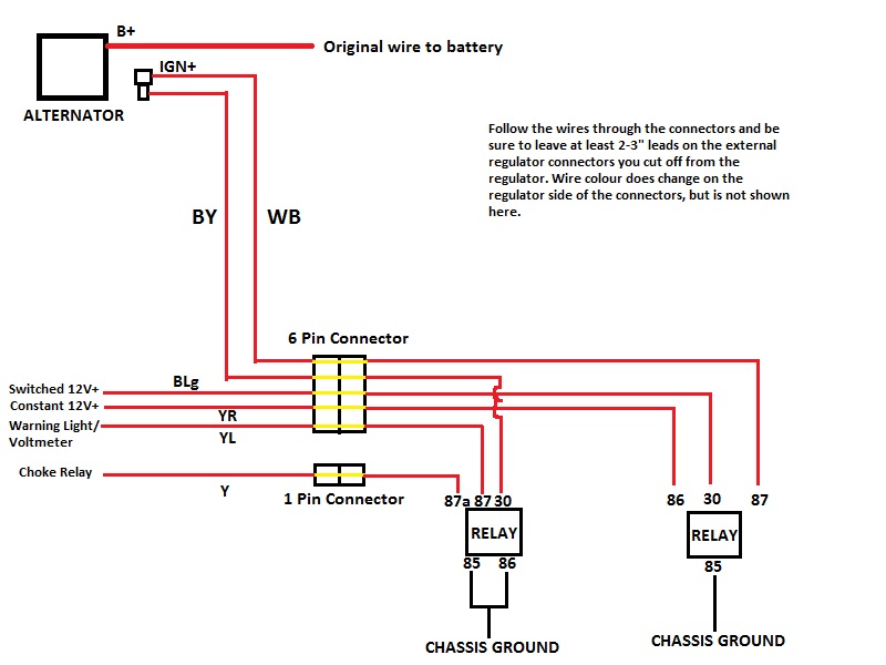
Alright, here is the requested wiring diagram. I tried to keep it simple so people only have to follow wires instead of trying to read pinouts. The pin numbers for the relays are the same for ALL 4 and 5 pin automotive relays and are shown right on the bottom of the relay beside each pin. Wire colour codes are the same as listed in a Haynes manual. I highly suggest you have a Haynes manual close by to refer to for locations of connectors and wire colour codes. Pictures of my setup will be posted tomorrow as it got dark outside before I could get them today.
I hope this is clear enough for all to understand. Remember, the ONLY extra wire you are adding is possibly extended leads from the external regulator connectors and wires from the relay grounds. The B+ terminal on the alternator is the same for all alternators. 2 pin connector at the alternator is wired as shown.
To elaborate on how this works a little more, the relays will react in the same way as the original external regulator did, in relation to the warning lights, choke relay, and switched power to the alternator. This is how the circuit passes power:
Engine not running and key on or engine running and alternator bad:
-Choke relay is 0V (not grounded, but no power) disabling magnet and heater
-Warning light/Voltmeter is grounded (Enabling both the light and tach override voltmeter)
-IGN+ on alternator is 12V
-2ND terminal on alternator is 12V
Engine running and alternator working fine:
-Choke relay is grounded enabling choke magnet and heater
-Warning light/voltmeter is 0V (again not grounded, but no power)
-IGN+ on alternator is 12V
-2ND terminal on alternator is 0V
That's true about the SAs having a tach/voltmeter. Sounds like using a relay is the better choice. At least on the old schools you can get away without as they only have a simple "G" dash light.
this is a good thread. if you guys want i can archive this.
If this does get archived, please change the title to read 79 only, not 79-80 as I incorrectly identified the 80 as also having an externally regulated alternator.
13x, I don't know what amperage the 79 alternator is capable of, but I'm 99% sure its not on par with the 80 and newer ones. Overall, unless you want to keep your 79 absolutely stock, there is no reason not to upgrade if the alternator or regulator are shot.
Jeff20B, I respect your knowledge of rotary engined cars as you have much more knowledge than I do. I don't want you to think I just ignored your post or anything like that. I looked into trying to do it without relays and with my knowledge of automotive electronics, your way just didn't make sense how it would work on a 79. Using the two relays as I did seemed to be the only way to make an internally regulated alternator work on a 79 without any issues. I wish the 79 was as simple as the early rotaries, but Mazda seemed to see a need for some more "creature comforts", if you can call it that. Overall, I kinda feel the wiring is a mess on the 79's from the factory, with all the extra stuff that was added.
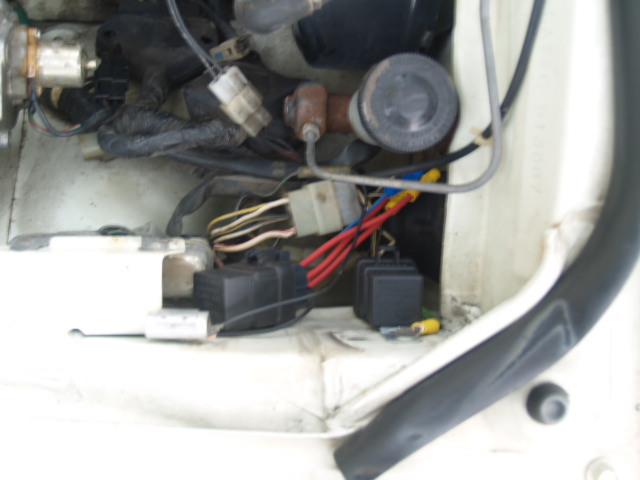
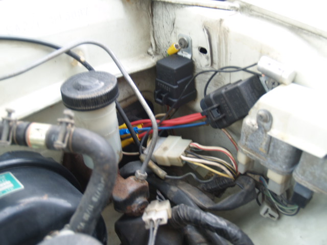
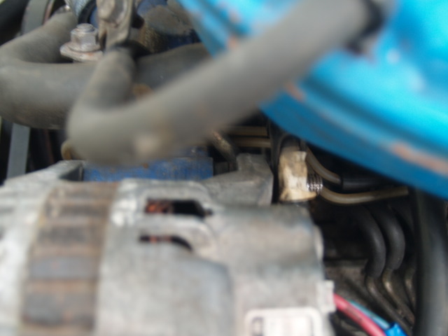
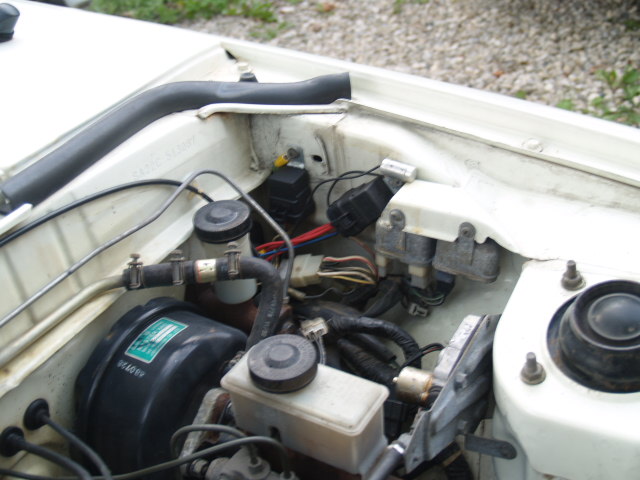
And here are the pictures. Before anyone notices it, I know I went against my advice above on the type of connectors to use. This preliminary install was to make sure everything worked fine and get the car running again, since it is supposed to go in for safety inspection tomorrow. I will make new connections with solder and heat shrink sometime through the winter. The alternator seen here is from an 88 13B.
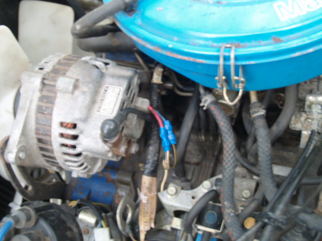
Picture showing the 3 washers used as a spacer in place of the stock 1" spacer due to the closer together ears of the 88 alternator.
Only comment; Though solder and heat-shrink is preferable for splices, a well-installed crimp connector of proper gauge will work just fine. After all, all the pins on the stock connectors are crimped in place.
The keys to a good crimp connection are using the right size connector for the wire gauge, and a good-quality crimping tool with actual machined dies intended specifically for insulated connectors, rather than the stamped-metal abortions that come in the 'kits' at the car parts stores.
This is true, and I didn't completely put down the insulated crimp connector. It is true that ALL the stock connectors are basically non insulated crimp connections, proving that a good crimp will hold for a long time. From what I have seen though, the average backyard mechanic that uses insulated crimp connectors doesn't install them right and they don't last much more than a year. Also, a good crimper is a must. As you said, the stamped metal ones are crap. I tried to use one once for an 18 gauge butt connector and it bent immediately. I've since got some real good solid steel crimpers. They are real nice quality and didn't cost much either, maybe $20.
I put a later Alt in my SA, All I did was disconnect the external reg, then connect the larger wire on the alt to the Fuse block like normal, the other two wires I left off. Works fine and has been this way 2 or 3 years.
Someone told me long ago that the Alt will self excite once reved up.
I put a later Alt in my SA, All I did was disconnect the external reg, then connect the larger wire on the alt to the Fuse block like normal, the other two wires I left off. Works fine and has been this way 2 or 3 years.
Someone told me long ago that the Alt will self excite once reved up.
Thats odd how it would work for you but not me. Not going to try to figure it out really as I wanted to keep my dash working like stock, and without wiring things the way I did its not possible for it to work like stock.
Also, not having the excite wire hooked up properly will diminish alternator performance. That wire no only initially excites the alternator coils but also provides the voltage comparator within the regulator a voltage to compare to in order to adjust to the proper voltage, at least to my understanding. Internal regulators are self adjusting, while external regulators are manually adjusted.
GM one wire will be the next upgrade. 150A and cheep to build.
I will check the voltage before and after start next time and with some revs to see where it is at.
should give an ideal of how good or not it is working.
Yes that will show everything properly. I would prefer people don't bog down this thread with information not really related to what I was trying to accomplish here.
What I have described in this writeup is how to do a alternator that works like stock for those of us that still use the original choke cable and tach setup. This is not the only way to install a later alternator, and other ways mentioned within the posts here may work depending on your setup. Also, the question of whether the alternator will self excite in a 2 or 3 wire alternator is a long debated subject. The alternator was designed with a separate excite wire connection, so it stands to reason that it should be used regardless of how well the alternator seems to charge without it.
Hi.
Were you said the lower vertical pin on the alt.. Goes to the Black/ yellow stripe wire from the five pin.
Does that ( black wire with stripe come out of the original 4 pin alt plug? Or do i run a new lead to the alt from the connection at the 6 pin plug?
Hi.
Were you said the lower vertical pin on the alt.. Goes to the Black/ yellow stripe wire from the five pin.
Does that ( black wire with stripe come out of the original 4 pin alt plug? Or do i run a new lead to the alt from the connection at the 6 pin plug?
This thread is 6 years old now, you're most likely not going to get the original guys to respond anymore. Take a few pics and we can help you out though
Hi.
Were you said the lower vertical pin on the alt.. Goes to the Black/ yellow stripe wire from the five pin.
Does that ( black wire with stripe come out of the original 4 pin alt plug? Or do i run a new lead to the alt from the connection at the 6 pin plug?
I followed this how to for my FC alternator upgrade. I didn't run any new wires to the alternator. It was all spliced into the existing harness for the external regulator on my SA.
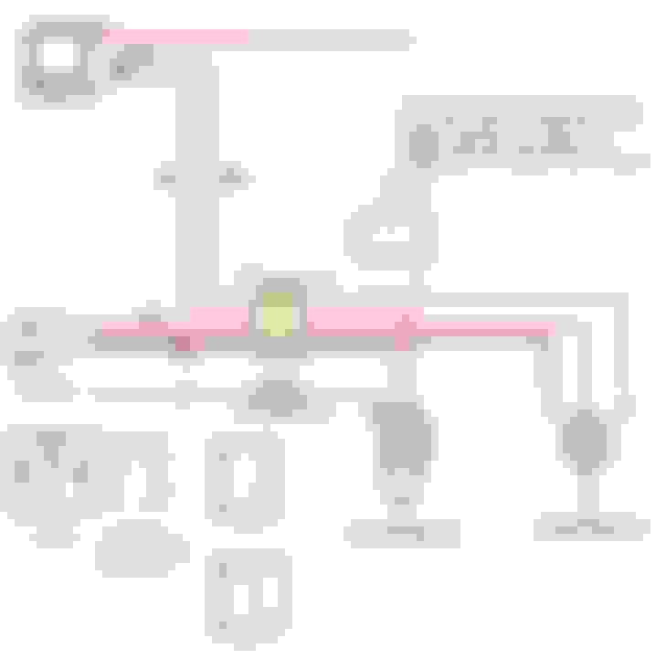
I followed the original diagram and noticed that the second relay was always on. Looking closer at the diagram, the constant 12v is connected to the relay coil. This also means that the switched 12v is always connected to the alternator horizontal connection. Also, the tach was not showing the voltage, and all the idiot lights where not on when you turned the key to the on position, but not running. This is because both coil connectors on the first relay were tied to ground, so that relay never changed.
The updated diagram removes the right relay, and just connects the BLg to the WB, and changes the positions of the three connectors that go to the right relay. Now the relay only gets thrown when the alternator shows power, on the BY wire. So, when there is no power from the alternator, the warning light (YL) is grounded, and the lights and "tach as voltage meter" work. Once the car is started, the relay is triggered, and the Choke circuit is set to ground instead.
Updated wiring diagram to remove external regulator
Hello I know this forum is old but I need to know where to get that relay. As I figured out a way to hook up the s5 (1989) alt into an 79 rx7 and with removing the regulator and adding fuses. An 12v 5 pin rely. In replacement of the regulator. This last wiring diagram is perfect except on the s5 alt u won't use the white/black wire I will use the Black/yellow wire. Newer wires for constant 12v is a must. This relay should help the alt show volts while egian off and while one the choke should be enabled, so that the tack works. Back as normal. I'll test it out. And let yall know. Before I do nxt week. If anyone refuses me to do this cus its bad and it would destroy something please let me know. I'll post pics when I finish and if it works.