When you click on links to various merchants on this site and make a purchase, this can result in this site earning a commission. Affiliate programs and affiliations include, but are not limited to, the eBay Partner Network.
I can confirm just your typical five-pin relay. I have an s4 alternator in my SA and it works the same as before I did the mod. This is the diagram I followed:
Ya the s4 alternator works just fine but I have an s5 alt so the wiring is different but the relay set up is the same. I'll post the newer diagram and post pics when done
Originally Posted by yeti
I can confirm just your typical five-pin relay. I have an s4 alternator in my SA and it works the same as before I did the mod. This is the diagram I followed:
So, I'm bringing this back from the dead. I recently bought an s6 alternator and I can't get it to excite. I have taken the alternator to be tested and it tests fine. Further reading suggests the L terminal is used to excite the alternator however for some reason that isn't happening for me.
I have B and S to battery and the L to the old L plug just like the above diagrams. I also have an s1 (SA) so I also have the above relay setup to bypass the external regulator. I can swap the alts and the old s4 alt work great but swap to the s6. No charge. What else should I try?
P.S. The dash light is good and all are incandescent lights. With the s4 alt after starting the car I often had to blip the throttle to at least 1100 RPM to excite the alternator.
P.P.S. Found this website. https://mazdarx7.ugocapeto.com/charging.shtml I believe I've done most of these tests. I'll redo them. I wonder if the issue resides in the relay wiring above?
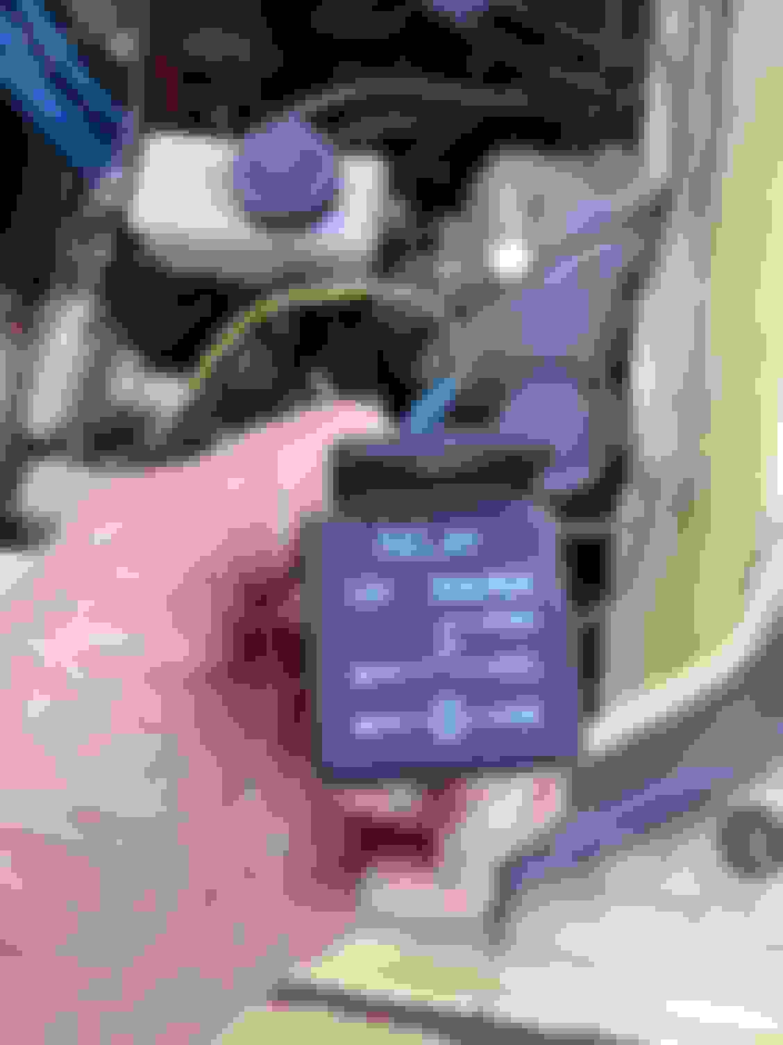
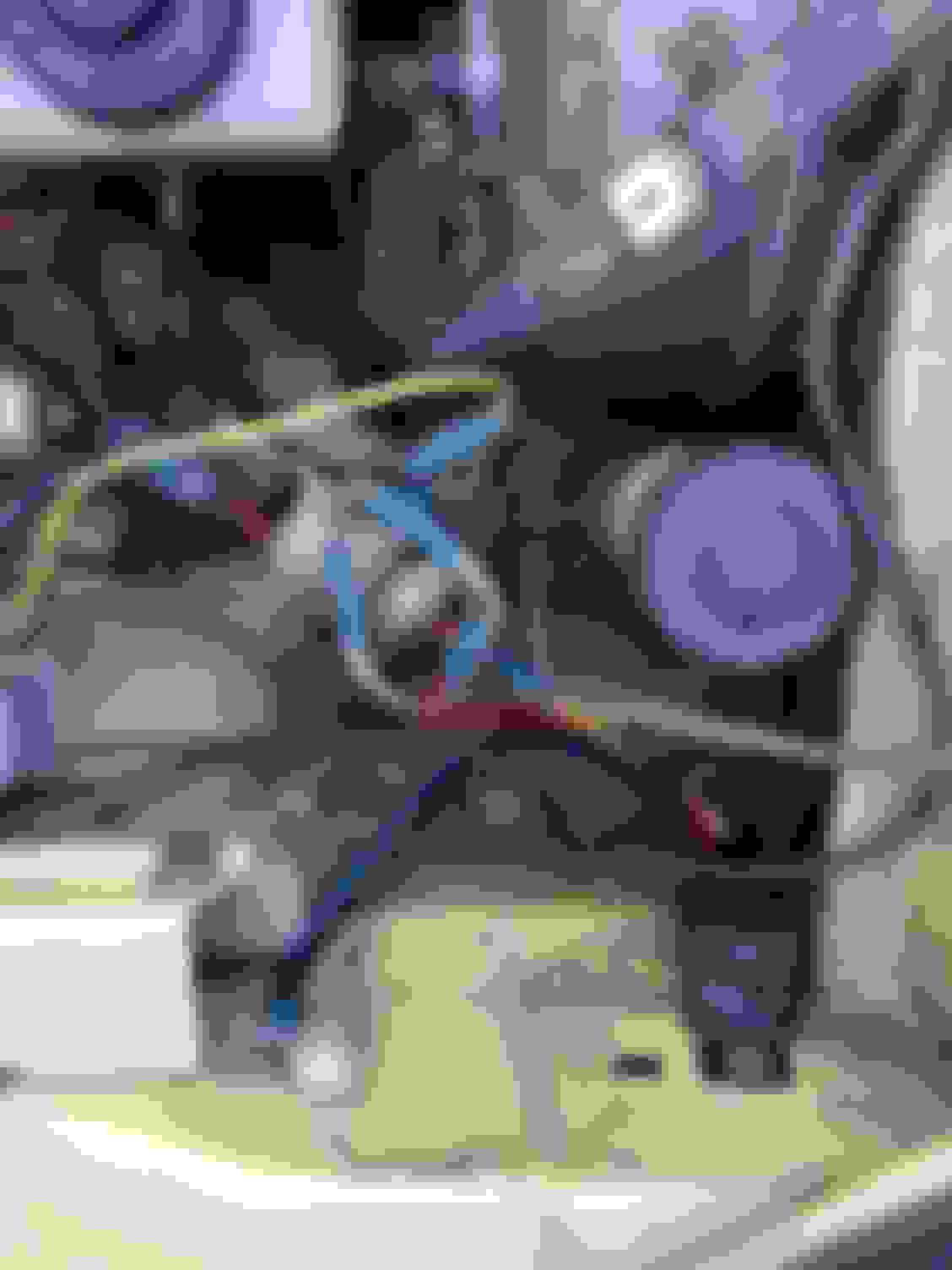
Just a heads up I came across this issue as well. I had to wire a relay in but differently. Same relay. I have the info at home and can send pics and lay out of how I got the s5 alternator hooked up. I even got the chock relay to work when car gets to temp. I'm working on an 1978/79 SA22c. I'm also doing a battery relocation and an fc fuse box instal. Give me 24 hrs I'll post a run down on how to get the newer alternator to run.
Originally Posted by yeti
So, I'm bringing this back from the dead. I recently bought an s6 alternator and I can't get it to excite. I have taken the alternator to be tested and it tests fine. Further reading suggests the L terminal is used to excite the alternator however for some reason that isn't happening for me.
I have B and S to battery and the L to the old L plug just like the above diagrams. I also have an s1 (SA) so I also have the above relay setup to bypass the external regulator. I can swap the alts and the old s4 alt work great but swap to the s6. No charge. What else should I try?
P.S. The dash light is good and all are incandescent lights. With the s4 alt after starting the car I often had to blip the throttle to at least 1100 RPM to excite the alternator.
P.P.S. Found this website. https://mazdarx7.ugocapeto.com/charging.shtml I believe I've done most of these tests. I'll redo them. I wonder if the issue resides in the relay wiring above?
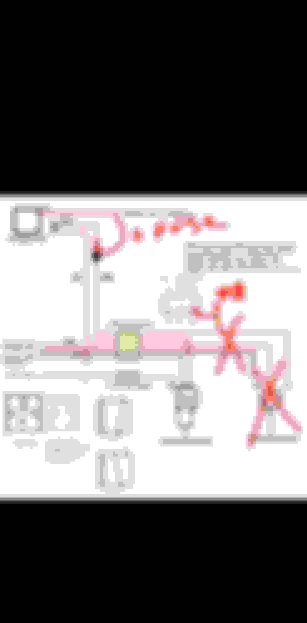
Okay, so I figured it out. I ended skipping the relay altogether, as I don't have a choke. But may add it back later if I need to detect when the engine is running (alternator is online).
Anyway, here is the updated diagram and a short explainer.
The diode is optional but probably recommended.
This will work with S4 (R L terminals) and s5/s6 ( S L terminals) alternators. The reason the old diagram would work is because apparently R L alternators can self-excite. This updated diagram allows for how it was intended (with one modification, the diode).
No Relay (no choke):
BLg to WB - BLg is switched 12v, WB is terminal R. This turns on the alternator's field circuit. (Could be eliminated if running s5/s6 S L alternators.)
BY to YL (dash light) and Y (choke). If you don't have a need for the choke circuit eliminate the relay. If you do wire the relay as above.
Relay (factory but without external regulator):
Engine not running: BY is connected to YL, allowing the dash light circuit to excite the alternator. Current is flowing dash to alternator.
Engine running (alternator excited): BY is switched to Y since current is now running from alternator to relay (and ground).
I haven't tested this updated diagram but I can't find anything wrong with it. Reason is I don't have a choke so didn't bother with the extra work. I assume it'll match Elhartd's findings. I did briefly test both with a diode and without. I already had paid for the diode so it won. However, without the diode, or relay for that matter, when the alternator is excited voltage is generated at the alternator side of the circuit. When voltage is applied to both sides of the light's terminals it cannot illuminate since there's no path for the current to flow. Before excitement the circuit is allowed to ground out at the alternator.
With the relay current flows flow the light to through the relay's 87a and out 30 then to BY. (Not sure why it doesn't trigger the relay other than the it would turn back off since the relay's only power source is currently 87a.) Anyway, once the alternator gets the excitement signal it needs the alternator to spin and create current. When that happens L terminal goes from 0v to 12+v. So then BY is now a power source and can trigger the relay. BY to both 86-85 (choke) and 86-87 (ground). Alternator stops spinning? 87a-30-86 circuit is back online.
Again the diode is unnecessary but it present in most wiring diagrams I found. It only helps protect the switched 12v circuit which may have the potential to keep your ignition online after shutdown (and in relayed setups, if the relay dies stuck in 87a.)
I'm tired but hopefully this final update is easy to follow. Thank you all.
Oh yeah no more throttle blipping to excite the RL alternators!
Ya I run with a choke. But when I did what u did, it did not have any power to the dash so I had to wire it diffently but basicly the same. I use a carb so the carb coke helps from inside the car. The only reason I use the choke cus once it gets to temp the choke releases to the open position.I've installed an s5 alternator into my 78-79 rx7 sa22c. here is how I did it. I went off this web page (https://www.rx7club.com/1st-gen-arch...st-gen-528440/)
ive got the gsl se rx7 12a motor with limited slip rear end. I even have 3/8 fuel lines to the carb. I got full time ignition on 12v coils. (stock is part time ignition on. 9v coils) Was made in 1978 shipping to the usa in 1979.
but I had to wire mine this way
Originally Posted by yeti
Okay, so I figured it out. I ended skipping the relay altogether, as I don't have a choke. But may add it back later if I need to detect when the engine is running (alternator is online).
Anyway, here is the updated diagram and a short explainer.
The diode is optional but probably recommended.
This will work with S4 (R L terminals) and s5/s6 ( S L terminals) alternators. The reason the old diagram would work is because apparently R L alternators can self-excite. This updated diagram allows for how it was intended (with one modification, the diode).
No Relay (no choke):
BLg to WB - BLg is switched 12v, WB is terminal R. This turns on the alternator's field circuit. (Could be eliminated if running s5/s6 S L alternators.)
BY to YL (dash light) and Y (choke). If you don't have a need for the choke circuit eliminate the relay. If you do wire the relay as above.
Relay (factory but without external regulator):
Engine not running: BY is connected to YL, allowing the dash light circuit to excite the alternator. Current is flowing dash to alternator.
Engine running (alternator excited): BY is switched to Y since current is now running from alternator to relay (and ground).
I haven't tested this updated diagram but I can't find anything wrong with it. Reason is I don't have a choke so didn't bother with the extra work. I assume it'll match Elhartd's findings. I did briefly test both with a diode and without. I already had paid for the diode so it won. However, without the diode, or relay for that matter, when the alternator is excited voltage is generated at the alternator side of the circuit. When voltage is applied to both sides of the light's terminals it cannot illuminate since there's no path for the current to flow. Before excitement the circuit is allowed to ground out at the alternator.
With the relay current flows flow the light to through the relay's 87a and out 30 then to BY. (Not sure why it doesn't trigger the relay other than the it would turn back off since the relay's only power source is currently 87a.) Anyway, once the alternator gets the excitement signal it needs the alternator to spin and create current. When that happens L terminal goes from 0v to 12+v. So then BY is now a power source and can trigger the relay. BY to both 86-85 (choke) and 86-87 (ground). Alternator stops spinning? 87a-30-86 circuit is back online.
Again the diode is unnecessary but it present in most wiring diagrams I found. It only helps protect the switched 12v circuit which may have the potential to keep your ignition online after shutdown (and in relayed setups, if the relay dies stuck in 87a.)
I'm tired but hopefully this final update is easy to follow. Thank you all.
Oh yeah no more throttle blipping to excite the RL alternators!
Last edited by elhartd; Aug 21, 2023 at 07:29 PM.
Reason: Better details
Hello I know this forum is old but I need to know where to get that relay. As I figured out a way to hook up the s5 (1989) alt into an 79 rx7 and with removing the regulator and adding fuses. An 12v 5 pin rely. In replacement of the regulator. This last wiring diagram is perfect except on the s5 alt u won't use the white/black wire I will use the Black/yellow wire. Newer wires for constant 12v is a must. This relay should help the alt show volts while egian off and while one the choke should be enabled, so that the tack works. Back as normal. I'll test it out. And let yall know. Before I do nxt week. If anyone refuses me to do this cus its bad and it would destroy something please let me know. I'll post pics when I finish and if it works.
@swig They posted later with additional feedback. I've also posted with my feedback. I'm going to suggest my write-up while they'll probably suggest theirs. Direct link to my post still in service today and after the car sitting all winter still fired up. If you want, and I probably should, I can provide documentation with photos. But since you replied to them and to be fair here is a direct link to their post, responding to mine.