
Are Hi-Performance HEI Modules a Waste?

Are Hi-Performance HEI Modules a Waste?
Hey guys,
I am going to be switching Gus (my '85 GS) over to a direct fire ignition system (TFIDFIS). In the process I'm going to be getting rid of the stock J109 ignition modules, and switching to GM HEI units. I like the GM HEI units since they are way cheaper and you can get them just about anywhere. I did this once before, and I used some of the regular Autozone 4-pin HEI modules on my 1983 GS and they worked great. Here's the question. I was looking around on Summit Racing for supplies and noticed that they have several "performance" HEI modules. They are more expensive than the standard HEI.
Would I see any improvement in performance, cold starts, hot starts, reliability, or idle smoothness using these instead of the standard HEI units from Autozone? Or are these performance HEI modules just a way for them to make a quick buck? Here are some links to the ones that I found....
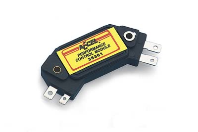
http://www.summitracing.com/parts/ACC-35361/?rtype=10
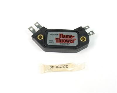
http://www.summitracing.com/parts/PNX-D2070/
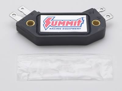
http://www.summitracing.com/parts/SUM-850100/
I am going to be switching Gus (my '85 GS) over to a direct fire ignition system (TFIDFIS). In the process I'm going to be getting rid of the stock J109 ignition modules, and switching to GM HEI units. I like the GM HEI units since they are way cheaper and you can get them just about anywhere. I did this once before, and I used some of the regular Autozone 4-pin HEI modules on my 1983 GS and they worked great. Here's the question. I was looking around on Summit Racing for supplies and noticed that they have several "performance" HEI modules. They are more expensive than the standard HEI.
Would I see any improvement in performance, cold starts, hot starts, reliability, or idle smoothness using these instead of the standard HEI units from Autozone? Or are these performance HEI modules just a way for them to make a quick buck? Here are some links to the ones that I found....
http://www.summitracing.com/parts/ACC-35361/?rtype=10
http://www.summitracing.com/parts/PNX-D2070/
http://www.summitracing.com/parts/SUM-850100/
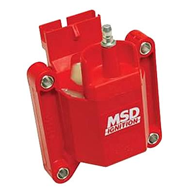
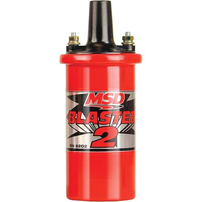
One other question regarding the coils I'll be using. I was originally planning on using MSD TFI style coils from Summit. Will these offer any advantages over a standard MSD Blaster 2 coil? It looks like the output voltage may be a little higher for the TFI coil. Also looks like it has lower internal resistance. Which coil would you guys recommend? I want to make sure the TFI is really worth my time before I start working on a custom mounting setup for it. The blaster coils obviously offer the advantage of being bolt-in. Yeah, I know you aren't supposed to mount them on their side, but let's just assume for the sake of the argument that they are bolt in because that's what I would do with them....
http://www.summitracing.com/parts/MSD-8227/
http://www.summitracing.com/parts/MSD-8202/
http://www.summitracing.com/parts/MSD-8227/
http://www.summitracing.com/parts/MSD-8202/
I believe they are oil cooled, and mounting them horizontally supposedly makes them hotter and prone to leaks. I have mounted them sideways before and never had any issues. Others may have had problems with leaks though. I'm not sure...
I know on gm HEI cars they are best when you have the supporting ignition mods along with it such as an msd/accel/mallory box, hipro dizzy, wires, and coil, not 100% but I'd venture to say the same applies to rotary engines as well.
What he is doing is an "Upgrade".
Do some reading about TFIDFIS using the search function.
Do some reading about TFIDFIS using the search function.
Trending Topics

I looked at the higher cost, higher performance HEIs but didn't feel they were worth
it in my case. I also had the thought that once I got it all working, then maybe in a
year I would try adding the HO HEI and TFI bits.
The Ford TFI coils spec out at, I think, around 35kv and the HO ones all
claim lower resistance and higher voltages (40-60kv). Right now with one TFI
per leading spark, it seems pretty strong.
The TFI coils are better than the older oil filled canisters. They have no mounting
issues, they handle heat better, they're a solid chunk of plastic instead of a
casing around the windings. They are a better all around coil when you look at the
resistance and charge they can put out.
Personally I would like to get a dyno run with my current setup and then switch
in the HO bits one at a time and see if theres any real difference. Theres that old
saying that once the mixture fires, any extra spark is just a waste. Who knows?
Awesome writeup by the way. I'm basically going to be reproducing your TFIDFIS setup. I'm planning on removing the trailing ignition too for simplicity. What are the dimensions of those TFI coils? I can't tell how big they are when looking at the pictures. Can you give me some measurements on them? I'm trying to decide where I'm going to mount two of them at.
Thanks,
Jamie
Thanks,
Jamie
I just went down and measured a spare I had. They are 3" x 3" around the square
iron rings and the widest dimension of the coil body is 3". The height including the
plugin and coil lead connection is almost 4". So I would say 3" x 3" x 4" for maximum
dimensions.
You could mount them on top of t he keg but I would not recommend
it because of the heat there. You saw how I did mine. Took maybe 1/2
an hour to make and mount those puppies.
I have used the round Jacobs coils before and if I remember correctly they also held higher voltage throughout the RPM than any other coil on the market. It's not always about the "peak" voltage. Those coils were the ones recommended by Killer Bee Rotary back in the day and were the ones that I used on my first 7.
Here is a link-
http://www.jacobselectronics.com.au/coils.htm
Here is a link-
http://www.jacobselectronics.com.au/coils.htm
Last edited by Rx-7Doctor; Aug 11, 2010 at 01:08 PM.
Jeff, while I've got you here....
I'm going to be removing the trailing ignition regardless of what ignition setup I end up going with. Is that going to cause me to lose my tachometer? This is on a 1985 GS.
I'm going to be removing the trailing ignition regardless of what ignition setup I end up going with. Is that going to cause me to lose my tachometer? This is on a 1985 GS.
That's deeper into the wiring specific to a 1st gen than I've delved, so at first I'll say yes. However you should be able to keep your tach if you simply stop using your leading wire and switch over to the trailing wire for your leading ignition. In other words, repurpose the stock little yellow trailing wire over to the leading ignitor. Likewise the stock trailing coil now becomes the new leading coil. This lets you keep the tach because it is now reading a leading signal even though it is still wired into the trailing wires, somewhere under all the black wire wrap. Like I said I've never dug that deep into a 1st gen's ignition wiring so this is what I'd do in the beginning.
They make the old schools (with points) easier with a seperate wire specifically for the tach. The 1st gens have the tach signal wire connected into the trailing wire somewhere between the tach and the coil in a location unknown to me.
So take the advice above as a way to get yourself started on the path to keeping your tach functioning on leading and take it to the next level. Who knows, you may find the juntion point down in the wiring somewhere, on not even worry about it. Good luck to you.
Joined: Jun 2008
Posts: 8,376
Likes: 28
From: Chino Hills, CA
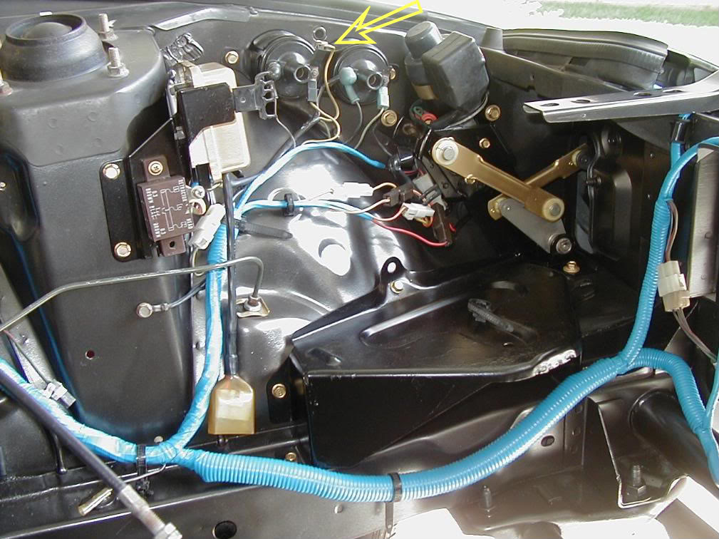
Contrary to FB's, it also connects off the leading coil (since SA emcon shuts down the trailing ig under some circumstances to help keep the thermal reactor fed.) Connects off of a spade lug that's bolted to the coil terminal... see the arrow:
Full Member
Joined: Sep 2005
Posts: 186
Likes: 0
From: Pueblo, Colorado
On a similar note; does anybody have 'scope measurements for the electronic distributors? I have one laying around to replace my points ignition, but I want to double check/tweak to spec. before it goes into the car.
Just a minor correction for future reference: all SA's also have the separate tach wire connecting at the coil terminal, regardless of points (78-79) or electronic ignition (80).
Contrary to FB's, it also connects off the leading coil (since SA emcon shuts down the trailing ig under some circumstances to help keep the thermal reactor fed.) Connects off of a spade lug that's bolted to the coil terminal... see the arrow:


Contrary to FB's, it also connects off the leading coil (since SA emcon shuts down the trailing ig under some circumstances to help keep the thermal reactor fed.) Connects off of a spade lug that's bolted to the coil terminal... see the arrow:


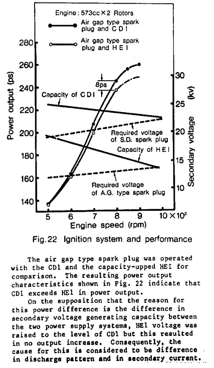
^ Can someone explain this chart to me. I'm an electrical moron. I don't even know the real differences between HEI and CDI. All I know is that I bought some crap from Autzone last time, wired it up and it worked. School me.... 
Looks like to me up to 5K rpms its a tie and after that CDI edges out the HEI
by a small amount up to 8k rpms. CDI == expensive, HEI == affordable.
I'd like to know the source for that diagram and further context so we can
fully understand whats happening. I know I've always heard that rotaries
do better with an inductive ignition compared to a CDI one but this chart
seems to cleam otherwise.
Whats an air gap plug look like anyway?
Joined: Jun 2008
Posts: 8,376
Likes: 28
From: Chino Hills, CA
HEI is inductive-based, generating it's energy pulses by building up and then rapidly collapsing a magnetic field within a coil (also known as an inductor). The collapsing magnetic field generates the high secondary voltage that fires the plug. It's a direct descendant of the classic points/coil ignition.
CDI is capacitive-based, generating it's energy pulses by charging and then rapidly discharging large capacitors (also known as condensers). The charge voltage may or may not be stepped up by a transformer depending on the age of the design, but the energy storage mechanism is capacitive.
Basically, both systems are trying to do the same thing; generate a high-powered, high-voltage, relatively short-duration output from a 12V input. Two roads to the same destination.
The design of the CDI system is more complicated, and the components cost more. The HEI system is simpler and cheaper.
The graph is indicating that the CDI produces a more powerful (higher wattage) spark than does HEI, and maintains that power advantage better as RPM increases.
As RPM goes higher, there's less time for the ignition system to build up charge before discharge, and less time to discharge. Capacitive systems can generally charge & discharge faster than inductive systems within the same power levels, though at a higher cost of components.
The power units used on the chart (PS, derived from the German Pferdest�rke = horse strength; like 'horsepower') is kind of obsolete erminology with regard to electrical systems; people use watts or kilowatts now for electrical. One PS equates to about 735 watts.
In electrical system, power (watts) is equal to potential (volts, e) multiplied by current (amps, i). P=ie.
Voltage is important because it better enables the arc jumping between the plug electrodes (and across the gap in the distributor), and a higher voltage system will arc better through fouling & at higher chamber pressures ( higher pressure gasses have more resistance to electrical flow) but watts delivered determine the total heat energy of the arc and thus it's ability to ignite efficiently.

Oh, and "Air gap" (AG) spark plugs are the kind we're used to seeing; a center electrode with one or more ground electrodes around it, separated by an air gap.
The other type of plug the chart points to (the SD plug mentioned in the upper 'wedge' chart) is a "Surface Discharge" plug, which you don't see much. Electrodes are embedded in a flat ceramic face, so the arc forms across the ceramic surface. They were initially designed to eliminate electrode burn-off and also prevent electrode fracture and fouling, but they take more energy to fire.
CDI is capacitive-based, generating it's energy pulses by charging and then rapidly discharging large capacitors (also known as condensers). The charge voltage may or may not be stepped up by a transformer depending on the age of the design, but the energy storage mechanism is capacitive.
Basically, both systems are trying to do the same thing; generate a high-powered, high-voltage, relatively short-duration output from a 12V input. Two roads to the same destination.
The design of the CDI system is more complicated, and the components cost more. The HEI system is simpler and cheaper.
The graph is indicating that the CDI produces a more powerful (higher wattage) spark than does HEI, and maintains that power advantage better as RPM increases.
As RPM goes higher, there's less time for the ignition system to build up charge before discharge, and less time to discharge. Capacitive systems can generally charge & discharge faster than inductive systems within the same power levels, though at a higher cost of components.
The power units used on the chart (PS, derived from the German Pferdest�rke = horse strength; like 'horsepower') is kind of obsolete erminology with regard to electrical systems; people use watts or kilowatts now for electrical. One PS equates to about 735 watts.
In electrical system, power (watts) is equal to potential (volts, e) multiplied by current (amps, i). P=ie.
Voltage is important because it better enables the arc jumping between the plug electrodes (and across the gap in the distributor), and a higher voltage system will arc better through fouling & at higher chamber pressures ( higher pressure gasses have more resistance to electrical flow) but watts delivered determine the total heat energy of the arc and thus it's ability to ignite efficiently.
Oh, and "Air gap" (AG) spark plugs are the kind we're used to seeing; a center electrode with one or more ground electrodes around it, separated by an air gap.
The other type of plug the chart points to (the SD plug mentioned in the upper 'wedge' chart) is a "Surface Discharge" plug, which you don't see much. Electrodes are embedded in a flat ceramic face, so the arc forms across the ceramic surface. They were initially designed to eliminate electrode burn-off and also prevent electrode fracture and fouling, but they take more energy to fire.