
Header Build Thread

Thread Starter
Senior Member
Joined: Mar 2006
Posts: 634
Likes: 0
From: Canada
Header Build Thread

I just happened to not like any of the headers out there, well more the price of them so i built one my self. Heres the "How To" on this header.
I started with taking some measurements of the stock exhaust. You will need to know how long your header is going to be, how low it has to go, and runner angles. I measured the stock exhaust manifold to get a rough idea.
First of all i started by buying
- Thick Gauge U bend, 2 1/4" ID x 24"
- Steel Plate, 6" x app 10" x 3/8.
- New exhaust manifold gasket.
- 1' of 2 1/4" tubing, thick stuff remember.
You will need:
- All of the above
- Black Felt or Marking Tools
- Plasma or Cutting Torch
- Mig Welder
- Drill or Drill Press
- 1/4" Drill Bit
- 1/2" Drill Bit
- Grinder
- Round and Basterd File
- Die grinder
The first step is to take the flat bar and your exhaust manifold gasket and trace it onto the steel. Marking the centers of the ports and drill holes is a good idea at the point, yet you will have to do it later after you have cut it out. I also made a copy on paper for dimensionial purposed. Make sure to note that gasket holes that mate to the exhaust ports are larger than your U-Bend to allow the bend to fit inside the pipe. DONT OVER CUT, leave just enough room to file.
After cutting out the shape, clean all the edges with your grinder, making sure to leave the ends flat on the top and bottom to allow for clamping while drilling. Lay your gasket overtop of the shape and match accordingly. Mark the holes with your felt and punch the middle with a center punch. Drill each hole with the 1/4" bit then the 1/2" bit. If you havent already, cut out the ehxuast ports out following your guides. Again, DO NOT OVERCUT.
Note: To fit the tubing into the plate the hole will not be exactly round due to the shape of the U-Bend from stretching while it was manufactured.
At this point you should have the plate clean & ready to bolt on. Now you have to measurements from your manifold and use them to cut your U bend, semi roughly. Obviously only in the bended section at this point. Make sure that they do not stick too far out from your plate to where they can hit the firewall or fender wall. Slide the tubing inside your holes and make sure they are parallel to the inside of the hole.My header runners actually run ontop of eachother because its the easiest way of doing it, rather than becide eachother. You can measure the tube lengths with them resting in place at the correct angle, mark with a black felt. Cut the tubing to the disired length cutting an extra 5 1/2 off, you might only need to cut 2" if your U bend is short, this is to make room for your collector.
After doing this you can mig weld the inside of the tubing at the correct angle with a 1/4 gap, or if you want to make a littler further it can go all the way to about 3/4 of an inch BETWEEN THE RUNNERS, just remember to account for angles. While welding make sure that the tubing is half way through the plate so that you can port the inside to make it smooth, this also stops the tubing from un-trueing the plate surface due to excess weldment.
Now you can clean the insde of the tubing using a file, die grinder, flapper wheel or cutting tools, what ever you feel nesessary to make it smooth. Mines like glass.
After that weld for strength on the outside of the tubing, making sure not to put too much heat into the tubing.
When that is done you can start making your collector, aslong as your header is to length already you can grab your 12" piece of 2 1/4" tubing and lay it out. Easiest way to position it is on the header, mark where you want the tubing to go. You can choose a long angle for the collector or you can choose a short one, a longer one wont create so much back pressure and heat. Cut your angles so that your tubing will point at eachother and meet in the middle, using a straight edge and your marker you can achieve straightness very easily. Sand or file untill true and a good fit is found.
NOTE: How much you cut off while making the large cuts on the tubing will determine the diameter of the turbing of the exit pipe.
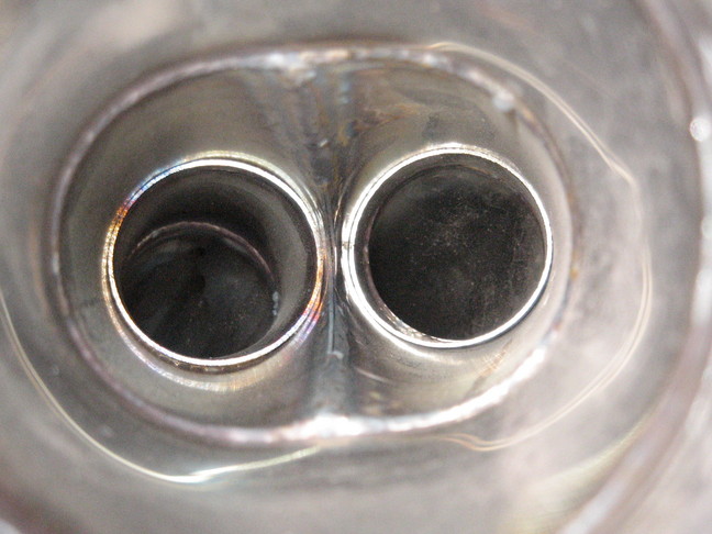
Now you can mark and weld your tubing together to make the collector itself. Welding the inside was a good idea, but i had to do it with a oxy-aclyn welder. Make sure that the two inlets match the header, wider is ok because you can always chop a little off. The ends will need to be sanded to match the header. Weld the header to the collector in a fashion where you can control warping, tack welds are your friends.
Check for leaks with steam, or water, then buff the inside with your flapper one more time all the way through and you will be good to go. Weld on your last exhaust flange and you can bolt it right up.
Btw, this was my trial run, my next one will be a turbo header and in stainless not exhaust tubing.


Last edited by chedda_j; Dec 8, 2006 at 05:40 PM.


Looks great to me!!!!
I wish I had the ***** to make my own header..I just left it to RB. Only reason I didnt attempt such a thing is the scavaging effect. While there is much theory out there, no one seems to be able to come up with any solid formulas, or any set lengths for optimal pulse tuning.
Gotta say good job on it tho, the collector looks better than anything Ive seen from even racingbeat I must say. Now we just need to hear how it works for ya!
Trending Topics
Joined: Apr 2006
Posts: 3,740
Likes: 6
From: Las Vegas, NV
Looks good. Only thing though. I read that headers work right when the tubes are the same lenght, so one of the exhaust gases in one tube doesn't leave before the other. I f this happens backpressure will make it not flow at its full potential. Thats what I read from somewhere. I forgot though. Good work though
Nice fabrication work there. I'm currious to see how they work. Remember there is alot of work and theory involved in making a "Functional" header.
Recommend you do not run header wrap though.
Recommend you do not run header wrap though.
Airflow is my life
Joined: Aug 2002
Posts: 6,736
Likes: 2
From: Orlando, Fl
Nice work on the construction.  I like the collector especially, of course I cant see the inside to judge how well the merge is though. Two points of constructive criticism, both of which can be changed if your so inclined. One is what twinkletoes mentioned. The tubes should be of equal length as measured down the centerline, and the exit from the flange should come straight out for as long as you can make it still fit and then have a nice gentle radius on the turn (which I like on yours) . Thats my biggest bitch about the RB header. It's made to clear on every car (read: RHD)which meant compromising on ultimate performance. Theres a ton of room to do this on a LHD 1st gen. But nice work man.
I like the collector especially, of course I cant see the inside to judge how well the merge is though. Two points of constructive criticism, both of which can be changed if your so inclined. One is what twinkletoes mentioned. The tubes should be of equal length as measured down the centerline, and the exit from the flange should come straight out for as long as you can make it still fit and then have a nice gentle radius on the turn (which I like on yours) . Thats my biggest bitch about the RB header. It's made to clear on every car (read: RHD)which meant compromising on ultimate performance. Theres a ton of room to do this on a LHD 1st gen. But nice work man.
Thread Starter
Senior Member
Joined: Mar 2006
Posts: 634
Likes: 0
From: Canada
Thanks for all the support, if i dont go with the turbo application just yet i am planning on tig welding a stainless one.
Yes the whole theory about the lengths being the same so that the pulses will actually pull the exhaust from the opposite cylinder was looked at while building this header, yet this was the trial run and only the first of a few headers im planning on making. From what i understand, the longer the distance before the runners meet at the collector the better hi-end power is created, and the opposite for short runners.
I am worried alittle bit about scouring, thats why im planning on making a stainless one. If i do go to a turbo app or possibly a small block then i will be willing to sell it at stock, il keep everoyne up to date on when im building the stainless one. It shouldnt be any longer than two months.
Originally Posted by Rx7carl
Nice work on the construction. I like the collector especially, of course I cant see the inside to judge how well the merge is though. Two points of constructive criticism, both of which can be changed if your so inclined. One is what twinkletoes mentioned. The tubes should be of equal length as measured down the centerline, and the exit from the flange should come straight out for as long as you can make it still fit and then have a nice gentle radius on the turn (which I like on yours) . Thats my biggest bitch about the RB header. It's made to clear on every car (read: RHD)which meant compromising on ultimate performance. Theres a ton of room to do this on a LHD 1st gen. But nice work man.
I like the collector especially, of course I cant see the inside to judge how well the merge is though. Two points of constructive criticism, both of which can be changed if your so inclined. One is what twinkletoes mentioned. The tubes should be of equal length as measured down the centerline, and the exit from the flange should come straight out for as long as you can make it still fit and then have a nice gentle radius on the turn (which I like on yours) . Thats my biggest bitch about the RB header. It's made to clear on every car (read: RHD)which meant compromising on ultimate performance. Theres a ton of room to do this on a LHD 1st gen. But nice work man. I remember a while back seeing a header that a local guy had designed, and it was done really well. He had taken some mandrel bent tubes and cut 4 equal length and curved pieces, and fiddled with them until he had 2 coming off each rotor meeting at the same place. This way he was sure that the bends hadnt differed between the rotors, and since the front rotors exhaust has more distance to travel, he knew the internal distances were the same because the pieces were identical for each rotor. Then after, he just extended each exhaust tube back from the curved parts the same amount and collected them some 3 ft. back. It looked like a really good idea, mainly because each rotors exhaust saw the same curves, and distance (another downside to the RB unit.)
This thread is really making me want to go out and build the ultimate header...If only I had more time....
Originally Posted by chedda_j
Thanks for all the support, if i dont go with the turbo application just yet i am planning on tig welding a stainless one.
Yes the whole theory about the lengths being the same so that the pulses will actually pull the exhaust from the opposite cylinder was looked at while building this header, yet this was the trial run and only the first of a few headers im planning on making. From what i understand, the longer the distance before the runners meet at the collector the better hi-end power is created, and the opposite for short runners.
I am worried alittle bit about scouring, thats why im planning on making a stainless one. If i do go to a turbo app or possibly a small block then i will be willing to sell it at stock, il keep everoyne up to date on when im building the stainless one. It shouldnt be any longer than two months.
Yes the whole theory about the lengths being the same so that the pulses will actually pull the exhaust from the opposite cylinder was looked at while building this header, yet this was the trial run and only the first of a few headers im planning on making. From what i understand, the longer the distance before the runners meet at the collector the better hi-end power is created, and the opposite for short runners.
I am worried alittle bit about scouring, thats why im planning on making a stainless one. If i do go to a turbo app or possibly a small block then i will be willing to sell it at stock, il keep everoyne up to date on when im building the stainless one. It shouldnt be any longer than two months.

let this be a little example  (read ... lots of money) its sdj incase anyone is woundering.

This is jus the o2 bung for wideband and what not.
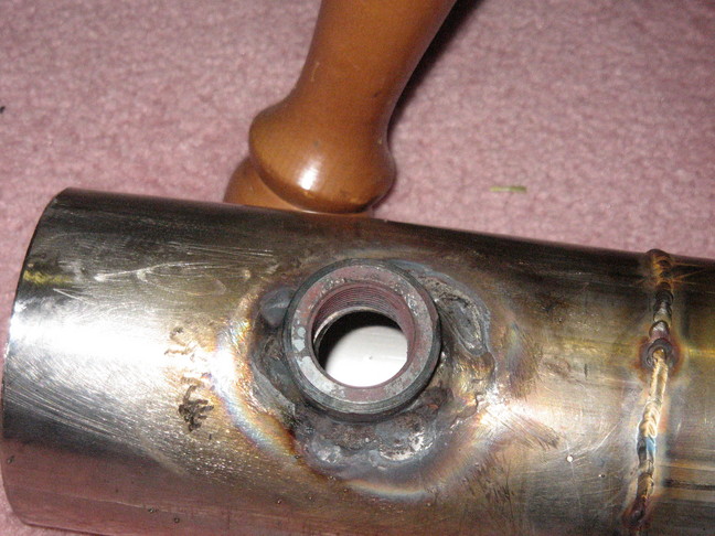
All stainless merges into 2.5"
(read ... lots of money) its sdj incase anyone is woundering. This is jus the o2 bung for wideband and what not.
All stainless merges into 2.5"
Thread Starter
Senior Member
Joined: Mar 2006
Posts: 634
Likes: 0
From: Canada
If the runners are larger than the 2" than they wouldnt have to be aslong to create the proper velocity right? Its all about how much cubic feet of air is exiting before it is compressed?
Nice stainless one but i would have went for a little bit different design, nice tho.
Nice stainless one but i would have went for a little bit different design, nice tho.
The SDJ header is THE header to have. Out performs all others and dyno proven. Too large of exhaust tubes coming off of the block will actually slow down exhaust velocity, which is not a good thing. One reason for SDJs better performance is the longer straight run from the block before the turn. Turning too soon will create more backpressure, which causes more overlap and dilutes the intake charge more.
Something to consider if you wish to pursue more designs.
Something to consider if you wish to pursue more designs.
Wankel Me This!!
Joined: Nov 2005
Posts: 1,241
Likes: 0
From: St Cath Canada
Nice job dj55b. I barrowed my buddys RB header (I think that is the name) so I can copy it. I am starting next week because I need the metel. But when I get done I will post new pics.

Heres a bad mama-jamma too... 
Although I wonder how much of a difference it will really make. These headers are more like pieces of art. When compared to the $130 pacesetter, does the extra 3-400 dollars spent actually net that much more of a gain? You can't tell me any of those headers are going to make more than a 10 hp differnce over a cheap header. SO why not save up the extra cash? Buy a blower or something that will net you more than a 10% hp gain.
IMHO it would be better to buy a cheaper header and save your money for more efficient mods.
Then again if you have the money why not spend it... I'm poor so it's hard to think that way.
And on another note, why use a collector at all? Why not run the two pipes individually the length of the car, each with it's own separate muffler?
Obviously this doesn't work well or the "race" guys would be doing it. I was just wondering why it is better to have them directed to a collector.