GSL vs GSL-SE fuel hardlines

 02-01-19, 03:40 PM
#27

ID1050X injectors, so I was just going to start at 43psi unless someone tells me differently.
One more question. Tube nut and sleeves with flared hard lines... or those crush washer style adapters? I'm thinking that flaring the line will be better long term with less chance of leaking. If I'm gonna go through the trouble of making my own lines, might as well do it right.
So fuel system start to finish will be... (bare with me, this is more for my own notes than for public consumption...but I digress)
Holley retro fit kit with hydramat and 255lph pump
Feed Line -
A short soft line off the tank to a hard line, to the area where the original pump was located. There I will add the check valve and fuel filter. I'm probably going to ditch the original fuel pump mounting pan as it will make running the lines easier and access to the fuel filter will be easier. I think its only purpose was to dampen the vibrations from the pump anyway, it would be nice to have it as a protective plate, but the parking brake line is right there and the way the factory lines were routed is kind of convoluted. It will be easier to to just straight shot through that area with the pump and check valve tucked up and mounted with the original stud for the protective plate and further supported by well bent hard lines.
More of the same, I basically need to exactly recreate the bends in the original line with 3/8.
Keep all the stock hard lines. Only change from factory is using a solenoid instead of a port air vacuum source.
One more question. Tube nut and sleeves with flared hard lines... or those crush washer style adapters? I'm thinking that flaring the line will be better long term with less chance of leaking. If I'm gonna go through the trouble of making my own lines, might as well do it right.
So fuel system start to finish will be... (bare with me, this is more for my own notes than for public consumption...but I digress)
Holley retro fit kit with hydramat and 255lph pump
Feed Line -
A short soft line off the tank to a hard line, to the area where the original pump was located. There I will add the check valve and fuel filter. I'm probably going to ditch the original fuel pump mounting pan as it will make running the lines easier and access to the fuel filter will be easier. I think its only purpose was to dampen the vibrations from the pump anyway, it would be nice to have it as a protective plate, but the parking brake line is right there and the way the factory lines were routed is kind of convoluted. It will be easier to to just straight shot through that area with the pump and check valve tucked up and mounted with the original stud for the protective plate and further supported by well bent hard lines.
1/4 NPT to -6AN adapter
-6AN straight hose end
~2ft of hose
-6AN straight hose end
-6An male/male adapter
-6AN tube nut and sleeve
~2ft of 3/8 hard line to original pump location
---
-6AN tube nut and sleeve
Vibrant Performance check valve (already have it)
-6AN female/female 90 fitting (already have it)
Fuelab 81801-1 10 micron filter (already have it)
-6AN tube nut and sleeve
~10ft of 3/8 hard line to engine bay
---
-6AN tube nut and sleeve
-6AN male/male adapter
-6AN 90 degree hose end
~1ft of hose
-6AN 45 degree hose end
(fuel rail has -6AN male fittings)
Return Line-6AN straight hose end
~2ft of hose
-6AN straight hose end
-6An male/male adapter
-6AN tube nut and sleeve
~2ft of 3/8 hard line to original pump location
---
-6AN tube nut and sleeve
Vibrant Performance check valve (already have it)
-6AN female/female 90 fitting (already have it)
Fuelab 81801-1 10 micron filter (already have it)
-6AN tube nut and sleeve
~10ft of 3/8 hard line to engine bay
---
-6AN tube nut and sleeve
-6AN male/male adapter
-6AN 90 degree hose end
~1ft of hose
-6AN 45 degree hose end
(fuel rail has -6AN male fittings)
More of the same, I basically need to exactly recreate the bends in the original line with 3/8.
-6AN 180 degree hose end
~1ft of hose
-6AN straight hose end
Fuellab 52501 fuel pressure regulator
-6AN tube nut and sleeve
~12ft of 3/8 hard line
-6AN tube nut and sleeve
-6AN male/male adapter
-6AN straight hose end
~2ft of hose
-6AN straight hose end
-6AN to 1/4 NPT adapter
EVAP system~1ft of hose
-6AN straight hose end
Fuellab 52501 fuel pressure regulator
-6AN tube nut and sleeve
~12ft of 3/8 hard line
-6AN tube nut and sleeve
-6AN male/male adapter
-6AN straight hose end
~2ft of hose
-6AN straight hose end
-6AN to 1/4 NPT adapter
Keep all the stock hard lines. Only change from factory is using a solenoid instead of a port air vacuum source.
1/4 to 1/8 hose barb
~2ft of vacuum hose to hardline
Replace all the check valve hoses with new stuff
original hard line to engine bay.
hose to charcoal canister.
larger hose to hardline and to filler neck
hose to purge valve
hose to vacuum manifold
purge valve will be controled with solenoid and separate hose to vacuum manifold
Vacuum Lines, OMP, Etc
I have the side draft cast manifold I picked up used. Two holes were already drilled near the primary ports and they had brake bleeder screws in there. I'm guessing they were for OMP lines but I found two issues with this approach. One, there wasn't much to grip a hose on a bleeder and two, oil only drops into the primary ports when it should be distributed to both primary and secondary. I was also worried about the lines being subjected to vacuum, but if the inlet ports are small enough, it shouldn't be an issue. Anyway, I'm tapping new holes higher up on the manifold and I ordered some new fittings that should work better than a bleeder screw.
As for the two holes near the primary ports, those have been tapped for 1/4" NPT barbs and will run to a vacuum manifold. Off that manifold will be two lines for the purge system (one to pull air in from case, one to connect to solenoid which opens the valve). I have two more ports on the manifold, but 3 more devices. I'm thinking of just adding a T to one line and sending one side to the FPR and the other to the ECU. The last port will go to the cruise control module.
Speaking of cruise control, I traced the wiring diagram and when I pull the emissions computer and replace it with my Adaptronic ECU, it should still work since it uses a separate computer that only reads information from speedometer and brake pedal. I have a linkage system that I can adapt for two cables, one from gas pedal, and the other from the cruise control unit which will pull on the gas pedal similar to how the carb handles it.
Wiring is still bouncing around in my head. I need a few relays for things like the pump, e-fan, and direct fire coils. I'm going to redo the grounding on the engine bay, but the rest of the engine bay harness not related to the EFI conversion will remain intact so I don't have to touch anything like lights, and factory gauges. I need to draw everything out before I start so I'm not forgetting anything.
02-02-19, 08:46 AM
#28

Very informative thread for guys switching to EFI!
I had a similar issue when I went with an upgraded fuel pump and regulator for a carb'd application. My 1982 GS return line (0.25") was too restrictive and I could not get fuel pressure low enough and the pump wasn't happy.
All I had to do was add a return line, and I went with 3/8 aluminum hardline and used AN tube nuts as you have described above. I found it worked very well and I was able to use the original hardline as a template and get a very well fitting hardline bent up on the first try. Then I cut it to final length and did the flares (it is very easy to forget to add tube nut and sleeve before flaring...!).
Also it looks very clean when you go from the flared hardline with AN Bnut to the barbed hose adapter.
Hardline to chassis, you should be able to use the OEM routing and clamping, especially where the lines run with the brake lines beside the frame rail. Rubber cushioned P-clamps can be used where it needs extra support.
I have been a huge fan of Summit racing to get all of the necessary supplies for work like this, they have every single fitting you could need. I found their fuel line to be nice to work with, and 25feet is just enough to give you extra if you mess up the line. https://www.summitracing.com/parts/sum-g2538
Also for wiring, you probably have already done this but I found it handy to de-pin and remove the OEM wiring that is not necessary. You can strip away anything that is not needed and still leave the rest of the harness intact.
02-02-19, 11:53 AM
#29
Great info Tommy. I'm surprised my REPU doesn't have that issue you mentioned with fuel pressure being to high. I have it at 35psi at idle and it bumps up a little more under throttle, or at least that's how it was when I did my road tune. Haven't stopped by the shop to check things out since they said it was done. I'm curious as to how much they changed on the tune. I was using an Oreilly branded fuel pump for a early 90's Ford F150. I had planned to use a walbro but the one I got arrived DOA and that day I just wanted to see it run. I got the replacement walbro in the mail later...which is the one I displayed in the photos above. I guess I'll save it for when the Oreilly one fails.
For wiring, there isn't much I won't be using from the factory setup. Basically just the power wires to the coils and the distributor are getting deleted. I broke open the loom on all that and just decided to terminate what I wasn't going to use because the alternative was cutting open the loom all the way to the ignition. I'm starting from scratch with the engine harness (the two connectors on the passenger side of the engine bay). All of the leads on that which were originally used for solenoids and emissions stuff are going to be re-purposed for the fuel injection sensors and what not. I started a spreadsheet to make sure I have enough leads going between those connectors and the passenger side floor where the emissions computer is. I'm hoping to just remove the emissions computer and swap in the adaptronic with a short plug-and-play harness.
For wiring, there isn't much I won't be using from the factory setup. Basically just the power wires to the coils and the distributor are getting deleted. I broke open the loom on all that and just decided to terminate what I wasn't going to use because the alternative was cutting open the loom all the way to the ignition. I'm starting from scratch with the engine harness (the two connectors on the passenger side of the engine bay). All of the leads on that which were originally used for solenoids and emissions stuff are going to be re-purposed for the fuel injection sensors and what not. I started a spreadsheet to make sure I have enough leads going between those connectors and the passenger side floor where the emissions computer is. I'm hoping to just remove the emissions computer and swap in the adaptronic with a short plug-and-play harness.
02-02-19, 02:14 PM
#30
Moderator
iTrader: (3)
Join Date: Mar 2001
Location: https://www2.mazda.com/en/100th/
Posts: 30,849
Received 2,613 Likes
on
1,852 Posts
you might check with Mr Yaw, but it should improve atomization, and in theory this helps efficiency (BSFC)
02-02-19, 07:04 PM
#31
ancient wizard...

Regarding fittings at Holley pump,i haven't done enough research to know what the pump head housing requires. Might be single/double flare,might be AN. Double flare on fuel line where FI hoses attach with a FI clamp would be sufficient to retain hoses with no leaks.I would use 10 mm Fuel injection hose on feed/return down to area where you're installing filter. You could use Earl's/Russell stainless braided for this too.
If using FI hose,a double flare/FI clamp where you transition to hard lines going forward would be sufficient and would be a good idea to connect feed hose directly to inlet of filter with an AN fitting/FI clamp and another short section of FI hose/double flare/clamp where feed line transitions to hard line after filter. Would cut down on any drone/pulsing from fuel pump if hard mounted to the shield plate,also having the hoses attached at both ends of filter would make servicing the filter easier.
I see you're intending to install a check valve for residual system pressure,may want to research the Holley pump you're looking at to see if it doesn't already have one included as part of pump regulator. It may not be necessary to install the other one.
Don't know if you're running a wideband O2 with feedback going to your ecu to fine tune AFRs. 43 psi may be a little low,depends on how much your regulator bumps pressure on low vacuum. FPR regulator adjustment is another tuning tool to change overall system richness,remember the Holley pump/regulator limits out at 60psi.
02-02-19, 10:09 PM
#32
I hate clamp on hoses. It's not that I'm worried about them coming off, it's that I hate getting the hoses off when I need to. I'd much rather grab a few wrenches and spin off some nuts. I also don't want soft lines in the area of the axle. I know it would be fewer fittings but I'd rather have a nice solid hard line.
I'll double check the Holley instructions to see if they recommend a check valve or if one is part of the pump.
I'll double check the Holley instructions to see if they recommend a check valve or if one is part of the pump.
02-03-19, 11:22 PM
#33
OG Member
I had ss tubing all bent up for the supply and return lines. I had planned on using the 6an to 3/8 tubing adapters in the engine compartment and over the rear axle. When looking at my summit catalog to order the fittings. Its said in small text at the bottom "not for high pressure" so i went 6an hose front to back on both lines. As for the pickup in the tank. There is very little room on top of your tank. I tried to use bulk head fittings with a 6an 90� on top but it was to tall. I looked at the steath and holley kits but looked to tall on top of tank. I had some male ss 6an to 3/8 pipe threaded 90� fittings. Drill two 3/8 pipe size holes in the stock plate. Welded a washer on to top Male fitting to make a collar. In the tank i used two female 3/8 pipe thread to 3/8 tubing adapters. Used the plastic washers from the bulkhead fittings i tried to use. Put one on each side. Bent 3/8 tubing to look like the stock tubing in tank. Used the stock in tank plastic screen for the pick up. By just drilling out screen with 3/8 drill bit, slide it over tubing. Out of everything i did to the car. This was the one thing i didnt take any pictures of before i reinstalled the tank. It turned out really good. No fuel pick up issues or problems. My fuel gauge is inaccurate. So one of these days i got to drop the tank to fix fuel sender. I will take some picture then. Until then i hope my discription makes sense.
02-04-19, 07:20 AM
#34
Your setup crossed my mind, I followed completely, no photos necessary. I measured height of a typical 6an 90* fitting and crossed that off as not fitting, However, I can't imagine the Holley setup being much taller than the fittings you ended up installing. Holley does say in the instructions that due to clearance you need to instal your hoses on the unit before you mount it to the tank. That leads me to think it's pretty damn tight.
As far as hardline not being safe for high pressure, it must just be those crush ring style fittings. I can't see a reason properly flared tube nuts won't hold high pressure just as well, if not better than a barbed hose end. And for the record, I used the crush style on my REPU. I've logged a few 1,000 miles at 35-45psi and there is no sign of seepage.
As far as hardline not being safe for high pressure, it must just be those crush ring style fittings. I can't see a reason properly flared tube nuts won't hold high pressure just as well, if not better than a barbed hose end. And for the record, I used the crush style on my REPU. I've logged a few 1,000 miles at 35-45psi and there is no sign of seepage.

 02-07-19, 12:51 PM
#36
02-16-19, 08:02 AM
#37
There's no going back now...

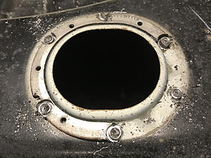
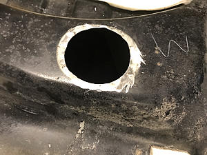
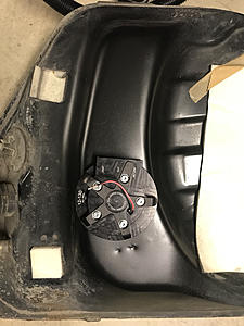
When you get to cutting the hoses, the wording in the instructions was a little odd and confusing. The 12-130 kit is designed for a max tank depth of 12" and the hoses are cut with exactly that in mind. If you need them shorter, in our case 9.75", you subtract that from 12" and cut off the remainder, 2.25" from the two hoses and the support bar. Then assemble everything. That may seem simple but if you are reading the instructions it is as if they are telling you to cut the hoses to 2.25".
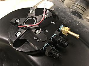
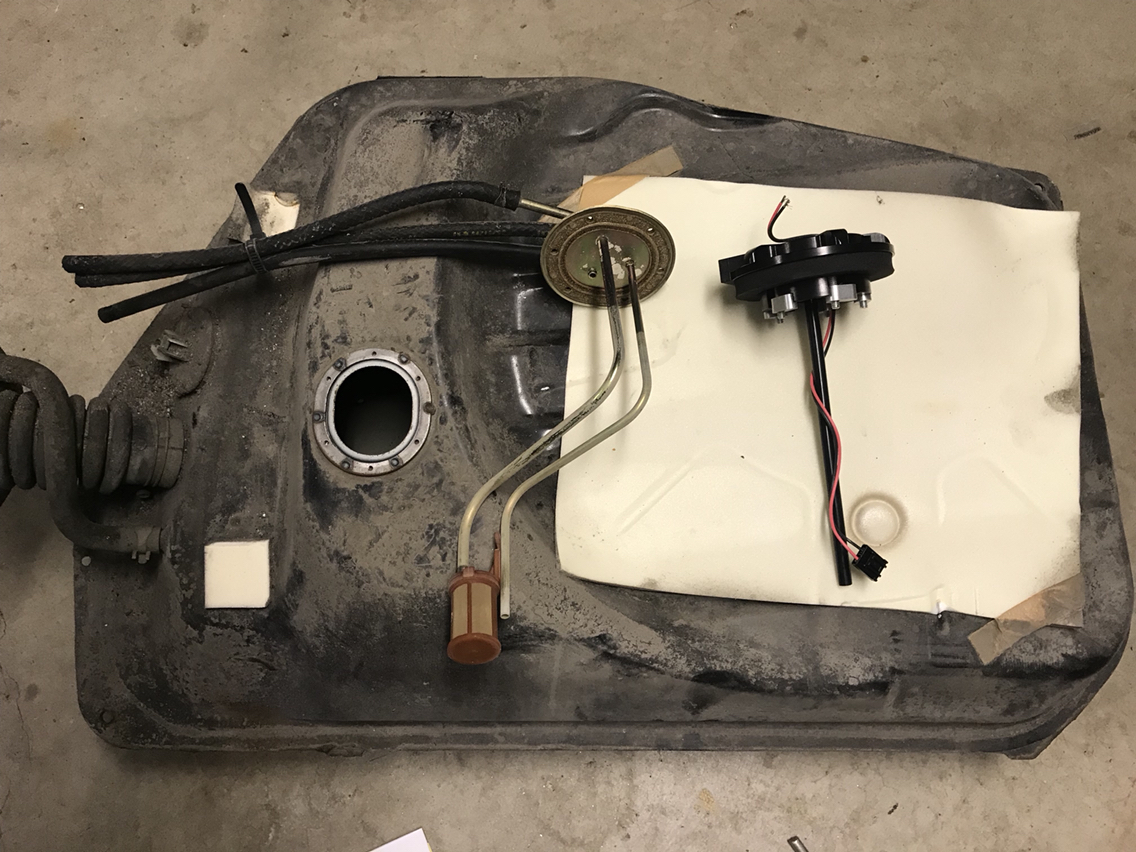
Anyway, the kit fits great and I hoisted the tank back up to make sure it clears everything. The hydramat needs to be angled slightly to avoid the fuel level sender, but it will still reach the front of the tank. It may not pickup every last ounce of fuel but it's going to come close. It'll work better with the GSL tank since there is no cup on the floor of the tank to get in the way.
Fittings are 1/4" NPT and no one sells a black 1/4" NPT to 1/4" hose that I could find, so I ended up with a brass one. Oh well, it's going to be under the car anyway!


When you get to cutting the hoses, the wording in the instructions was a little odd and confusing. The 12-130 kit is designed for a max tank depth of 12" and the hoses are cut with exactly that in mind. If you need them shorter, in our case 9.75", you subtract that from 12" and cut off the remainder, 2.25" from the two hoses and the support bar. Then assemble everything. That may seem simple but if you are reading the instructions it is as if they are telling you to cut the hoses to 2.25".
Anyway, the kit fits great and I hoisted the tank back up to make sure it clears everything. The hydramat needs to be angled slightly to avoid the fuel level sender, but it will still reach the front of the tank. It may not pickup every last ounce of fuel but it's going to come close. It'll work better with the GSL tank since there is no cup on the floor of the tank to get in the way.
Fittings are 1/4" NPT and no one sells a black 1/4" NPT to 1/4" hose that I could find, so I ended up with a brass one. Oh well, it's going to be under the car anyway!
02-16-19, 10:26 AM
#38
ancient wizard...
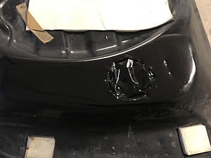
Looking good! Clean setup,i prefer to use pipe dope as you have here. Teflon tape works,but pipe dope guarantees no stray pieces of tape getting somewhere not wanted.
I like the fact the pump head AND lines protrude less than an inch above top of tank. This would be beneficial to my truck tank pump install,but concerned about mounting lugs eventually deforming poly tank in truck and causing a leak.
What does the pump kit come with regarding pickup sock?
I like the fact the pump head AND lines protrude less than an inch above top of tank. This would be beneficial to my truck tank pump install,but concerned about mounting lugs eventually deforming poly tank in truck and causing a leak.
What does the pump kit come with regarding pickup sock?
02-16-19, 01:45 PM
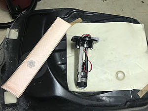
#39
The long pad in one of the photos above is the hydramat pickup. It can be angled so it doesn't interfere with the fuel level float. They also sell a cheaper kit that has a basic pickup sock but that won't get to the lowest part of the tank.
I always use this stuff on NPT threads. Brush it on and there is no chance of leaking. Says right on the can it is safe for gasoline.
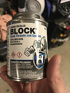
I always use this stuff on NPT threads. Brush it on and there is no chance of leaking. Says right on the can it is safe for gasoline.


Thread
Thread Starter
Forum
Replies
Last Post
rotarypower101
Single Turbo RX-7's
6
08-21-07 01:31 AM
palsor1
3rd Generation Specific (1993-2002)
2
11-10-06 09:37 AM