
1984 GSL-SE S4 13b Project

Thread Starter
Joined: Jun 2003
Posts: 832
Likes: 11
From: Northern California
1984 GSL-SE S4 13b Project
It's a been about two years since I got the car, just thought I'd share it with you guys. Whether you care or not is up to you. I just want to share any information I can about the S4 13B swap into the GSL-SE. So this thread is to show my progress and also to answer any questions if I can. I got most of my information from threads written or commented in by Steve with the 84 TII swapped GS (steve84GS TII). Be sure to buy or download a Factory service manual, they have much more thorough wiring diagrams than a Haynes etc. Here are some links to save some search time.
https://www.rx7club.com/showpost.php...98&postcount=8
https://www.rx7club.com/1st-generation-specific-1979-1985-18/s4-engine-swap-relay-questions-732204/
All the wiring advice I have gotten from those two threads and my FSM.
Here are some current pics of the progress
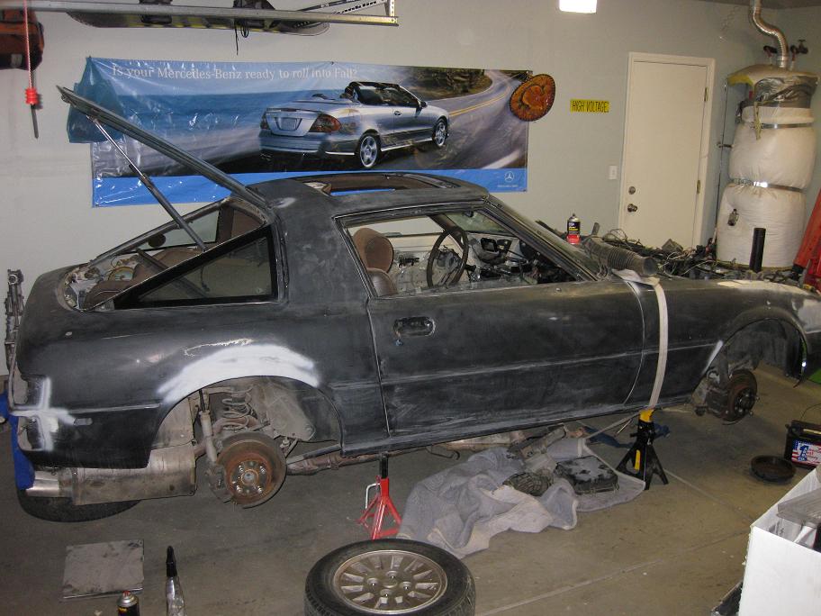
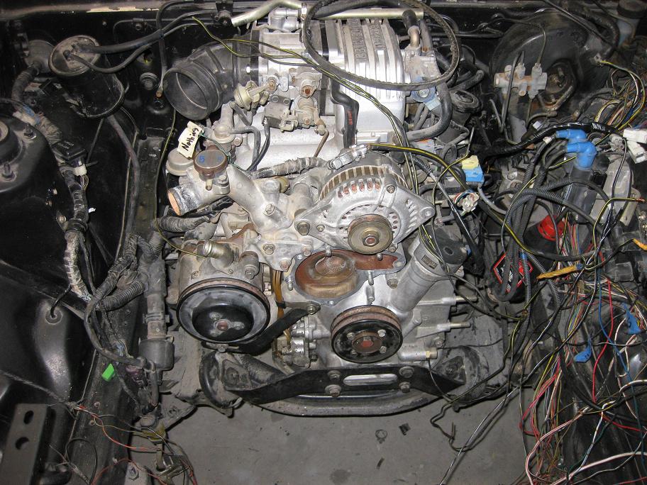
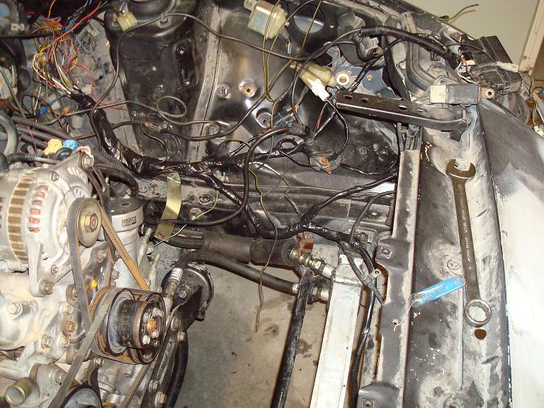
The Wiring can be daunting but if you know how to read a wiring diagram effectively you can work through it at your own pace I'm sure some of the unraveling of harness' was excessive but I wanted to remove (for the most part) wires that were no longer necessary.
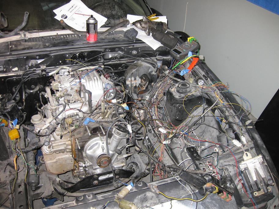
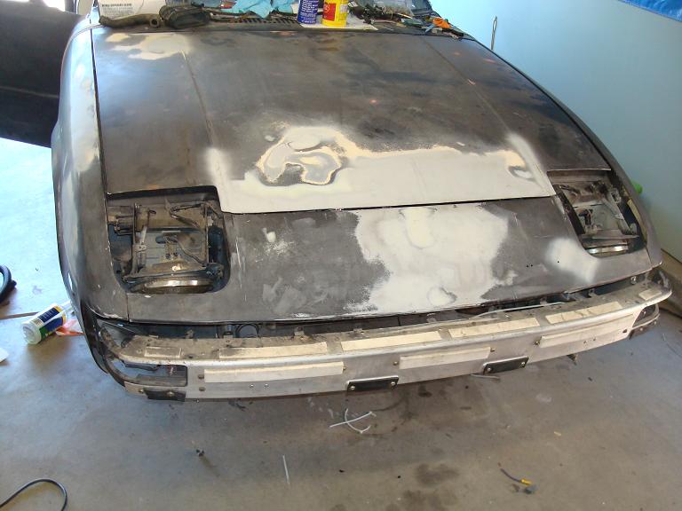
Also here you can really see why you need a GSL-SE front cover, seeing that the bracket for the motor mounts bolts directly to it, where-as the 2nd gen mounts are on the side of the rotor housing and through the oil pan.

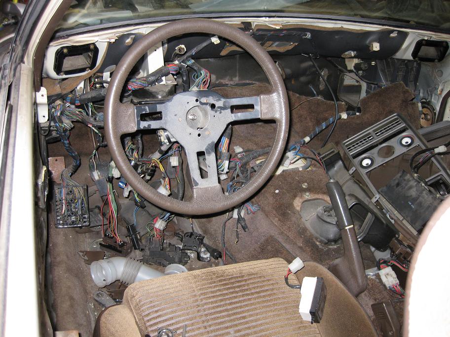
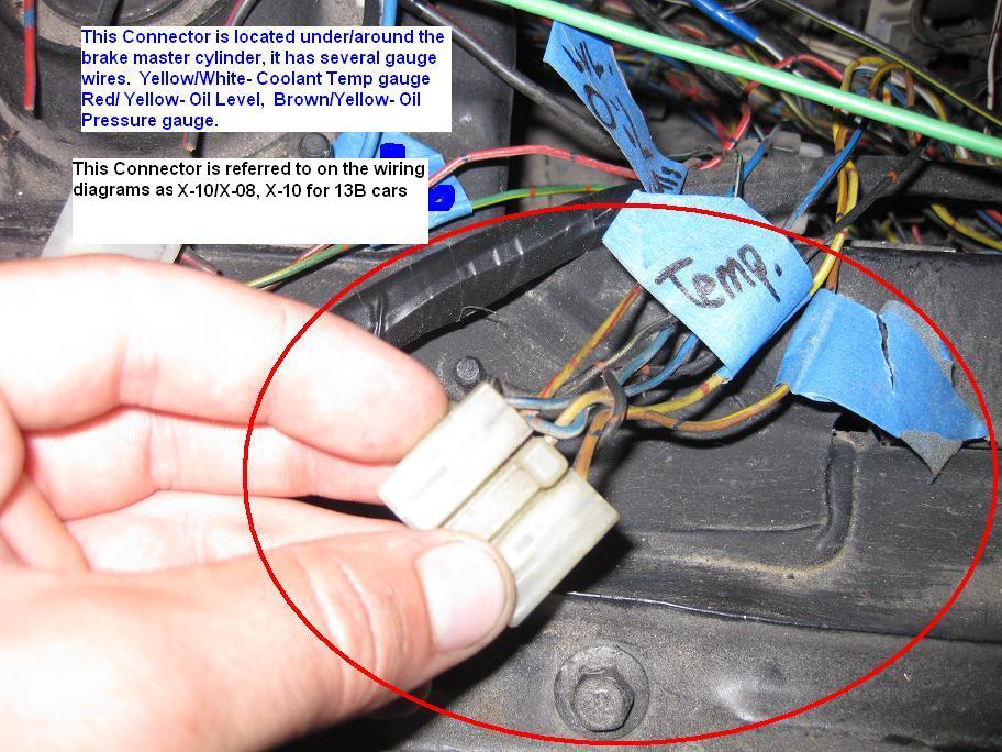
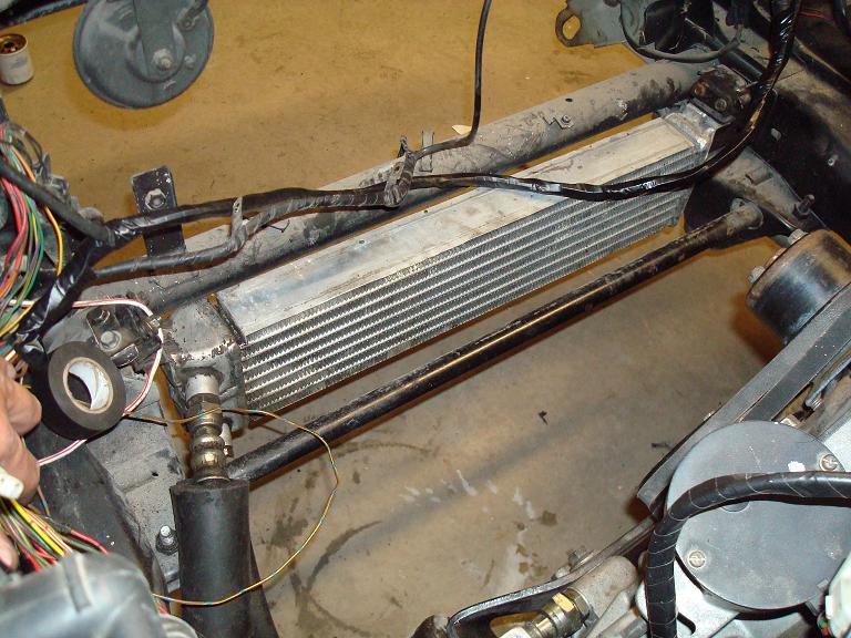
A digital multi-meter or ohm meter is essential for doing wiring, allows you to check from the instrument cluster to the engine bay to find out just what wire carries the signal to the cluster, if you are unsure or just want to double check based on what you have seen from the wiring diagrams. By attaching one lead at one end and another lead at the other end you can check the continuity of that wire to make sure that whatever signal is sent down that path, reaches it's destination. If you look to the right amongst the loose wires you'll see a section that is wrapped up. These are all the wires that travel from the 2nd gen ecu in the passenger floor board under the dash to the driver side of the engine. This includes your coil wiring, data code checker wiring, sensor wiring, and a few others.
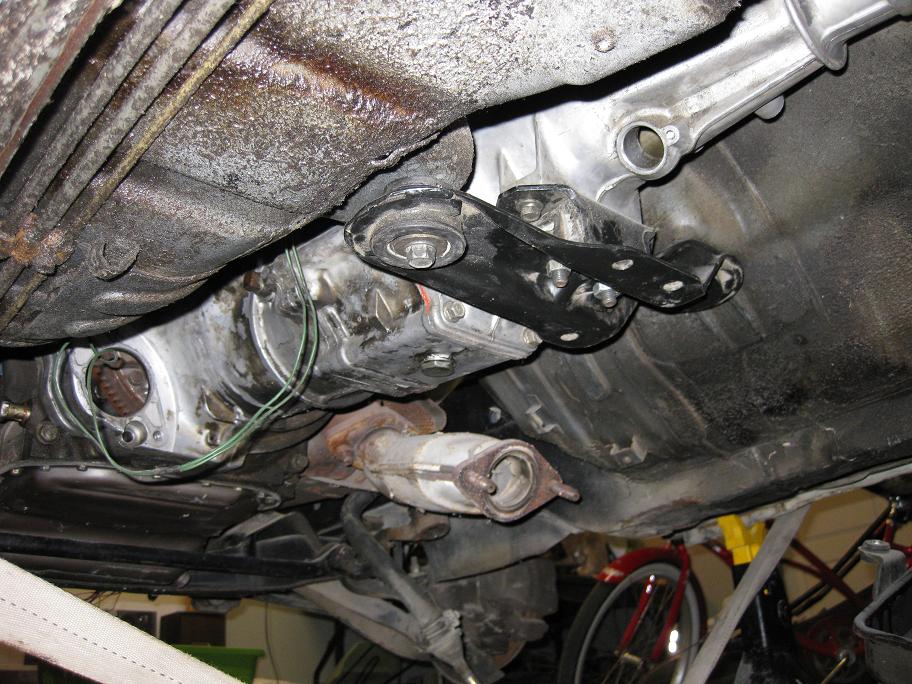
Here you can see the swap's "Hybrid Transmission" 2nd gen gearbox with 1st gen GSL-SE tail shaft housing, allows for proper mounting and shifter placement in the 1st gen chassis. Also the empty hole you see towards the rear is for the speedometer cable, when swapping the tail shaft you also have to swap in the speedometer gear from the 1st gen transmission into the 2nd gen tranny.
https://www.rx7club.com/showpost.php...98&postcount=8
https://www.rx7club.com/1st-generation-specific-1979-1985-18/s4-engine-swap-relay-questions-732204/
All the wiring advice I have gotten from those two threads and my FSM.
Here are some current pics of the progress
The Wiring can be daunting but if you know how to read a wiring diagram effectively you can work through it at your own pace I'm sure some of the unraveling of harness' was excessive but I wanted to remove (for the most part) wires that were no longer necessary.
Also here you can really see why you need a GSL-SE front cover, seeing that the bracket for the motor mounts bolts directly to it, where-as the 2nd gen mounts are on the side of the rotor housing and through the oil pan.
A digital multi-meter or ohm meter is essential for doing wiring, allows you to check from the instrument cluster to the engine bay to find out just what wire carries the signal to the cluster, if you are unsure or just want to double check based on what you have seen from the wiring diagrams. By attaching one lead at one end and another lead at the other end you can check the continuity of that wire to make sure that whatever signal is sent down that path, reaches it's destination. If you look to the right amongst the loose wires you'll see a section that is wrapped up. These are all the wires that travel from the 2nd gen ecu in the passenger floor board under the dash to the driver side of the engine. This includes your coil wiring, data code checker wiring, sensor wiring, and a few others.
Here you can see the swap's "Hybrid Transmission" 2nd gen gearbox with 1st gen GSL-SE tail shaft housing, allows for proper mounting and shifter placement in the 1st gen chassis. Also the empty hole you see towards the rear is for the speedometer cable, when swapping the tail shaft you also have to swap in the speedometer gear from the 1st gen transmission into the 2nd gen tranny.

 looking good!
Thread Starter
Joined: Jun 2003
Posts: 832
Likes: 11
From: Northern California
Thanks, I haven't really done much since the last update, just installed the heat shield. Realizing I need to get the exhaust shortened just a bit on the secondary cat. The flanges are different size from the 1st gen exhaust to the primary cat. The 2nd gen has a slightly larger exhaust.
I have the 2nd gen primary and secondary cat but a 1st gen Main cat. The main cat from my 2nd gen donor is long gone.
I have the 2nd gen primary and secondary cat but a 1st gen Main cat. The main cat from my 2nd gen donor is long gone.
Trending Topics
Thread Starter
Joined: Jun 2003
Posts: 832
Likes: 11
From: Northern California
Been on vacation and working on the car a bit, so here's a lil update.


The Black/Green wire near the thermostat housing doesn't connect to anything on an S4 N/A 13b in case you forgot like me.
The Black/Green wire near the thermostat housing doesn't connect to anything on an S4 N/A 13b in case you forgot like me.
Thread Starter
Joined: Jun 2003
Posts: 832
Likes: 11
From: Northern California
AFTER quite a bit of work, sweat, and patience we (My friend Mervin and I) got it to the point where we could temporarily connect a few things to start it up and I am very happy to say:
Got it started up for the first time!
http://www.youtube.com/watch?v=lAQVq7U4SUU
It is far from being finished, but it is nice to get a little results out of so much time and effort. Must give thanks to Steve84GS TII, without his posts/knowledge I'd be lost.
Got it started up for the first time!
http://www.youtube.com/watch?v=lAQVq7U4SUU
It is far from being finished, but it is nice to get a little results out of so much time and effort. Must give thanks to Steve84GS TII, without his posts/knowledge I'd be lost.


excellent progress here. keep us updated. i fully understand how tough this can be. i converted an 85 GS to fuel injection using a GSL-SE engine. its all oem SE stuff form the tank to the oil cooler. i had to custom make fuel lines and pull the dash and replace the harness and probe witha mulitmeter..took a couple months to finish. its my rolling restoration.
Thread Starter
Joined: Jun 2003
Posts: 832
Likes: 11
From: Northern California
First off the Circuit opening relay.
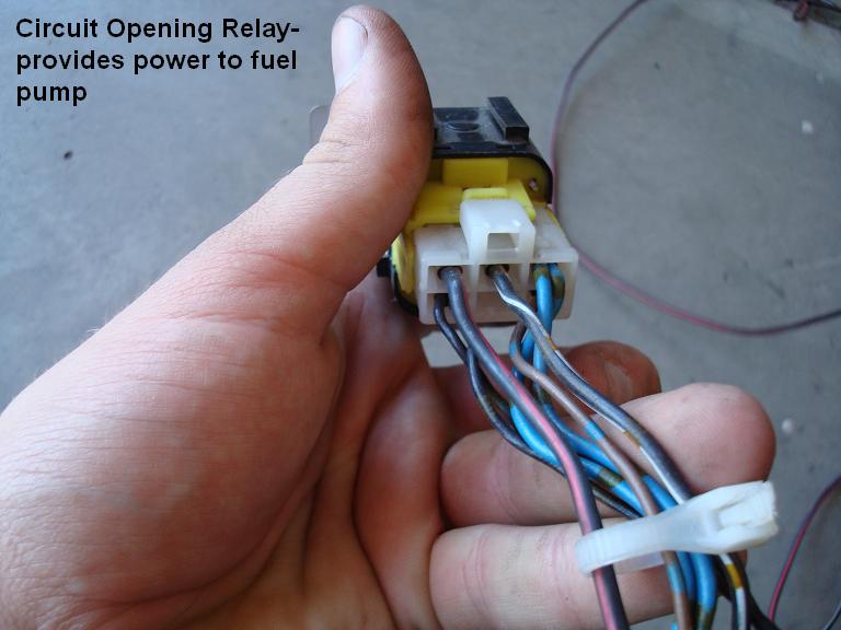
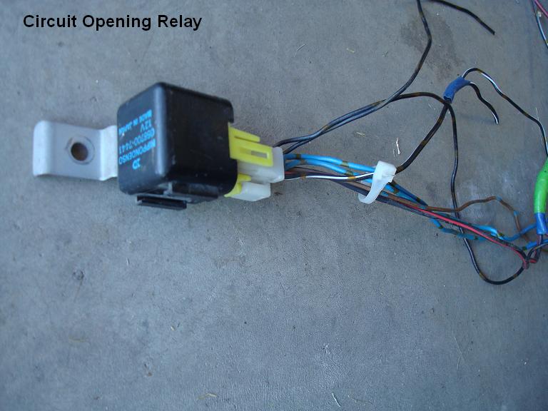
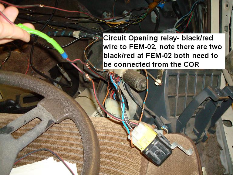
Circuit Opening Relay (COR)
On an FC this relay is found under the dash on the DRIVER side. It is black and yellow with a white connector. In a GSL-SE this relay is found next to the ECU in the passenger floor board area. There are five pins on this connector, they are as follows:
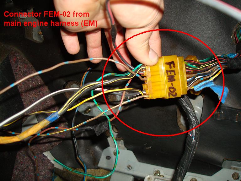
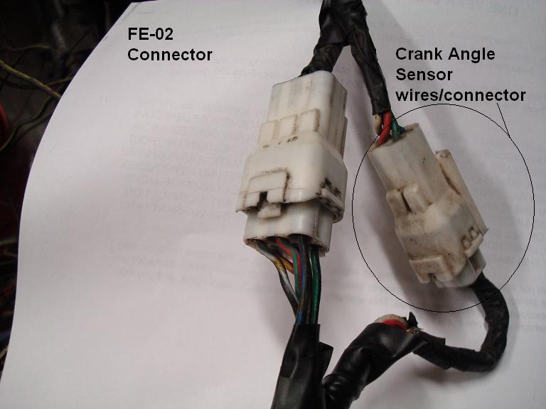
Brown- This Wire should connect to the brown wire at the FEM-02 connector off of the main engine harness, the signal from this wire comes from your MASS AIR FLOW SENSOR. When air is drawn past the MAF door while cranking it triggers so that you can have fuel when cranking.
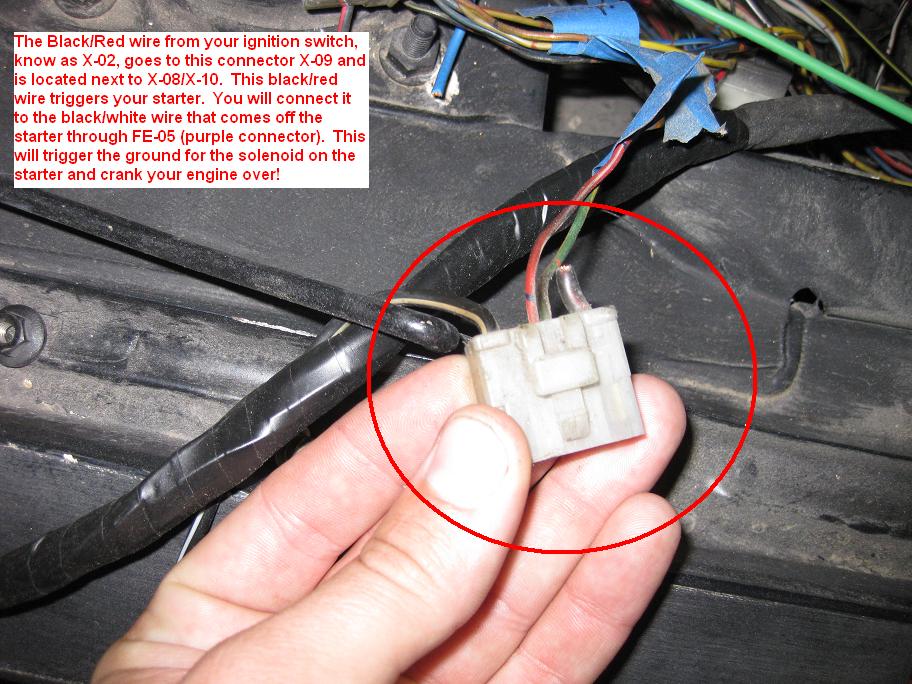
Black/Red- This needs to be connected to the same wire you hook up for your starter from ignition switch aka Starter Power. This allows there to be power even when cranking.
Blue- is the wire that carries power to the actual fuel pump
Black/White- is ignition source 1 power
Black-Ground, of course.
The Circuit Opening Relay can be found on pages 50-28 and 50-36 of the 2nd gen factory manual.
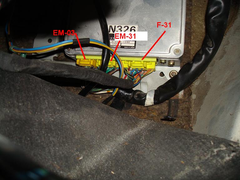
If you are doing the S4 swap into a GSL-SE, you can use the COR connector that is already in the passenger floor board area. You will have to cut the brown wire and connect it to FEM-02 brown wire. You will also need to cut the Black with red and run a splice to the FEM-02 connector. There are two black/red wires at the FEM-02, both need to be connected to this red/black wire. Black/Red wire will end up at ecu pins 3D and 3B on connector EM-03 (the smallest ECU connector).
Pictures because everybody loves those!
Circuit Opening Relay (COR)
On an FC this relay is found under the dash on the DRIVER side. It is black and yellow with a white connector. In a GSL-SE this relay is found next to the ECU in the passenger floor board area. There are five pins on this connector, they are as follows:
Brown- This Wire should connect to the brown wire at the FEM-02 connector off of the main engine harness, the signal from this wire comes from your MASS AIR FLOW SENSOR. When air is drawn past the MAF door while cranking it triggers so that you can have fuel when cranking.
Black/Red- This needs to be connected to the same wire you hook up for your starter from ignition switch aka Starter Power. This allows there to be power even when cranking.
Blue- is the wire that carries power to the actual fuel pump
Black/White- is ignition source 1 power
Black-Ground, of course.
The Circuit Opening Relay can be found on pages 50-28 and 50-36 of the 2nd gen factory manual.
If you are doing the S4 swap into a GSL-SE, you can use the COR connector that is already in the passenger floor board area. You will have to cut the brown wire and connect it to FEM-02 brown wire. You will also need to cut the Black with red and run a splice to the FEM-02 connector. There are two black/red wires at the FEM-02, both need to be connected to this red/black wire. Black/Red wire will end up at ecu pins 3D and 3B on connector EM-03 (the smallest ECU connector).
Pictures because everybody loves those!
Thread Starter
Joined: Jun 2003
Posts: 832
Likes: 11
From: Northern California
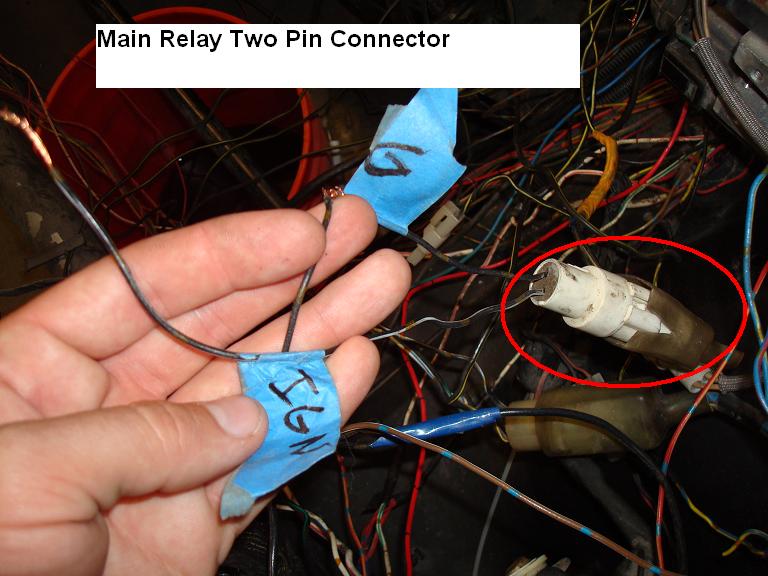
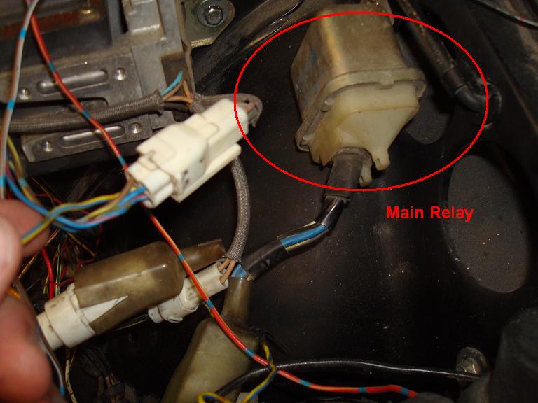
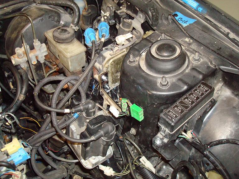
Main Relay Wiring
This relay is gold in color and has two connectors coming off of it. A Four pin and a two pin connector. On an FC this can be found next to the brake fluid reservoir on the driver side. Can be found on pages 50-31 and 50-28:
Black/White- Needs ignition source 1 power
Black- Ground
Four wires on the other Connector:
Black/Green- Battery Power from Main Fuse box
White/Blue- Battery Power from Main Fuse box
Black/White- Connects to FEM-02, which carries power to the Air Bypass Solenoid. You will need to splice this wire, one goes to FEM-02 the other goes to the Air Bypass Relay.
Black/Yellow-Connect to FEM-02 and trailing coil two pin connector. Almost all the black/yellow wires will need this. There are a few others, including one black/yellow wire that is wrapped up in the 1st gen harness.
Pictures
Thread Starter
Joined: Jun 2003
Posts: 832
Likes: 11
From: Northern California
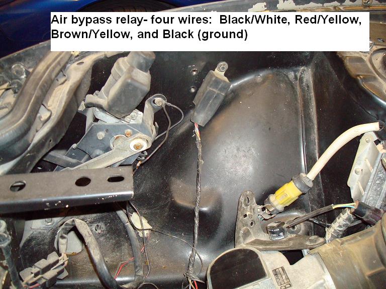
Air Bypass Relay
Can be found in an FC in the right front of the engine bay under the intake box. The air bypass relay controls the air bypass SOLENOID, which determines where the air from the air pump flows. Either to the main catalytic converter or out the dump tube when air injection isn't needed. It has a four pin connector and needs to be wired as follows:
Page 50-31 of the 2nd Gen Factory Wiring Diagram
Black/White- Power From Main relay four pin connector
Red/Yellow To ECU pin C on connector F31 (F) left side harness (the one you are making)
Brown/Yellow- Connect to brown yellow on FEM-02 from (F) left harness
Black-Ground
In the last picture you can see the brown yellow wire from the FEM-02 connector, that is the one you need to connect to the air bypass relay brown/yellow wire.
Pictures
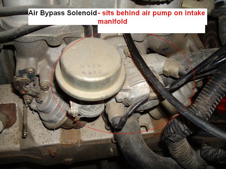
Thread Starter
Joined: Jun 2003
Posts: 832
Likes: 11
From: Northern California
Trailing and Leading Coil Wiring
Trailing and Leading coils can be found on the driver side of the engine bay of an FC.
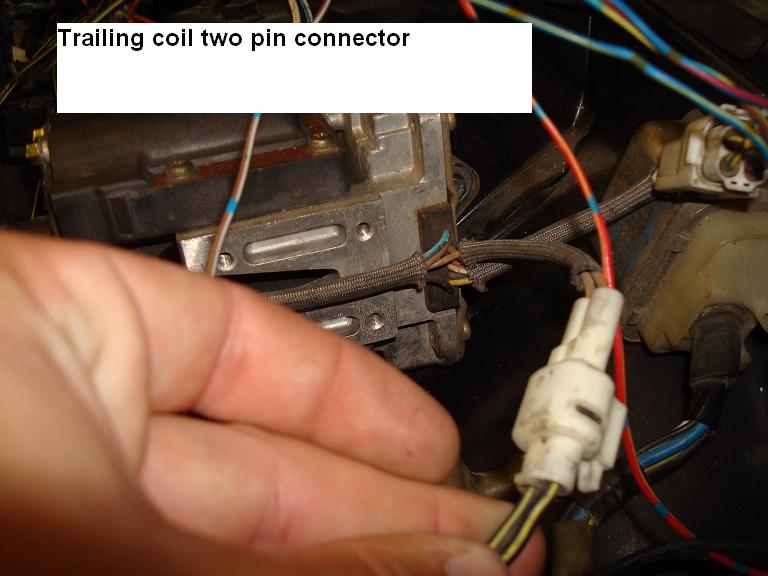
We'll start with the trailing coil, it has two connectors:
Two Pin Connector (simple!):
Black/Yellow- Connect to black/yellow from main relay
Black/Yellow- Connect to black/yellow from main relay
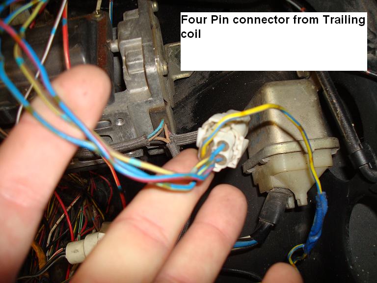
Four Pin Connector:
Blue/Yellow- Part of your (F) or left side harness you are fabricating, goes to pin X on F-31 ECU Connector
Brown/Yellow-Part of your (F) or left side harness you are fabricating, goes to pin U on F-31 ECU Connector
Blue/Red- Part of your (F) or left side harness you are fabricating, goes to pin M on F-31 ECU Connector
Yellow/Blue- Goes to your Tachometer (RPM signal for your Gauge) AND the green check connector F39
Leading Coil
Two Pin Connector:
Black/Yellow- Connect to main relay power the black/yellow wire, also t's off to a small black box called a condenser
Green/Yellow-Part of your (F) or left side harness you are fabricating, goes to pin V on F-31 ECU Connector
There is also a single black wire with a connector on it the comes off the leading coil, DO NOT GROUND THIS! Just leave it be.
Trailing and Leading coils can be found on the driver side of the engine bay of an FC.
We'll start with the trailing coil, it has two connectors:
Two Pin Connector (simple!):
Black/Yellow- Connect to black/yellow from main relay
Black/Yellow- Connect to black/yellow from main relay
Four Pin Connector:
Blue/Yellow- Part of your (F) or left side harness you are fabricating, goes to pin X on F-31 ECU Connector
Brown/Yellow-Part of your (F) or left side harness you are fabricating, goes to pin U on F-31 ECU Connector
Blue/Red- Part of your (F) or left side harness you are fabricating, goes to pin M on F-31 ECU Connector
Yellow/Blue- Goes to your Tachometer (RPM signal for your Gauge) AND the green check connector F39
Leading Coil
Two Pin Connector:
Black/Yellow- Connect to main relay power the black/yellow wire, also t's off to a small black box called a condenser
Green/Yellow-Part of your (F) or left side harness you are fabricating, goes to pin V on F-31 ECU Connector
There is also a single black wire with a connector on it the comes off the leading coil, DO NOT GROUND THIS! Just leave it be.
Thread Starter
Joined: Jun 2003
Posts: 832
Likes: 11
From: Northern California
Here is the custom Trailing Coil bracket I made out of some angle steel and straight steel. Mounted to two threaded holes that were pre-existing on the driver side strut tower.
The Leading coil will be mounted close to where it sits in the picture. As you can see the harness is getting all wrapped up and NORMAL looking
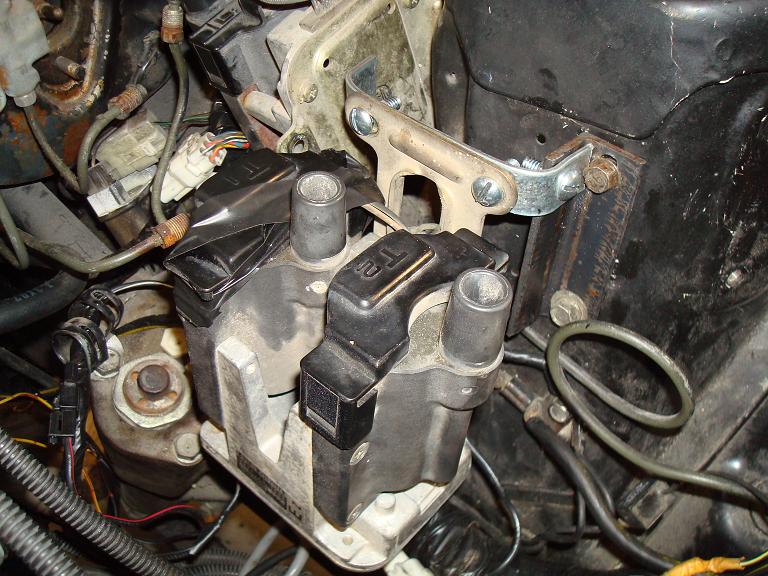
The Leading coil will be mounted close to where it sits in the picture. As you can see the harness is getting all wrapped up and NORMAL looking
Thread Starter
Joined: Jun 2003
Posts: 832
Likes: 11
From: Northern California
A video of the car starting, after fixing a few bugs it started much better. I have more wiring advice coming later. I have to make my notes and then try to write it sensibly.
ENJOY!
http://www.youtube.com/watch?v=h9OPi9PmYgs
ENJOY!
http://www.youtube.com/watch?v=h9OPi9PmYgs
Thread Starter
Joined: Jun 2003
Posts: 832
Likes: 11
From: Northern California
First off the Circuit opening relay.
Circuit Opening Relay (COR)
On an FC this relay is found under the dash on the DRIVER side. It is black and yellow with a white connector. In a GSL-SE this relay is found next to the ECU in the passenger floor board area. There are five pins on this connector, they are as follows:
Brown- This Wire should connect to the brown wire at the FEM-02 connector off of the main engine harness, the signal from this wire comes from your MASS AIR FLOW SENSOR. When air is drawn past the MAF door while cranking it triggers so that you can have fuel when cranking.
Black/Red- This needs to be connected to the same wire you hook up for your starter from ignition switch aka Starter Power. This allows there to be power even when cranking.
Blue- is the wire that carries power to the actual fuel pump
Black/White- is ignition source 1 power
Black-Ground, of course.
The Circuit Opening Relay can be found on pages 50-28 and 50-36 of the 2nd gen factory manual.
If you are doing the S4 swap into a GSL-SE, you can use the COR connector that is already in the passenger floor board area. You will have to cut the brown wire and connect it to FEM-02 brown wire. You will also need to cut the Black with red and run a splice to the FEM-02 connector. There are two black/red wires at the FEM-02, both need to be connected to this red/black wire. Black/Red wire will end up at ecu pins 3D and 3B on connector EM-03 (the smallest ECU connector).
Pictures because everybody loves those!
EDIT! Regarding the two black/red wires that run through FEM-02.
- One of the black/red wires switches to black/blue wire on the ecu side, this wire ends up at terminal 3b of ECU connector EM-03
-If you are looking on page 50-28 you will see that these wires are shown as black/white. But if you look at 50-36 (Fuel Pump and Sub-zero starting assist system) You will see the wire is marked black/white OR black/red. Just remember this when you are trying to read the diagram.
-While you are looking at page 50-28, check out pin 3J from EM-03 right next to the black/red (black/white) wires I was just mentioning. The wire from pin 3J goes through FEM-02 it is WHITE/BLUE, it receives battery power through the interior fuse box on the same circuit as the interior lights, clock, etc all things that require power with key off. It is a low amperage constant battery power to the ecu, it runs through a 7.5A fuse. As far as I can tell the car would run fine without it but when you turn the key off it will be like resetting the ECU everytime. I ran an inline fuse to battery power to this wire. Seems to work just fine.
If you look at page 50-28 of the wiring diagram, you'll see it shows white/blue from the ecu to FEM-02 and then it is blue/red from FEM-02 to battery power source 9 (Int. Fuse Box). Which if you look on the power flow diagram on page 50-15 you can see the blue/red wire that comes from a 7.5amp fuse in the interior fuse box. The power goes to warning buzzers, dome lights, clock, audio system, and E.G.I emision control system.
Thread Starter
Joined: Jun 2003
Posts: 832
Likes: 11
From: Northern California
A Few pictures for you guys.
Got my FC radiator mounted, took a little trimming and banging. But it's in and the hood clears it.
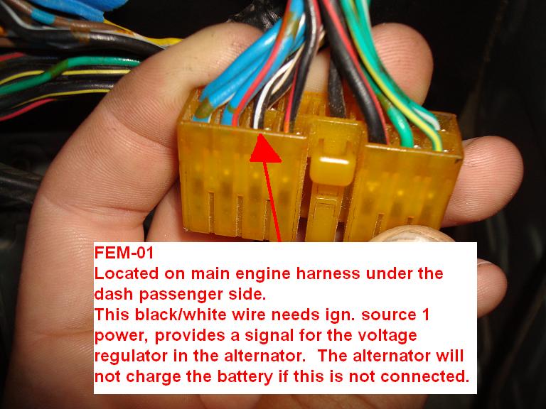
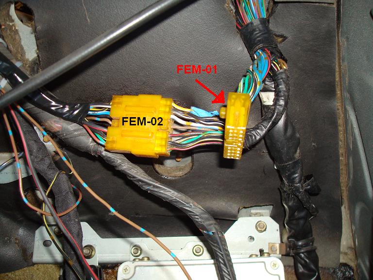
Picture of what FEM-01 looks like and the alternator wire that needs to be connected to ign. source 1.
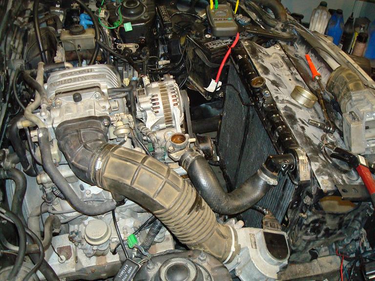
Got my FC radiator mounted, took a little trimming and banging. But it's in and the hood clears it.
Picture of what FEM-01 looks like and the alternator wire that needs to be connected to ign. source 1.
