1984 GSL-SE S4 13b Project

 08-18-09, 11:08 PM
#27
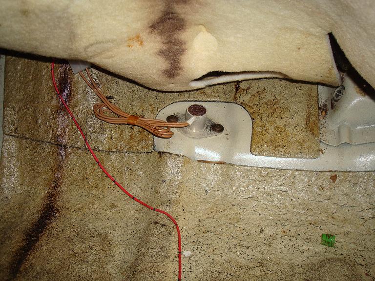
HEAT HAZARD SWITCH
You can find this one underneath the carpet under the passenger seat. So remove the seat to get to it, or if your car doesn't have one already then you'll need to install it here seeing as it sits on the floor near where the Main catalyst will be making all that heat.
The diagram shows the wire to be red/black, but my wire in the car is red/yellow for the 1st gen. In a 2nd gen the wire colors are black and black/yellow. Black being the ground and black/yellow the signal to the idiot lights and the ecu.
Two Pin connector
Black- Ground
(GSL/SE)Red/yellow- To ECU via your left side harness Black/Yellow wire this signal also goes to the heat hazard warning light.
Make sure the signal wire that goes to your ecu isn't grounded, or the Air pump will constantly pump air out the dump tube. The switch should ground the ecu if the floor gets too hot to tell the air pump to stop feeding oxygen to your main catalyst.
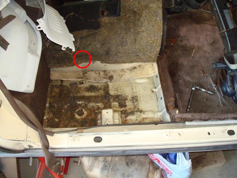
08-23-09, 11:06 PM
#29
I used the FC fuse block instead of the fusible link setup. Almost all of the wires correspond. There are a few you don't use, Like I didn't use the ECU fusible link and there was another one I couldn't read. Didn't need that either.
*Edit* I guess I should ask, are you talking about the ignition switch or Ignition Coils? I went over the ignition coil wiring on the 1st page.
*Edit* I guess I should ask, are you talking about the ignition switch or Ignition Coils? I went over the ignition coil wiring on the 1st page.
08-24-09, 12:19 AM
#30
Junior Member

Join Date: Aug 2009
Location: Norman
Posts: 8
Likes: 0
Received 0 Likes
on
0 Posts
I think I've been too close to the project too long. Got the fuse box wired up as if it was a link. Working the way I want now.
I did have a question about the circuit opening relay Why not use the setup that the car is running. I have yet to put the COR on and I am getting fuel, unless the relay allows for fuel flow while cranking unlike the stock setup???
Thanks for the quick reply and all the other help you've supplied me with.
08-24-09, 11:26 AM
#31
The GSL-SE has a circuit opening relay already, you just have to give it the signal from your MAF sensor and starter power. The ignition source, fuel pump wires, and ground wires are already there. If the relay doesn't receive a signal from the MAF it will not pump fuel while cranking.
I don't know how the 12a system works, I do know you'll have to upgrade the fuel pump and possibly the lines to run the fuel injected setup though.
I don't know how the 12a system works, I do know you'll have to upgrade the fuel pump and possibly the lines to run the fuel injected setup though.
08-24-09, 10:06 PM
#35
Senior Member
iTrader: (1)
Join Date: Jan 2004
Location: Albany, OR
Posts: 358
Likes: 0
Received 0 Likes
on
0 Posts
Wow, this seams like so much work. I am totally lost on all this wiring stuff. I have only done basic wiring work on cars. Do you enjoy doing work like this or are the benefits of the S4 engine over the GSL-SE engine that great? It seems like it might be easier just to get an aftermarket ECU instead of doing all the splicing into the factory wiring. I'm not judging but I would like to know what inspired you to do this.
08-24-09, 11:01 PM
#36
Senior Member
iTrader: (4)

Join Date: Mar 2003
Location: Bay Area, Ca
Posts: 273
Likes: 0
Received 0 Likes
on
0 Posts
Wow, this seams like so much work. I am totally lost on all this wiring stuff. I have only done basic wiring work on cars. Do you enjoy doing work like this or are the benefits of the S4 engine over the GSL-SE engine that great? It seems like it might be easier just to get an aftermarket ECU instead of doing all the splicing into the factory wiring. I'm not judging but I would like to know what inspired you to do this.
08-25-09, 12:37 AM
#37
I had an entire 2nd gen Rx7 sitting around and the GSL-SE engine was blown (bad oil seal), So I figured why not. The wiring really isn't THAT difficult. The S4 into gsl-se swap is considered the easiest swap.
Like Irish said, cost was one factor. I already had the donor car and I would rather do a swap and upgrade than rebuild the old motor. It has low miles and ran really well in my FC before it got totalled.
I do enjoy project cars and this one I believe will definitely be worth it when it's done. Not to mention I see posts ALL the time asking about S4/S5 swaps into 1st gen chassis, figured I could help someone out.
08-25-09, 12:47 AM
#38
Carbureted engines use low fuel pressure, I believe just to fill the float bowl. Engine vacuum is then used to draw fuel in, so the car has to be cranking for the fuel to actually "inject" into the intake stream. My guess with the EFI setup is that they want the fuel to have some place to go, thus avoiding putting a huge strain on the High pressure fuel pump.
It would be a good Idea to run the Circuit Opening relay for this reason. If your fuel pump is running at all times the ignition power is on then your pump will be over stressed.
08-25-09, 09:59 PM
#39
FB=OS Giken LSD
iTrader: (20)
Join Date: Apr 2001
Location: Wilmington, DE
Posts: 2,279
Likes: 0
Received 0 Likes
on
0 Posts
Hey, I am very interested in the hybred tranny setup that you did. Are there any tricks to this? Do they just bolt up? Will this simply bolt into your FB once together? I happen to have my original blown tranny sitting next to my S4 tranny that is going in and I would prefer to go your route over the custom mount and drive shaft.
Any info is much appreciated. Thanks!
Any info is much appreciated. Thanks!
08-26-09, 09:14 AM
#41
FB=OS Giken LSD
iTrader: (20)
Join Date: Apr 2001
Location: Wilmington, DE
Posts: 2,279
Likes: 0
Received 0 Likes
on
0 Posts
Thanks! You just saved me a couple hundred $ and some hearaches. It looks like you used the red RTV to put them together. Torque specs? I will do this tonight.
08-26-09, 10:44 AM
#42
Also make sure you use the 1st gen shift rod as the second gen one will be too long. Be sure to get your shift rod in the right place before you glue the case back together. I had to do mine over because it wouldn't shift.
08-26-09, 11:11 AM
#43
FB=OS Giken LSD
iTrader: (20)
Join Date: Apr 2001
Location: Wilmington, DE
Posts: 2,279
Likes: 0
Received 0 Likes
on
0 Posts
Will do. I am about to embark on the whole engine swap over the next few weeks and these kind of threads are priceless. Thanks!
I do feel for you with that swap though. Here in Philadelphia, my car is old enough to register as an antique so no more state or emmissions for me. I have a pre-terminated harness for my microtech so hopefully it will be mainly plug and play.
I do feel for you with that swap though. Here in Philadelphia, my car is old enough to register as an antique so no more state or emmissions for me. I have a pre-terminated harness for my microtech so hopefully it will be mainly plug and play.
 08-28-09, 12:39 AM
#49
FEM-01 and 02 don't have anything to do with spark, so if you aren't getting spark look elsewhere.
FEM-01
Black/white wire- requires ign. source 1 voltage, this is a signal to your alternator.
FEM-02
There should be 2 of these. One is Black/Red OR Black/white on the front harness side and becomes black/blue, The b/r or b/w side should connect to the black/red wire from your circuit opening relay. All 3 wires, the 2 that go through FEM-02 and the Circuit opening relay should all get starter power.
FROM THE AIR BYPASS RELAY
Brown/Yellow- Connect to brown yellow on FEM-02 from (F) left harness
FROM THE MAIN RELAY
Black/White- Connects to FEM-02, which carries power to the Air Bypass Solenoid. You will need to splice this wire, one goes to FEM-02 the other goes to the Air Bypass Relay.
Black/Yellow-Connect to FEM-02 and trailing coil two pin connector. Almost all the black/yellow wires will need this. There are a few others, including one black/yellow wire that is wrapped up in the 1st gen harness.
FROM THE CIRCUIT OPENING RELAY
Brown- This Wire should connect to the brown wire at the FEM-02 connector off of the main engine harness, the signal from this wire comes from your MASS AIR FLOW SENSOR. When air is drawn past the MAF door while cranking it triggers so that you can have fuel when cranking.
My car started without this BUT, started better after I connected it
-While you are looking at page 50-28, check out pin 3J from EM-03 right next to the black/red (black/white) wires I was just mentioning. The wire from pin 3J goes through FEM-02 it is WHITE/BLUE, it receives battery power through the interior fuse box on the same circuit as the interior lights, clock, etc all things that require power with key off. It is a low amperage constant battery power to the ecu, it runs through a 7.5A fuse. As far as I can tell the car would run fine without it but when you turn the key off it will be like resetting the ECU everytime. I ran an inline fuse to battery power to this wire. Seems to work just fine.
If you look at page 50-28 of the wiring diagram, you'll see it shows white/blue from the ecu to FEM-02 and then it is blue/red from FEM-02 to battery power source 9 (Int. Fuse Box). Which if you look on the power flow diagram on page 50-15 you can see the blue/red wire that comes from a 7.5amp fuse in the interior fuse box. The power goes to warning buzzers, dome lights, clock, audio system, and E.G.I emision control system.