Midsummer Update On My Turbo NA Bridgeport Project
 08-07-06, 10:58 AM
#1
Engine, Not Motor
Thread Starter
iTrader: (1)
Join Date: Feb 2001
Location: London, Ontario, Canada
Posts: 29,789
Likes: 0
Received 108 Likes
on
91 Posts
Midsummer Update On My Turbo NA Bridgeport Project
It's been a long winter and much has been accomplished since the last update. It's getting close to the point where the car will start for the first time in 3.5 years and for the most part the hard work is done. At this point, it's mainly assembly work with some light fabrication.
Since things are so near a major turning point, I figuerd that any latecomers to this ongoing project might want to take a look at where things started. Here's a few links to all the related threads I have posted over the last few years. If you are going to read the whole thing, set aside an hour, pour yourself a drink and find a comfortable chair...
https://www.rx7club.com/showthread.p...hreadid=144198
https://www.rx7club.com/forum/showthread.php?t=328090
https://www.rx7club.com/forum/showthread.php?t=335077
https://www.rx7club.com/2nd-generation-specific-1986-1992-17/progress-my-turbo-na-bridgeport-project-project-tina-429145/
https://www.rx7club.com/forum/showthread.php?t=468413
https://www.rx7club.com/forum/showthread.php?t=498432
Now that's over with, let's get to the good stuff.
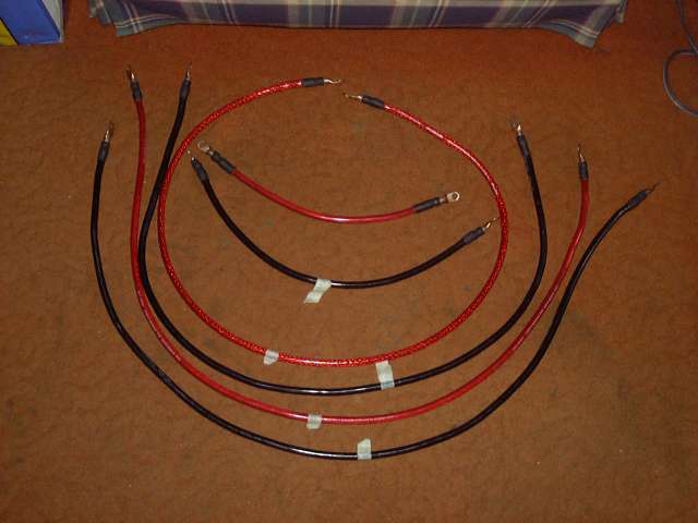
We last left off with the fabrication of the main battery and power cables. This was after the construction of an upper intake manifold from scratch, so it was a nice change to do something simple.
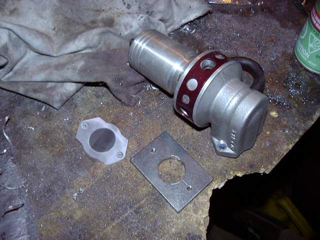
During the winter, working in the garage is less then pleasant so I tried to get as much work done inside as I could. The first little task was to make a blow off valve flange. The flange was made using 4MM thick steel. To get the pattern for the bottom of the Apex'I BOV, I scanned it into the computer and then cranked the contrast up. The resulting printout is a template that can be used to make the flange. Holes were drilled and tapped for M5 Allen head bolts.
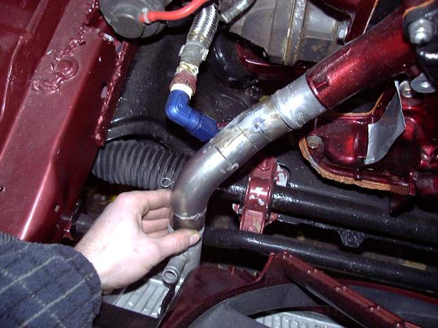
There were a few days above zero degrees so I took the opportunity to fab up the lower rad pipe. Working with pipe is fairly simple once you get the hang of visualizing the angles in your head. I like to work starting from each side and then meeting in the middle for short runs, but for longer runs you need to work from one side to the other. The tubing is 1.5" OD, with stainless weld els used to make the bends. I wanted to keep this pipe as low profile as possible to not interfere with future intercooler piping or the TID.
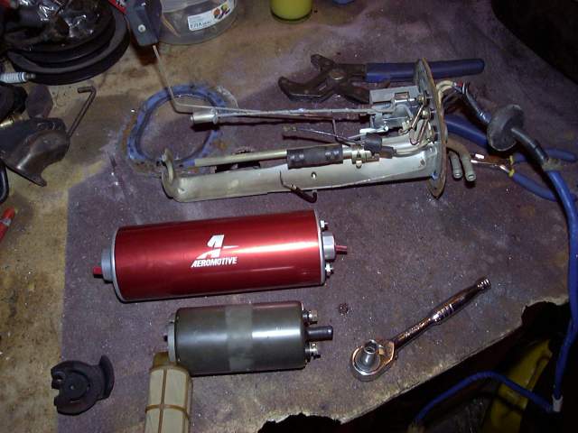
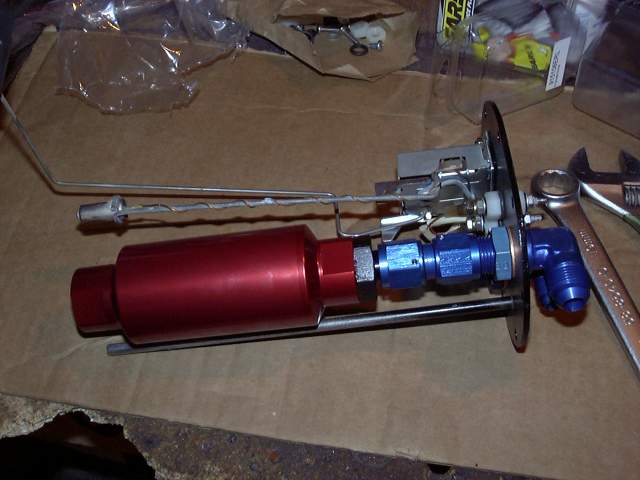
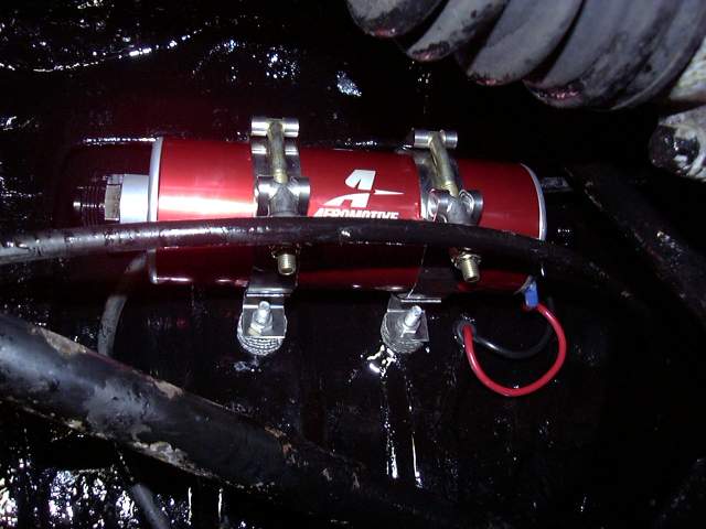
About this time, the parts for my fuel system started to come in. This is the Aeromotive A1000 pump compared to the FD pump I used previously. There's a slight difference in size so I was trying to figure out how I could mount it onto the stock tank flange. After thinking about it for a while, I gave up on that idea and decided to make a new flange.
The new flange was made by tracing the outline of the gasket onto a sheet of 12 gauge steel, and then cutting that shape out with a jigsaw. Some minor grinding on the edges finished it off and the screw holes were drilled. To feed fuel in and out of the tank I used -8 (for feed) and -6 (for return) AN bulkhead fittings. Part of the reason it was impossible to use the original stock flange was due to the size of these fittings. The picture below shows the internal tank parts being checked for fit.
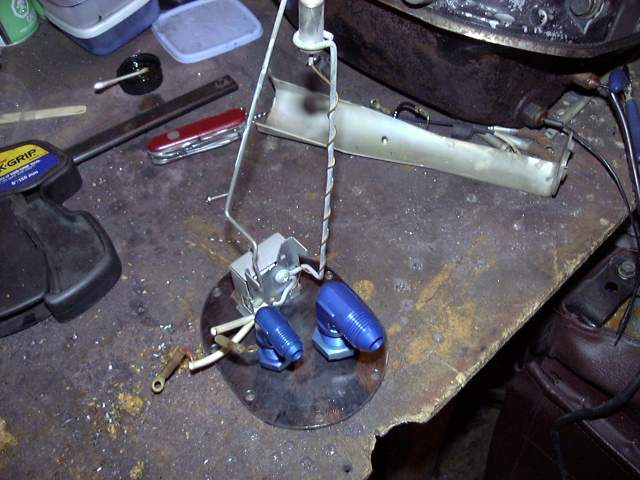
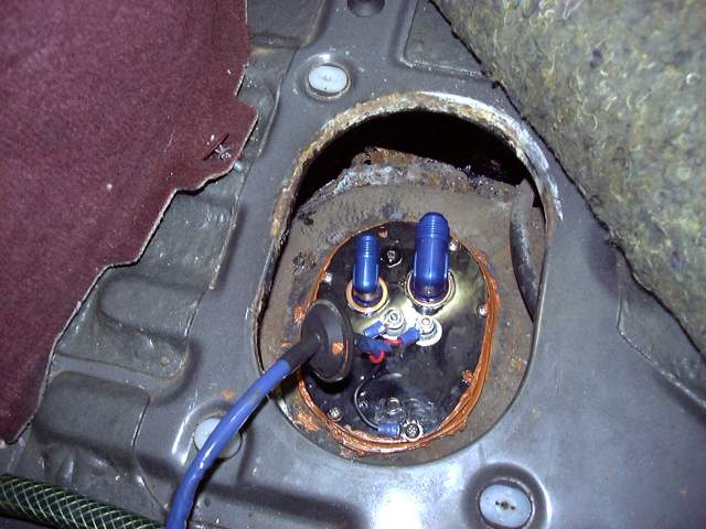
Once the positions of the fittings were known, holes were drilled and the bulkheads test fitted. Copper crush washers were used to seal things up.
The 12A in the background is a peripheral ported engine that was going to go into my GSL-SE. Since then I've decided to PP the original SE engine to make the swap marginally easier. In case you were wondering...
Since things are so near a major turning point, I figuerd that any latecomers to this ongoing project might want to take a look at where things started. Here's a few links to all the related threads I have posted over the last few years. If you are going to read the whole thing, set aside an hour, pour yourself a drink and find a comfortable chair...
https://www.rx7club.com/showthread.p...hreadid=144198
https://www.rx7club.com/forum/showthread.php?t=328090
https://www.rx7club.com/forum/showthread.php?t=335077
https://www.rx7club.com/2nd-generation-specific-1986-1992-17/progress-my-turbo-na-bridgeport-project-project-tina-429145/
https://www.rx7club.com/forum/showthread.php?t=468413
https://www.rx7club.com/forum/showthread.php?t=498432
Now that's over with, let's get to the good stuff.
We last left off with the fabrication of the main battery and power cables. This was after the construction of an upper intake manifold from scratch, so it was a nice change to do something simple.
During the winter, working in the garage is less then pleasant so I tried to get as much work done inside as I could. The first little task was to make a blow off valve flange. The flange was made using 4MM thick steel. To get the pattern for the bottom of the Apex'I BOV, I scanned it into the computer and then cranked the contrast up. The resulting printout is a template that can be used to make the flange. Holes were drilled and tapped for M5 Allen head bolts.
There were a few days above zero degrees so I took the opportunity to fab up the lower rad pipe. Working with pipe is fairly simple once you get the hang of visualizing the angles in your head. I like to work starting from each side and then meeting in the middle for short runs, but for longer runs you need to work from one side to the other. The tubing is 1.5" OD, with stainless weld els used to make the bends. I wanted to keep this pipe as low profile as possible to not interfere with future intercooler piping or the TID.
About this time, the parts for my fuel system started to come in. This is the Aeromotive A1000 pump compared to the FD pump I used previously. There's a slight difference in size so I was trying to figure out how I could mount it onto the stock tank flange. After thinking about it for a while, I gave up on that idea and decided to make a new flange.
The new flange was made by tracing the outline of the gasket onto a sheet of 12 gauge steel, and then cutting that shape out with a jigsaw. Some minor grinding on the edges finished it off and the screw holes were drilled. To feed fuel in and out of the tank I used -8 (for feed) and -6 (for return) AN bulkhead fittings. Part of the reason it was impossible to use the original stock flange was due to the size of these fittings. The picture below shows the internal tank parts being checked for fit.
Once the positions of the fittings were known, holes were drilled and the bulkheads test fitted. Copper crush washers were used to seal things up.
The 12A in the background is a peripheral ported engine that was going to go into my GSL-SE. Since then I've decided to PP the original SE engine to make the swap marginally easier. In case you were wondering...
 08-07-06, 10:58 AM
#2
Engine, Not Motor
Thread Starter
iTrader: (1)
Join Date: Feb 2001
Location: London, Ontario, Canada
Posts: 29,789
Likes: 0
Received 108 Likes
on
91 Posts
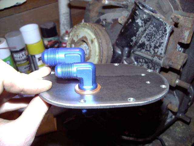
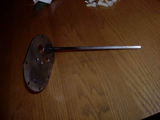
Here's the fuel tank flange all painted up, with the filter support rod welded in place.
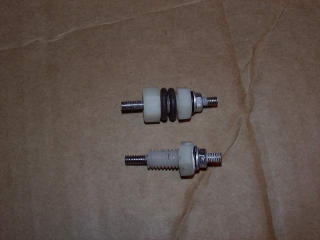
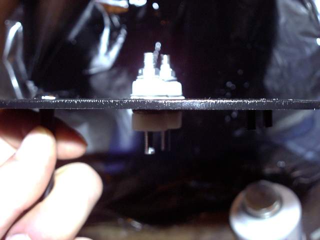
The only real issue I had with this whole adventure is figuring out a way to get the two wires for the fuel sender into the tank. I looked at various things others had done but none seemed to be ideal. It's common to just silicone the wires in place, but that would not do. Wire glands are also used, though that means that it is possible for fuel to eventually wick up inside the wire. So I went to every electrical supplier I know of to try and find small sealed bulkhead connectors but fell up short. I managed to find a picture of what I was looking for, but never the actual item.
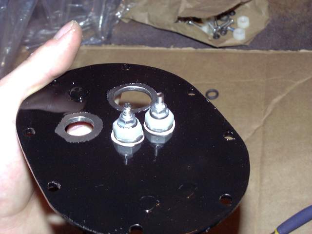
The only option left was to build my own. From the local fastener supplier I picked up some M8 nylon bolts and nuts, some M4 rod and nuts, and assorted o-rings. After drilling a hole through the center of the nylon bolt, it was tapped for M4 and the rod was threaded through it. The top was sealed with an o-ring, as was the bottom (not shown in the picture). Originally I tried to seal the bolt to the flange with the o-rings shown in the picture but that did not work out as they kept squeezing out from between the flange and bolt. So I switched to Dowty seals from the local hydraulic shop. A Dowty seal is basically a rubber o-ring encapsulated in a metal outer ring. The same type of seal is used to seal the tension bolt heads on the engine.
Here's what they look like installed with the o-rings.
And from the bottom.
The fuel level sender was then installed next. The ring terminals simply bolted onto the threaded rod passing through the nylon bolt. As you can see, Teflon sealing compound was also used. Again, those rubber o-rings were later replaced with Dowty seals. O-rings really need a machined groove to seat in otherwise they just squish out.
The only real issue I had with this whole adventure is figuring out a way to get the two wires for the fuel sender into the tank. I looked at various things others had done but none seemed to be ideal. It's common to just silicone the wires in place, but that would not do. Wire glands are also used, though that means that it is possible for fuel to eventually wick up inside the wire. So I went to every electrical supplier I know of to try and find small sealed bulkhead connectors but fell up short. I managed to find a picture of what I was looking for, but never the actual item.
The only option left was to build my own. From the local fastener supplier I picked up some M8 nylon bolts and nuts, some M4 rod and nuts, and assorted o-rings. After drilling a hole through the center of the nylon bolt, it was tapped for M4 and the rod was threaded through it. The top was sealed with an o-ring, as was the bottom (not shown in the picture). Originally I tried to seal the bolt to the flange with the o-rings shown in the picture but that did not work out as they kept squeezing out from between the flange and bolt. So I switched to Dowty seals from the local hydraulic shop. A Dowty seal is basically a rubber o-ring encapsulated in a metal outer ring. The same type of seal is used to seal the tension bolt heads on the engine.
Here's what they look like installed with the o-rings.
And from the bottom.
The fuel level sender was then installed next. The ring terminals simply bolted onto the threaded rod passing through the nylon bolt. As you can see, Teflon sealing compound was also used. Again, those rubber o-rings were later replaced with Dowty seals. O-rings really need a machined groove to seat in otherwise they just squish out.
08-07-06, 10:59 AM
#3
Engine, Not Motor
Thread Starter
iTrader: (1)
Join Date: Feb 2001
Location: London, Ontario, Canada
Posts: 29,789
Likes: 0
Received 108 Likes
on
91 Posts
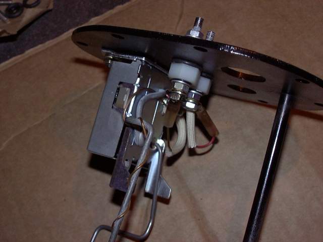
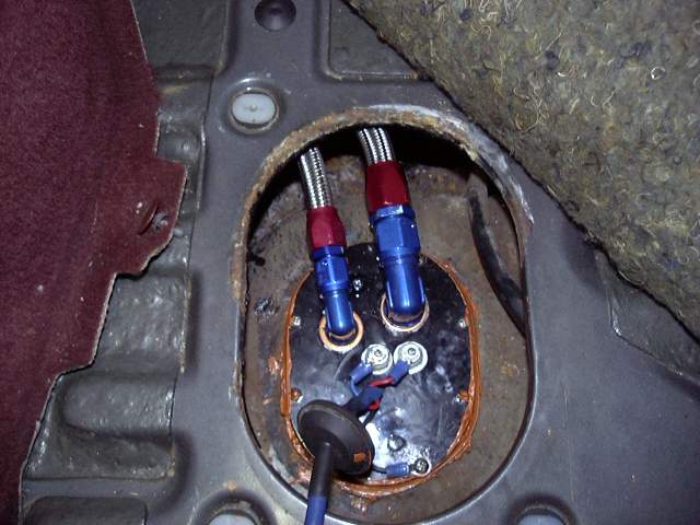
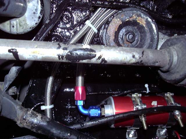
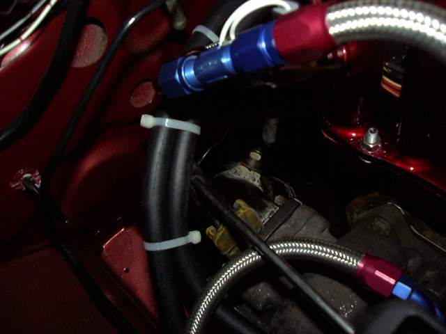
After the level sender was in place, the fuel bulkhead fittings were installed. Copper crush washers sealed them to the flange. These are aluminum bulkheads but steel bulkheads are also available which could have been welded directly to the flange. I chose not to do that since that application really calls for a TIG welder which I don't have. MIG/flux core would just make a mess of it.
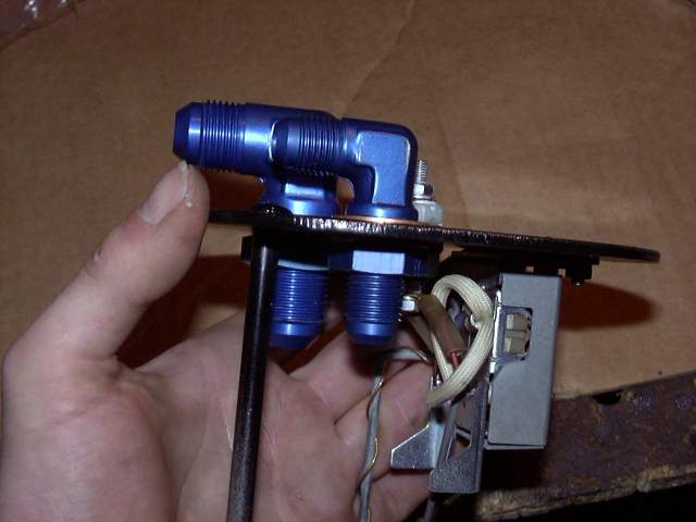
Since there was no hope of installing the large Aeromotive pump in place of the stocker, I chose to mount the pre-filter in it's place. The filter has a -10 ORB input, and a -10 ORB output. The input is left to suck fuel from the tank while a -10 ORB to -8 to flare adapter is installed on the output, and a female to female -8 adapter connects the filter to the bulkhead.
A short length of -6 braided stainless hose connects to the -6 bulkhead as a fuel return. The only worm gear style hose clamp on the entire car can be found here, holding the filter to the tank flange. A little bit of rubber fuel line hose keeps the filter from rubbing.
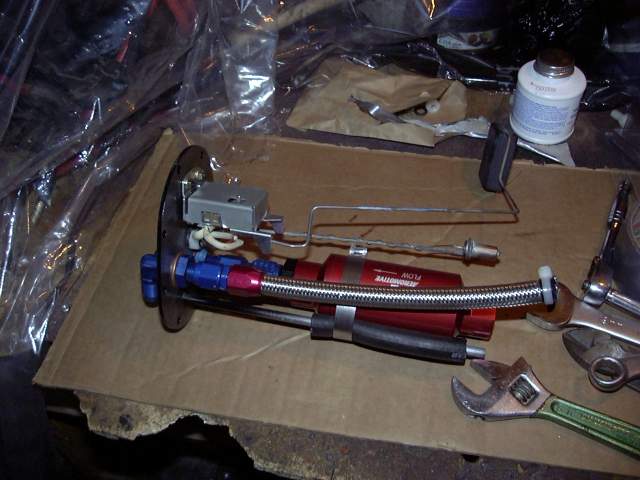
Since the old metering oil lines were cracked and leaking, I needed new ones. A trip to the local hydraulic store scored some nylon tubing. Here you can see the lines being mocked up. I ran into a slight problem on final assembly though; the 4MM nylon line didn't fit the stock banjo fittings! So I had to go back and order some 4.5MM tubing.
While waiting for the tubing I got a start on the other plumbing. First task was to install the radiator pipes. Short lengths of 1.5" silicone hose (this stuff is expensive!) was used as couplers to connect the pipe to the radiator and engine nipples. The clamps are cadmium plated T-bar style. Unlike regular hose clamps, the T-bar clamps exert equal force around the entire circumference of the hose, provide a much wider clamping area and don't mangle the hose like the regular clamps. They are only about $4 each so the investment is well worth it. By the time all the clamps were tightened, I could practically lift the front of the car with the rad pipes.
Since there was no hope of installing the large Aeromotive pump in place of the stocker, I chose to mount the pre-filter in it's place. The filter has a -10 ORB input, and a -10 ORB output. The input is left to suck fuel from the tank while a -10 ORB to -8 to flare adapter is installed on the output, and a female to female -8 adapter connects the filter to the bulkhead.
A short length of -6 braided stainless hose connects to the -6 bulkhead as a fuel return. The only worm gear style hose clamp on the entire car can be found here, holding the filter to the tank flange. A little bit of rubber fuel line hose keeps the filter from rubbing.
Since the old metering oil lines were cracked and leaking, I needed new ones. A trip to the local hydraulic store scored some nylon tubing. Here you can see the lines being mocked up. I ran into a slight problem on final assembly though; the 4MM nylon line didn't fit the stock banjo fittings! So I had to go back and order some 4.5MM tubing.
While waiting for the tubing I got a start on the other plumbing. First task was to install the radiator pipes. Short lengths of 1.5" silicone hose (this stuff is expensive!) was used as couplers to connect the pipe to the radiator and engine nipples. The clamps are cadmium plated T-bar style. Unlike regular hose clamps, the T-bar clamps exert equal force around the entire circumference of the hose, provide a much wider clamping area and don't mangle the hose like the regular clamps. They are only about $4 each so the investment is well worth it. By the time all the clamps were tightened, I could practically lift the front of the car with the rad pipes.
08-07-06, 10:59 AM
#4
Engine, Not Motor
Thread Starter
iTrader: (1)
Join Date: Feb 2001
Location: London, Ontario, Canada
Posts: 29,789
Likes: 0
Received 108 Likes
on
91 Posts
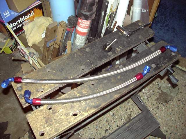
Next on the list was to make up some new oil cooler lines. The previous lines that I had a hydraulic shop make years ago were starting to show their age and the fittings were long past worn out with all kinds of kinks and dents in the tubing. These new lines are made of -10 braided stainless with the appropriate AN fittings. The construction of these lines is covered in the Archives, with a complete parts list.
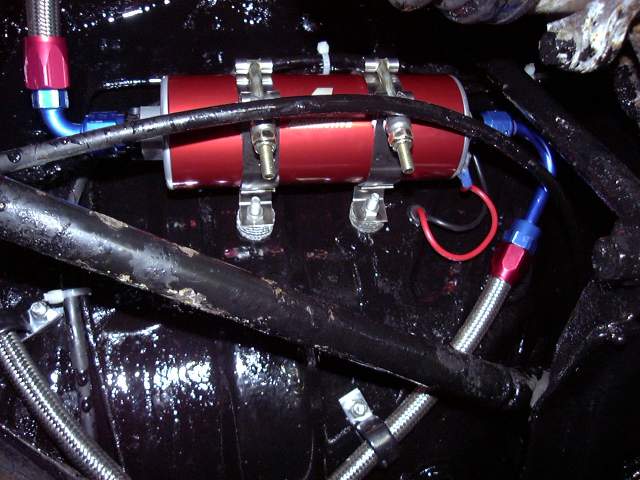
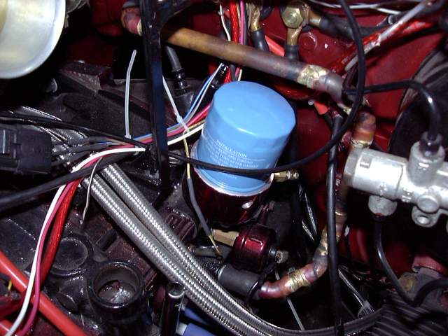
For a fuel filter, I chose the Mallory "competition" canister filter. It's a 10 micron filter with a replaceable element, all in a billet aluminum case. The filter has 2 inputs and two outputs, all 3/8" NPT. I only needed one input so the extra was plugged and then 3/8" NPT to -6 AN adapters installed. The single input goes to the fuel pump, and then each output goes to the appropriate fuel rail.
Once the filter was in place it was back into the engine bay to mount the Aeromotive regulator, attach the main power cables to the firewall passthroughs and install the oil cooler lines. The regulator comes with -6 ORB ports for the dual feed and single return, and a 1/8" NPT gauge port. Mounting it on the shock tower was a bit of a pain because the damper is in the way of the inside of the tower. Some creative bending of the fingers was necessary to hold the nuts in place while the bolts were tightened. Aeromotive really needs to revamp their mounting brackets because with the bracket installed on the regulator it is very irritating to get to the bolts, and you can't reach the bolts that secure the bracket to the regulator after the bracket is mounted to the car (got that? ).
).
The main power cables were actually a lot easier to install then I had thought since there was just enough space under the dash to fit a ratchet. A helper (my brother) kept the nuts in the engine bay from spinning. One ground goes to the starter, the other to the drivers frame rail. The positive cables go to the starter and to the main fuse box. See how easy grounding can be?

Finally my new metering oil tube arrived so I assembled the lines. A few zip ties keep them tidy. The metering nozzles were all cleaned with carb cleaner and tested as per the factory service manual prior to installation.
Back when I originally did the NA-turbo thing my original oil feed line was made of high pressure fuel injection hose. While it did work, I was always concerned with it blowing and it was a pain to keep it from leaking at the nipples. This new line is made from -6 braided stainless with AN fittings. I had first tried to make it out of -4 but soon gave up in frustration as -4 line is just much too small to work with (the braid kept unraveling no matter what I tried). Here's where it gets a bit weird. A Russel T3 style drain fitting was bolted to the turbo's inlet flange for an oil feed. This fitting fits the stock turbo oil inlet perfectly, seals with an o-ring and then provides a -10 flare. From there, a -10 AN to -6 AN flare reducer was used to connect to the 90 degree -6 end on the feed line. My oil cooler was originally modified with a 1/4" NPT fitting as a oil take off so a simple 90 degreee elbow and 1/4" NPT to -6AN adapter used to connect to the -6 straight end on the stainless line. Much of this is temporary because the upgraded turbo will require different fittings.
For a fuel filter, I chose the Mallory "competition" canister filter. It's a 10 micron filter with a replaceable element, all in a billet aluminum case. The filter has 2 inputs and two outputs, all 3/8" NPT. I only needed one input so the extra was plugged and then 3/8" NPT to -6 AN adapters installed. The single input goes to the fuel pump, and then each output goes to the appropriate fuel rail.
Once the filter was in place it was back into the engine bay to mount the Aeromotive regulator, attach the main power cables to the firewall passthroughs and install the oil cooler lines. The regulator comes with -6 ORB ports for the dual feed and single return, and a 1/8" NPT gauge port. Mounting it on the shock tower was a bit of a pain because the damper is in the way of the inside of the tower. Some creative bending of the fingers was necessary to hold the nuts in place while the bolts were tightened. Aeromotive really needs to revamp their mounting brackets because with the bracket installed on the regulator it is very irritating to get to the bolts, and you can't reach the bolts that secure the bracket to the regulator after the bracket is mounted to the car (got that?
).The main power cables were actually a lot easier to install then I had thought since there was just enough space under the dash to fit a ratchet. A helper (my brother) kept the nuts in the engine bay from spinning. One ground goes to the starter, the other to the drivers frame rail. The positive cables go to the starter and to the main fuse box. See how easy grounding can be?
Finally my new metering oil tube arrived so I assembled the lines. A few zip ties keep them tidy. The metering nozzles were all cleaned with carb cleaner and tested as per the factory service manual prior to installation.
Back when I originally did the NA-turbo thing my original oil feed line was made of high pressure fuel injection hose. While it did work, I was always concerned with it blowing and it was a pain to keep it from leaking at the nipples. This new line is made from -6 braided stainless with AN fittings. I had first tried to make it out of -4 but soon gave up in frustration as -4 line is just much too small to work with (the braid kept unraveling no matter what I tried). Here's where it gets a bit weird. A Russel T3 style drain fitting was bolted to the turbo's inlet flange for an oil feed. This fitting fits the stock turbo oil inlet perfectly, seals with an o-ring and then provides a -10 flare. From there, a -10 AN to -6 AN flare reducer was used to connect to the 90 degree -6 end on the feed line. My oil cooler was originally modified with a 1/4" NPT fitting as a oil take off so a simple 90 degreee elbow and 1/4" NPT to -6AN adapter used to connect to the -6 straight end on the stainless line. Much of this is temporary because the upgraded turbo will require different fittings.
08-07-06, 10:59 AM
#5
Engine, Not Motor
Thread Starter
iTrader: (1)
Join Date: Feb 2001
Location: London, Ontario, Canada
Posts: 29,789
Likes: 0
Received 108 Likes
on
91 Posts
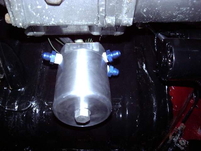
The fuel pump was mounted on the underside of the drivers storage bin/rear seat cavity. These pumps tend to be a little loud so I inserted toilet tank washers between the clamps and car to try and keep it quiet. It's still a huge pump so it will definitely make noise. If it gets bad, I'll just wrap the pump in Dynamat. The pump offers a -8 ORB inlet and -6 ORB outlet. Adapters were used to turn those into AN flare fittings.
After the pump was mounted, the fuel flange was installed on the tank. To my surprise it actually fit. A new gasket and orange silicone goo seal flange to the tank. I'm a bit worried about this whole arrangement since it means the pump must draw the fuel out of the tank. Conventional wisdom says that these pumps should have a gravity feed inlet with the pickup mounted as low in the tank as possible. So I may experience suction problems when the fuel level in the tank is low. If that's the case, I'll pick up a brand new tank from Mazda and add a sump with some external bungs. No way in hell I'm going to attempt to weld on a tank that has held fuel.
And then the lines get installed. The thick -8 line is feed to the pump while the thin -6 line is return from the regulator.
Here are the lines connected to the pump. Space is tight but luckily AN fittings come in all kinds of weird sizes, including 120 degree swivel...
Also notice the ever important rubber grommet where the power wires pass through the sheet metal, and the dielectric grease on the connections.
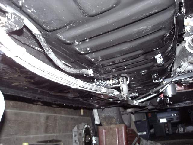
The fuel lines just fit between the differential mount and the frame rail.
After the pump was mounted, the fuel flange was installed on the tank. To my surprise it actually fit. A new gasket and orange silicone goo seal flange to the tank. I'm a bit worried about this whole arrangement since it means the pump must draw the fuel out of the tank. Conventional wisdom says that these pumps should have a gravity feed inlet with the pickup mounted as low in the tank as possible. So I may experience suction problems when the fuel level in the tank is low. If that's the case, I'll pick up a brand new tank from Mazda and add a sump with some external bungs. No way in hell I'm going to attempt to weld on a tank that has held fuel.
And then the lines get installed. The thick -8 line is feed to the pump while the thin -6 line is return from the regulator.
Here are the lines connected to the pump. Space is tight but luckily AN fittings come in all kinds of weird sizes, including 120 degree swivel...
Also notice the ever important rubber grommet where the power wires pass through the sheet metal, and the dielectric grease on the connections.
The fuel lines just fit between the differential mount and the frame rail.
08-07-06, 11:00 AM
#6
Engine, Not Motor
Thread Starter
iTrader: (1)
Join Date: Feb 2001
Location: London, Ontario, Canada
Posts: 29,789
Likes: 0
Received 108 Likes
on
91 Posts
Rubber insulated hose clamps secure the lines along the bottom of the car and zip ties keep them from rubbing. Braided stainless will abrade through anything, even POR-15, so it's important to keep them from wiggling around.
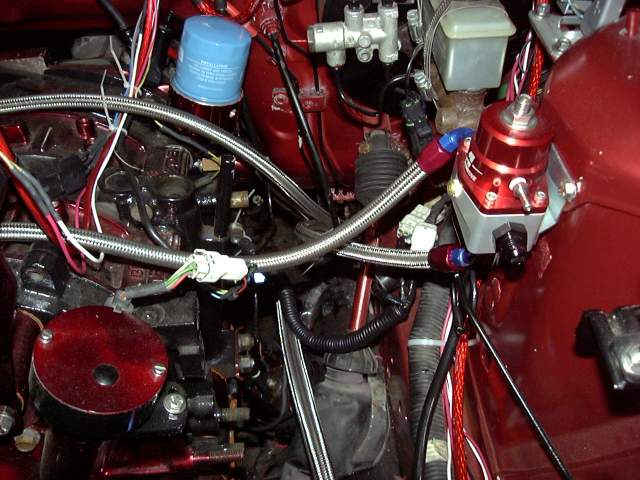
Now that the fuel lines were run to the front of the car, the connections could be made to the fuel rail. The NA fuel rail has a M12 x 1.25 thread on each end. Note that this is different then the turbo rails as they have an M14 x 1.5 thread on one end. Two Earls Delorto carb adapters were used. I was pleasantly surprised to find that these adapters come with Dowty seals to prevent leaks. I went a step further and also used Teflon sealing compound on the threads.
One side of the rail goes to the feed from the filter (left in the picture) while the right side of the rail heads up to the pressure regulator. Note the return line at the bottom of the regulator that goes all the way to the back of the car.

A closeup of the lines around the pressure regulator.
At this point my 1680CC injectors arrived at the local Ford dealer and I couldn't resist installing them. The ATP Turbo injector holders have a 1/4" NPT port at the top so I used -6 AN tees with 1/4" NPT threads on the bottom to make the fuel connections. The electrical plug was turned towards the intake to help keep it out of exhaust heat. If I had been thinking when I designed the intake, I would have mounted the injectors on the inside of it facing the engine instead of on the outside facing the exhaust. Oh well...
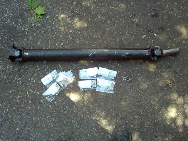
This is the reason I tell people to go to the local driveline shop. I had my driveshaft rebuilt with brand new u-joints, had the front yolk polished and the rear yolk replaced. The u-joints are replaceable and have grease fittings so they won't wear out in the future. The cost? Nothing.
I also stopped by the Mazda dealer and picked up new driveshaft hardware since mine was pretty rusted and worn.
Now that the fuel lines were run to the front of the car, the connections could be made to the fuel rail. The NA fuel rail has a M12 x 1.25 thread on each end. Note that this is different then the turbo rails as they have an M14 x 1.5 thread on one end. Two Earls Delorto carb adapters were used. I was pleasantly surprised to find that these adapters come with Dowty seals to prevent leaks. I went a step further and also used Teflon sealing compound on the threads.
One side of the rail goes to the feed from the filter (left in the picture) while the right side of the rail heads up to the pressure regulator. Note the return line at the bottom of the regulator that goes all the way to the back of the car.
A closeup of the lines around the pressure regulator.
At this point my 1680CC injectors arrived at the local Ford dealer and I couldn't resist installing them. The ATP Turbo injector holders have a 1/4" NPT port at the top so I used -6 AN tees with 1/4" NPT threads on the bottom to make the fuel connections. The electrical plug was turned towards the intake to help keep it out of exhaust heat. If I had been thinking when I designed the intake, I would have mounted the injectors on the inside of it facing the engine instead of on the outside facing the exhaust. Oh well...
This is the reason I tell people to go to the local driveline shop. I had my driveshaft rebuilt with brand new u-joints, had the front yolk polished and the rear yolk replaced. The u-joints are replaceable and have grease fittings so they won't wear out in the future. The cost? Nothing.
I also stopped by the Mazda dealer and picked up new driveshaft hardware since mine was pretty rusted and worn.
08-07-06, 11:00 AM
#7
Engine, Not Motor
Thread Starter
iTrader: (1)
Join Date: Feb 2001
Location: London, Ontario, Canada
Posts: 29,789
Likes: 0
Received 108 Likes
on
91 Posts
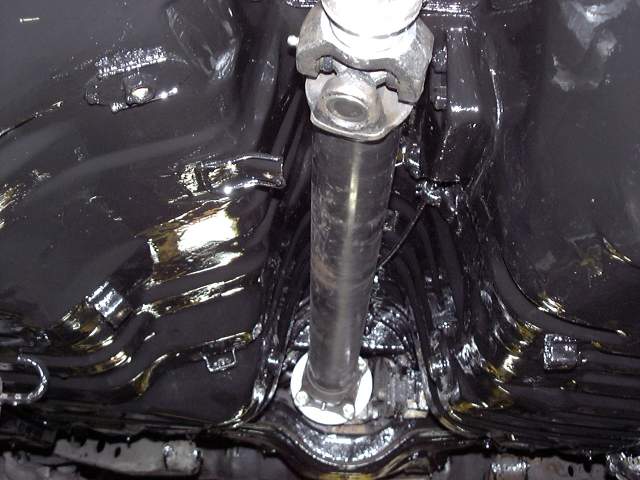
The driveshaft installed without incident. Anti-seize was applied to the differential flange to prevent rust, while the front yolk was coated in Vascelene to prevent damage to the seal upon insertion.
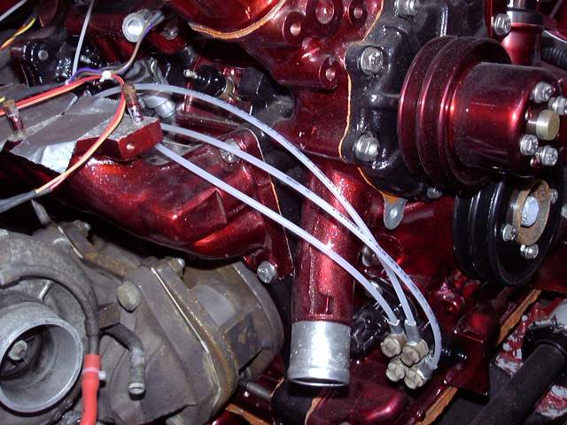
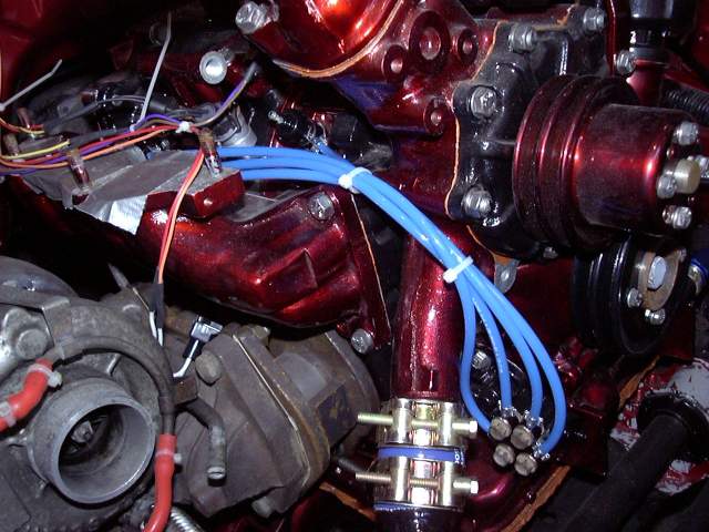
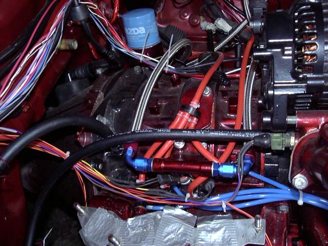
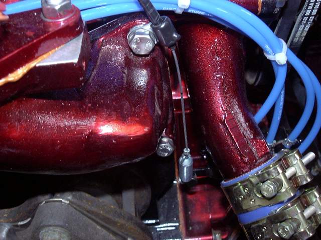
My old metering oil "vacuum" spider was looking pretty sketchy, so I replaced all the old rubber with new silicone hose. This "vacuum" spider is actually an air supply to the nozzles. It connects to a fresh air source before the throttle bodies which insures that engine vacuum always draws oil through the injectors.
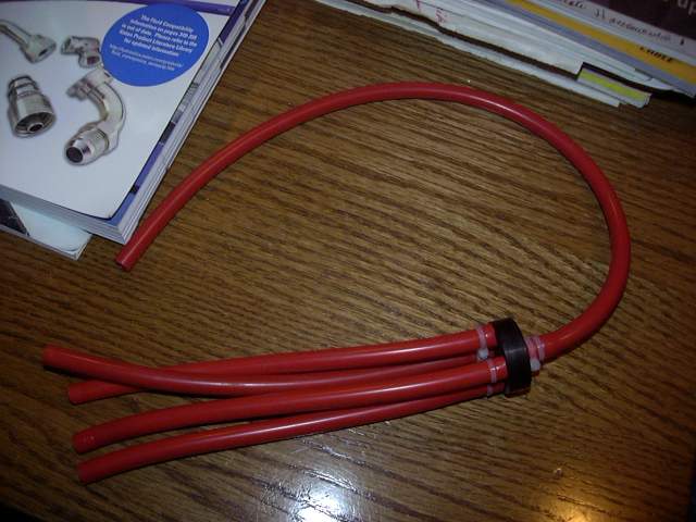
Here is the air spider installed as well as the air line to the primary injector air bleed. Don't leave the injector bleed line out because the air jet shooting at the injector really helps atomize fuel and drastically improves idle quality.
I wish Mazda had more evenly spaced the oil injectors so my hoses would be even on each side of the fuel rail.
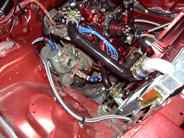
The black coolant hoses from the rear iron and water pump housing are water supply to the turbo. I used fuel injection hose because it easily handles the pressure, is easy to bend and I'm not sure if the upgraded turbo I end up with will need a water supply so I didn't want to waste time and money on braided stainless and AN.
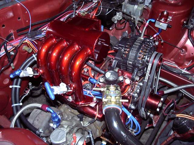
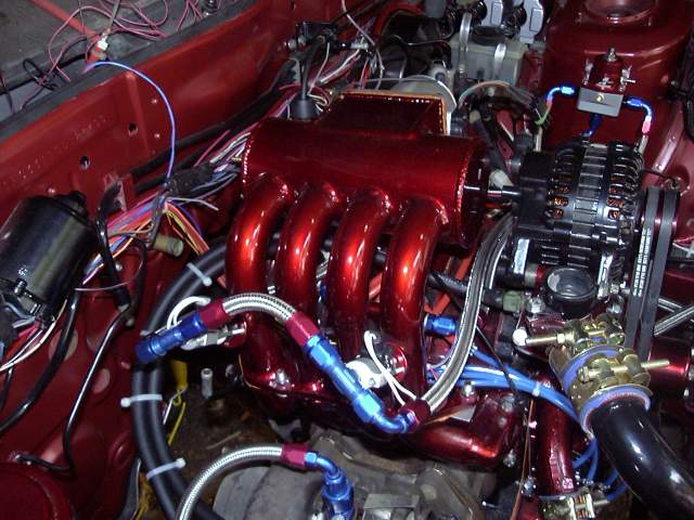
The moment of truth! At this point all the work on the top of the engine was done so it was time to install the upper intake manifold. I had to run a die down the stock lower intake manifold studs to increase the amount of thread available but besides that it fit perfectly. I was very, very relieved to find that the hood still closed. I also snuck the dual belts on before I installed the intake.
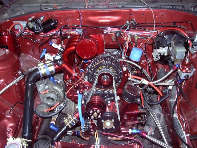
Another view of the intake manifold.
My old metering oil "vacuum" spider was looking pretty sketchy, so I replaced all the old rubber with new silicone hose. This "vacuum" spider is actually an air supply to the nozzles. It connects to a fresh air source before the throttle bodies which insures that engine vacuum always draws oil through the injectors.
Here is the air spider installed as well as the air line to the primary injector air bleed. Don't leave the injector bleed line out because the air jet shooting at the injector really helps atomize fuel and drastically improves idle quality.
I wish Mazda had more evenly spaced the oil injectors so my hoses would be even on each side of the fuel rail.
The black coolant hoses from the rear iron and water pump housing are water supply to the turbo. I used fuel injection hose because it easily handles the pressure, is easy to bend and I'm not sure if the upgraded turbo I end up with will need a water supply so I didn't want to waste time and money on braided stainless and AN.
The moment of truth! At this point all the work on the top of the engine was done so it was time to install the upper intake manifold. I had to run a die down the stock lower intake manifold studs to increase the amount of thread available but besides that it fit perfectly. I was very, very relieved to find that the hood still closed. I also snuck the dual belts on before I installed the intake.
Another view of the intake manifold.
Trending Topics
08-07-06, 11:01 AM
#8
Engine, Not Motor
Thread Starter
iTrader: (1)
Join Date: Feb 2001
Location: London, Ontario, Canada
Posts: 29,789
Likes: 0
Received 108 Likes
on
91 Posts
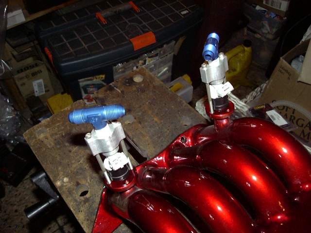
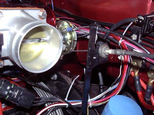
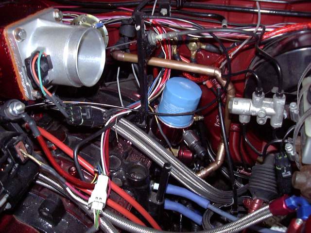
With the manifold in place, I could make the fuel lines. On the left, the feed line goes to the fuel filter under the car. The right line leads back to the pressure regulator. The little middle line was a bit of a pain because I could not come up with anything better. The only other option was to make a metal line but it would be very difficult to install due to it's ridgitity. This line was relatively easy to install but it is also the highest point in the fuel system and in a warm area. I'm really hoping that vapor lock won't be an issue. It shouldn't, since the lines are under pressure (which raises the boiling point). If I have issues, I'll mount a fuel cooler along the frame rail.
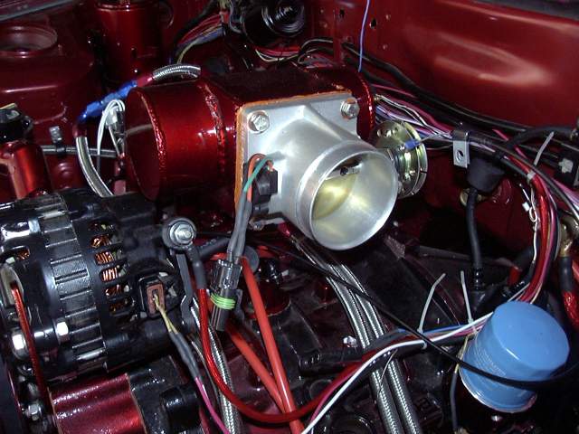
The Edlebrock throttle body installed easily with the supplied gasket and a bit of gasket goo to assure a good seal. You can see that there is a actuator cable attached to the spool. This is NOT the throttle cable, but the cable to actuate the metering oil pump. More on that later.
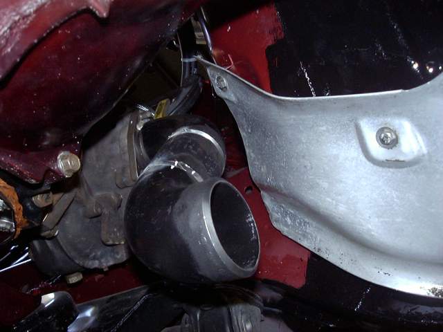
Time to make a downpipe. I started with a turbo flange from Mazdatrix and some SCH 40 weld els from the local industrial plumbing supplier. These els are very cheap, nice and thick and easy to work with. I prefer a thicker downpipe because it doesn't have a "pingy" noise and helps keep the heat in the pipe and out of the engine bay. It's a little heavier then most of the aftermarket downpipes but in my mind I would rather have a few more pounds then deal with the noise. And it will last forever, even though this one is just temporary as I'll have to make a new one when I switch turbos.
The first step was to tack a 90 degree el onto the flange. I'm using 2.5" here.
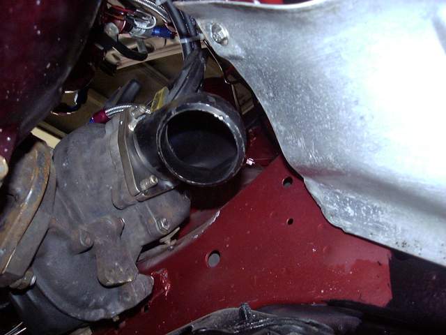
Then a 4" section of pipe to extend the pipe downwards. Notice the bevel on the joints. This assures good weld penetration and also eliminates grinding.
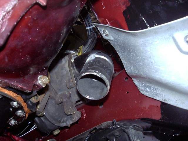
Another 90 degree el was tacked into place.
The Edlebrock throttle body installed easily with the supplied gasket and a bit of gasket goo to assure a good seal. You can see that there is a actuator cable attached to the spool. This is NOT the throttle cable, but the cable to actuate the metering oil pump. More on that later.
Time to make a downpipe. I started with a turbo flange from Mazdatrix and some SCH 40 weld els from the local industrial plumbing supplier. These els are very cheap, nice and thick and easy to work with. I prefer a thicker downpipe because it doesn't have a "pingy" noise and helps keep the heat in the pipe and out of the engine bay. It's a little heavier then most of the aftermarket downpipes but in my mind I would rather have a few more pounds then deal with the noise. And it will last forever, even though this one is just temporary as I'll have to make a new one when I switch turbos.
The first step was to tack a 90 degree el onto the flange. I'm using 2.5" here.
Then a 4" section of pipe to extend the pipe downwards. Notice the bevel on the joints. This assures good weld penetration and also eliminates grinding.
Another 90 degree el was tacked into place.
08-07-06, 11:01 AM
#9
Engine, Not Motor
Thread Starter
iTrader: (1)
Join Date: Feb 2001
Location: London, Ontario, Canada
Posts: 29,789
Likes: 0
Received 108 Likes
on
91 Posts
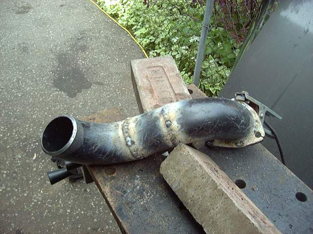
And then the whole mess was finish welded on the bench. Not too shabby welding job, eh? 
That pipe took about half an hour to cool to the point where I could pick it up, so in the mean time I installed the throttle cable bracket. The bracket was made using the stock throttle cable bracket from the original throttle body, a small square of 12 gauge sheet metal and then a piece of angle iron. The sheet metal base bolts to the two holes in the top of the rotor housing that used to hold the vacuum spider and the angle iron is mounted vertically to it. The OEM throttle bracket was then welded to the angle iron.
The top cable is the aforementioned metering oil cable. It's a simple arrangement of bicycle brake cable held in place with a small cable clamp. A bolt extends through an extra hole in the throttle spool and the cable attaches to that with a standard crimp-on eyelet. A nylock nut prevents the eyelet from slipping off.
On the metering oil pump end, another cable clamp secures the cable to the lower intake mounting bolt. A spring connects to the metering oil pump lever and another eyelet connects the cable to the spring. The spring is necessary as the metering oil pump is adjusted fairly loose, about twice that of stock. So it reaches wide open before the throttle plate does. The spring takes up the slack. OK, so it's a little Rube Goldburg, but no more then the stock setup with rods and shims.
Now that the downpipe had cooled, the rest of it could be made. Because it's all temporary, I just used cheap aluminized steel 2.5" exhaust tubing. It was assembled to the proper length, and then welded to the downpipe.
The finished downpipe also has an oxygen sensor bung just visible on the bottom of the pipe after the turbo flange.
All told there is about 2 hours invested in this pipe from start to completion, and under $100.
08-07-06, 11:01 AM
#10
Engine, Not Motor
Thread Starter
iTrader: (1)
Join Date: Feb 2001
Location: London, Ontario, Canada
Posts: 29,789
Likes: 0
Received 108 Likes
on
91 Posts
Here's a poor view of the turbo water lines, the downpipe and the O2 sensor location. I'm just using an old narrowband sensor for mockup and the initial start. In general I tend to start with a narrowband and then move to a wideband when the car is no longe running pig rich. It prevents fouling out the much more expensive wideband during the initial rough tune.
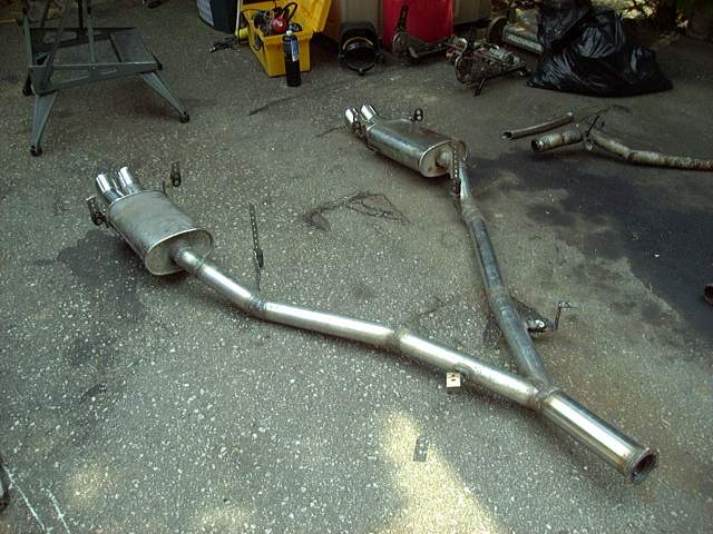
Now that the downpipe was done I could continue on with the exhaust. My old and abused 2.5" catback had taken so much over the years that when I did the original turbo-NA project I actually had to replace it with a spare stock catback and weld on my stainless mufflers. Needless to say that awful thing had to go. The new catback is also 2.5" but made of 304 thick walled stainless.
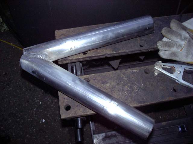
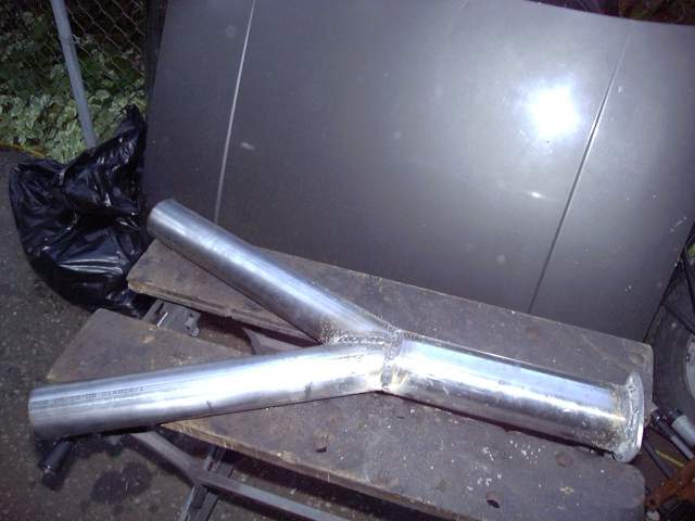
First, the Y pipe had to be created. The temporary downpipe was made with a 3" 3 bolt header style flange, so I welded the same style flange to a foot long section of 3" stainless tubing. The flange is temporary as when I make the "real" downpipe (after the turbo is upgraded) I will be using a v-band setup. Two pieces of 2.5" tubing were cut and then given a 45 degree bevel on one end. Those bevels fit together to form a merge point. The resulting "V" pipe was then positioned at the outlet of the 3" tubing to get the angles right.
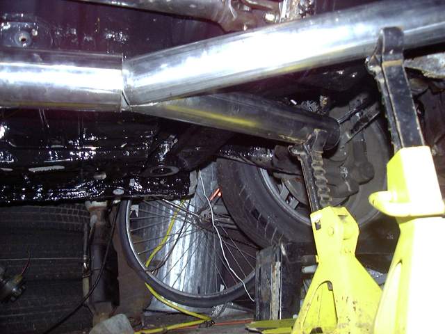
Here's the V pipe welded together. There is still some cutting needed at the base of the V so that the OD of the V lines up with the OD of the 3" tube.
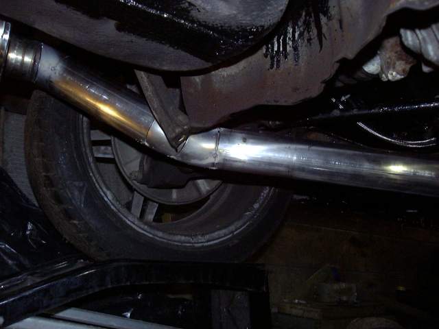
The V was again positioned under the car, tacked into place, and the whole assembly removed from the car to be welded on the bench. Once it was welded, I went into the 3" section of pipe with a die grinder and finished off the inside of the Y. It took some grinding to remove the excess material from the pipe joint and make a smooth and full-flowing transition.
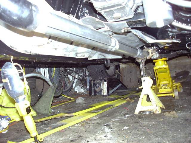
After bolting the Y pipe back onto the downpipe and positioning it evenly, the rest of the system was started. To make things easier I tried to keep the position of the bends close to the stock catback so there would not be a lot of guesswork as far as angles and positioning goes. To start the tailpipe another section of tubing was welded to the Y pipe at a slight angle. The system was then continued by using sections of stainless 90 degree weld els that had been trimmed to form various angles.
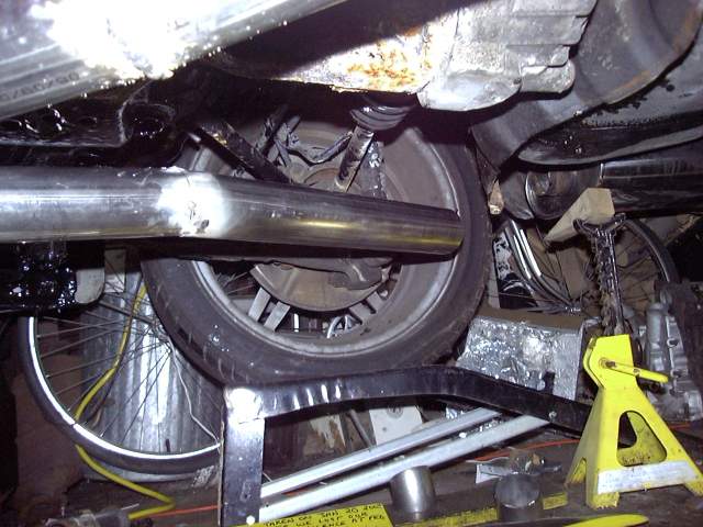
This was work that took far longer then it should have due to lack of space. Each pipe took several trips in and out of the garage which mean actually crawling under the car since there is not enough clearance side to side to squeeze by. The drivers side had to be tack welded, removed from the car, finish welded then reinstalled so the passenger side could be tacked. Finally when the whole system was done it would not fit under the car to allow it to be slid out the front of the garage since it was slightly wider then the wheelbase! So I had to jack each end of the car up, slide it under the wheels, let the car back down on the ramps, and continue...Sometimes I wonder how I get anything accomplished...
Now that the downpipe was done I could continue on with the exhaust. My old and abused 2.5" catback had taken so much over the years that when I did the original turbo-NA project I actually had to replace it with a spare stock catback and weld on my stainless mufflers. Needless to say that awful thing had to go. The new catback is also 2.5" but made of 304 thick walled stainless.
First, the Y pipe had to be created. The temporary downpipe was made with a 3" 3 bolt header style flange, so I welded the same style flange to a foot long section of 3" stainless tubing. The flange is temporary as when I make the "real" downpipe (after the turbo is upgraded) I will be using a v-band setup. Two pieces of 2.5" tubing were cut and then given a 45 degree bevel on one end. Those bevels fit together to form a merge point. The resulting "V" pipe was then positioned at the outlet of the 3" tubing to get the angles right.
Here's the V pipe welded together. There is still some cutting needed at the base of the V so that the OD of the V lines up with the OD of the 3" tube.
The V was again positioned under the car, tacked into place, and the whole assembly removed from the car to be welded on the bench. Once it was welded, I went into the 3" section of pipe with a die grinder and finished off the inside of the Y. It took some grinding to remove the excess material from the pipe joint and make a smooth and full-flowing transition.
After bolting the Y pipe back onto the downpipe and positioning it evenly, the rest of the system was started. To make things easier I tried to keep the position of the bends close to the stock catback so there would not be a lot of guesswork as far as angles and positioning goes. To start the tailpipe another section of tubing was welded to the Y pipe at a slight angle. The system was then continued by using sections of stainless 90 degree weld els that had been trimmed to form various angles.
This was work that took far longer then it should have due to lack of space. Each pipe took several trips in and out of the garage which mean actually crawling under the car since there is not enough clearance side to side to squeeze by. The drivers side had to be tack welded, removed from the car, finish welded then reinstalled so the passenger side could be tacked. Finally when the whole system was done it would not fit under the car to allow it to be slid out the front of the garage since it was slightly wider then the wheelbase! So I had to jack each end of the car up, slide it under the wheels, let the car back down on the ramps, and continue...Sometimes I wonder how I get anything accomplished...
08-07-06, 11:02 AM
#11
Engine, Not Motor
Thread Starter
iTrader: (1)
Join Date: Feb 2001
Location: London, Ontario, Canada
Posts: 29,789
Likes: 0
Received 108 Likes
on
91 Posts
The passenger side was next. Here's the section of pipe right after the Y. For slight angles it's not really worth using the els, so I just cut the pipe at a slight angle and welded it where I wanted it.
Bends at a more extreme angle would be heavily restricted if the pipe was just cut and welded (unless many cuts and many welds are made) so the weld els are useful here. I generally just get 90 degree els and then cut them apart into basically random angles. A box of those is very handy for stuff like this.

When all the tack welds were done, the system was removed from the car and then brought over to the bench to be finish welded. Here's the finished exhaust before the welds were cleaned up. I know someone is going to make fun of my mufflers but I love these things. I've had them on the car since the late '90s, long before every rice Honda had copies. They are full stainless, sound great, look great (in my opinion) and are unique on the RX-7.
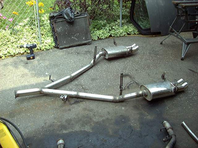
Another view of the catback. The hangers were purchased at a local parts store and are very well designed. Basically they are a section of thick rubber riveted between two steel hangers. Easy to work with and they don't rattle around like the stock rubber doughnuts. One thing that annoys the hell out of me is a car where the exhaust moves side to side as it goes down the road. These hangers keep the exhaust still but can bend when necessary (ie. when the engine torques).
Just after this picture was taken the whole exhaust was gone over with a grinder and flap wheel to remove all welding splatter and provide a rough surface for the paint to grip...
It's not often that I do something that fails utterly and completely. I'm not saying that I'm perfect or better then anyone else but I do put a lot of thought into everything I do so things tend to work out. This is not one of those times. I really thought this would work since the concept is sound but my execution was not for reasons explained below.
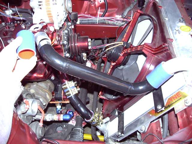
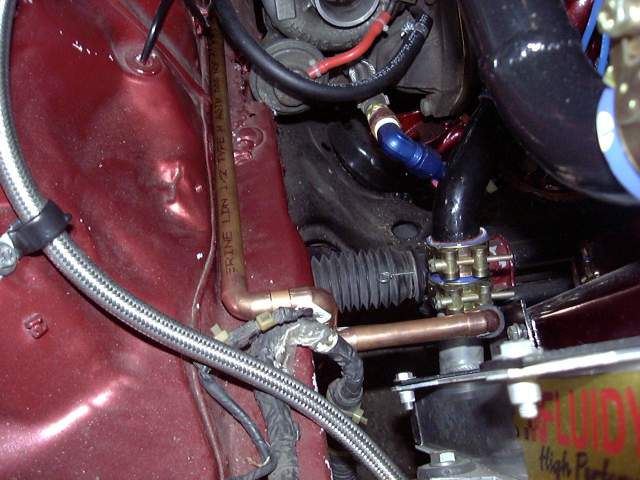
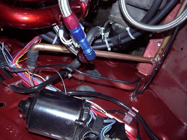
Since I made solid radiator pipes I figured I would do the same thing with the heater lines. After all, the drivers heater line is notorious for failure and the passenger line is totally in the way of the turbo. The plan was to use standard copper piping to replace the rubber hoses, so I went about mocking up the lines. Here's the passenger side line where it connects to the radiator.
Seems to fit very well.
Bends at a more extreme angle would be heavily restricted if the pipe was just cut and welded (unless many cuts and many welds are made) so the weld els are useful here. I generally just get 90 degree els and then cut them apart into basically random angles. A box of those is very handy for stuff like this.
When all the tack welds were done, the system was removed from the car and then brought over to the bench to be finish welded. Here's the finished exhaust before the welds were cleaned up. I know someone is going to make fun of my mufflers but I love these things. I've had them on the car since the late '90s, long before every rice Honda had copies. They are full stainless, sound great, look great (in my opinion) and are unique on the RX-7.
Another view of the catback. The hangers were purchased at a local parts store and are very well designed. Basically they are a section of thick rubber riveted between two steel hangers. Easy to work with and they don't rattle around like the stock rubber doughnuts. One thing that annoys the hell out of me is a car where the exhaust moves side to side as it goes down the road. These hangers keep the exhaust still but can bend when necessary (ie. when the engine torques).
Just after this picture was taken the whole exhaust was gone over with a grinder and flap wheel to remove all welding splatter and provide a rough surface for the paint to grip...
It's not often that I do something that fails utterly and completely. I'm not saying that I'm perfect or better then anyone else but I do put a lot of thought into everything I do so things tend to work out. This is not one of those times. I really thought this would work since the concept is sound but my execution was not for reasons explained below.
Since I made solid radiator pipes I figured I would do the same thing with the heater lines. After all, the drivers heater line is notorious for failure and the passenger line is totally in the way of the turbo. The plan was to use standard copper piping to replace the rubber hoses, so I went about mocking up the lines. Here's the passenger side line where it connects to the radiator.
Seems to fit very well.
08-07-06, 11:02 AM
#12
Engine, Not Motor
Thread Starter
iTrader: (1)
Join Date: Feb 2001
Location: London, Ontario, Canada
Posts: 29,789
Likes: 0
Received 108 Likes
on
91 Posts
That line ends up at the firewall just above the exhaust area. In stock configuration the rubber lines get baked by exhaust heat.
Have you figured out the problem yet?
To assemble the pipes I chose to braze them. Soldering is easy and would work but the temperature at which solder mounts seemed to be a little low for an engine bay. A few pre-fluxed bronze brazing rods and a MAPP gas/oxygen torch was used after all the joints were thoroughly cleaned.
The problem with these pipes is easy to see here.
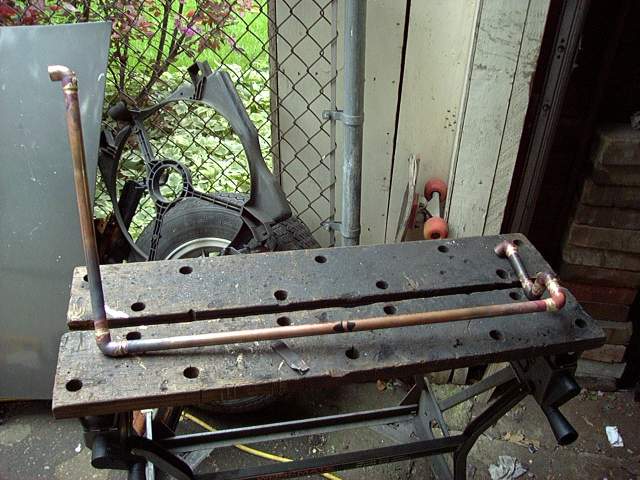
The drivers side was done in the same way but required some stranger bends. To hold things in place I was using bits of heater hose slipped over the nipples and the pipe. The plan was to ultimately use silicone couplers and T-bolt clamps, but that didn't quite work...
Once the pipe was brazed and put back into place, the problem became obvious when I tried to tighten the clamps. In using the plumbing joints as the clamping surface, I had not left enough area for the hose and clamp to get a real grip. Only about 1/2" is not enough to make a solid connection especially with slippery silicone hose. Every time I tried to tighten the clamp, the pipe just squeezed out. Even if I had managed to clamp it in the driveway, it's highly likely that it would vibrate loose after a few minutes of operation.
So if you are going to do this, leave at least 2" of clamping surface just like the stock nipples provide.
These pipes were removed, thrown into the spare parts bin and then 5/8" silicone heater line was used in place.
To finish off the exhaust I used POR-20 "aluminum" paint. Its a high temp coating from the POR-15 people that is supposed to be good to 1400F. It's strange stuff in that after it dries, it's not really dry. You can still take it off easily with your finger nail. Only after half an hour or so at 400F does it harden. Primarily I wanted the pipes to be one colour and to keep rust off the welds. This is the same paint I will be using when I make the new turbo manifold.

That's it for this update. A lot has taken place since I started writing this post so in the meantime the exhaust has been bolted to the car, a bunch of wiring work done, gauges installed and the intercooler is currently being mounted. Very soon I should be starting the car so the excitement builds...The plan is to break in the engine during the remaining summer months, then deal with upgrading the turbo over the winter as well as finishing the interior. Probably a quick trip to the body shop to sort out a few issues, suspension in the spring and then it's done!
Have you figured out the problem yet?
To assemble the pipes I chose to braze them. Soldering is easy and would work but the temperature at which solder mounts seemed to be a little low for an engine bay. A few pre-fluxed bronze brazing rods and a MAPP gas/oxygen torch was used after all the joints were thoroughly cleaned.
The problem with these pipes is easy to see here.
The drivers side was done in the same way but required some stranger bends. To hold things in place I was using bits of heater hose slipped over the nipples and the pipe. The plan was to ultimately use silicone couplers and T-bolt clamps, but that didn't quite work...
Once the pipe was brazed and put back into place, the problem became obvious when I tried to tighten the clamps. In using the plumbing joints as the clamping surface, I had not left enough area for the hose and clamp to get a real grip. Only about 1/2" is not enough to make a solid connection especially with slippery silicone hose. Every time I tried to tighten the clamp, the pipe just squeezed out. Even if I had managed to clamp it in the driveway, it's highly likely that it would vibrate loose after a few minutes of operation.
So if you are going to do this, leave at least 2" of clamping surface just like the stock nipples provide.
These pipes were removed, thrown into the spare parts bin and then 5/8" silicone heater line was used in place.
To finish off the exhaust I used POR-20 "aluminum" paint. Its a high temp coating from the POR-15 people that is supposed to be good to 1400F. It's strange stuff in that after it dries, it's not really dry. You can still take it off easily with your finger nail. Only after half an hour or so at 400F does it harden. Primarily I wanted the pipes to be one colour and to keep rust off the welds. This is the same paint I will be using when I make the new turbo manifold.
That's it for this update. A lot has taken place since I started writing this post so in the meantime the exhaust has been bolted to the car, a bunch of wiring work done, gauges installed and the intercooler is currently being mounted. Very soon I should be starting the car so the excitement builds...The plan is to break in the engine during the remaining summer months, then deal with upgrading the turbo over the winter as well as finishing the interior. Probably a quick trip to the body shop to sort out a few issues, suspension in the spring and then it's done!
 08-07-06, 11:13 AM
#14
Rotartist
iTrader: (13)
Join Date: Sep 2003
Location: Spring Hill TN 37174
Posts: 7,252
Likes: 0
Received 2 Likes
on
2 Posts
Wow, That is great. What info led you to the design of the upper manifold? I have seen a very similar setup on the RACING BEAT 4 rotor.... As far as the manifold configuration goes.
08-07-06, 12:02 PM
#16
I'm with stupid -----^
Join Date: Mar 2001
Location: Calgary, AB, Canada
Posts: 994
Likes: 0
Received 0 Likes
on
0 Posts
Wow.. it's incredible that you could spend that many years to create something that ghetto.. but hey. if you wanna feel proud about having household plumbing everytime you lift your hood...
 08-07-06, 12:12 PM
#18
Senior Member

Join Date: Sep 2005
Location: Performance Improvements
Posts: 448
Likes: 0
Received 0 Likes
on
0 Posts
im wqondering aaron .. with all thoes rigid lines and whatnot im asuming ur using rigid engine and tranny mounts so as to stop everything from breaking wheen u get on that beast i only ask because even with brnd new stock mounts an engine will shake around like a small dog humping a football and it would be awful to see all that hard work get demolished .. but either way you are a pioneer to us all congrats on all the progress and you have answered alot of questions some of the newcomers have had
08-07-06, 12:21 PM
#19
Engine, Not Motor
Thread Starter
iTrader: (1)
Join Date: Feb 2001
Location: London, Ontario, Canada
Posts: 29,789
Likes: 0
Received 108 Likes
on
91 Posts
Originally Posted by RRTEC
Wow, That is great. What info led you to the design of the upper manifold? I have seen a very similar setup on the RACING BEAT 4 rotor.... As far as the manifold configuration goes.
Originally Posted by Chris Ng
Wow.. it's incredible that you could spend that many years to create something that ghetto.. but hey. if you wanna feel proud about having household plumbing everytime you lift your hood...
And what plumbing pipe? Not that there is anything wrong with plumbing pipe, but there isn't any in my engine bay...
Originally Posted by rotary downshift
im wqondering aaron .. with all thoes rigid lines and whatnot im asuming ur using rigid engine and tranny mounts so as to stop everything from breaking wheen u get on that beast i only ask because even with brnd new stock mounts an engine will shake around like a small dog humping a football and it would be awful to see all that hard work get demolished .. but either way you are a pioneer to us all congrats on all the progress and you have answered alot of questions some of the newcomers have had
08-07-06, 01:05 PM
#22
Originally Posted by Chris Ng
Wow.. it's incredible that you could spend that many years to create something that ghetto.. but hey. if you wanna feel proud about having household plumbing everytime you lift your hood...
I hope I get to see this car in person someday. Nice work.
08-07-06, 01:16 PM
#24
LSX7
iTrader: (4)
Join Date: Mar 2001
Location: Florida
Posts: 688
Likes: 0
Received 0 Likes
on
0 Posts
If Im being honest, ghetto is the first word that came to mind. Even if you dont have a big budget to work with I think you could have done a much cleaner job for less money.
Ill give you an 'A' for effort and creativity but in the looks department.... Aaron, you painted your entire engine including your intake candy apple red??? You have AN fittings all over the place and a mess of wiring throughout the engine bay. Why not buy a used exhaust system to save yourself some time which might translate into some money savings? I really hope you dont plan on using those straps to hold the exhaust to the car. Do you really need that big aeromotive fuel pump? Why not use the RP (nippondenso) fuel pump which is probably cheaper and wont require any fabrication. Do you plan on outflowing the RP pump?
In any case, no one can deny you did a buttload of work.
Cheers
Chris
08-07-06, 01:23 PM
#25
Originally Posted by Rotorlution
Ill give you an 'A' for effort and creativity but in the looks department.... Aaron, you painted your entire engine including your intake candy apple red???
Now back to reality...
Maybe he wanted to do things original. *gasp* What a concept!!! Considering he's doing a 6port turbo, I figured you might, just might, of caught onto that fact. Guess not...