
Finally! Pictures and Status Of My Turbo-NA-Bridgeport

Thread Starter
Joined: Feb 2001
Posts: 29,798
Likes: 128
From: London, Ontario, Canada
Finally! Pictures and Status Of My Turbo-NA-Bridgeport
It has been nearly two years since I last posted the status of project Tina (phase 2). The thread can be found as my winter project, posted in early 2003. It contains the first part of the story. But to summarize, in Dec. 2002 I decided I would pull Tina's engine for a port and rebuild. After that, the project ballooned to include a quick engine bay painting, interior replacement, Microtech LT-8, bridgeport, big turbo, new exhaust, transmission rebuild, etc.
I honestly can't say that I put massive amounts of time into the project until early last summer. I had a busy time in my life, with multiple side projects, big meets (can you say Revolution?), and of course my day job. Because of this, work has been slow, with spurts of activity separated by periods of idle time. But anyway, in the past few months I have been working steadily and have some significant progress. So let's get to the pictures already...
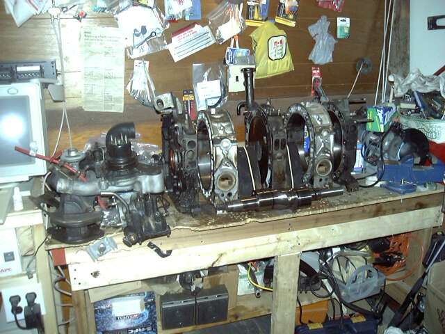
When we last left off, the engine was disassembled on the bench. Basically, it sat like that until the fall of 2003, but I'm getting ahead of myself...
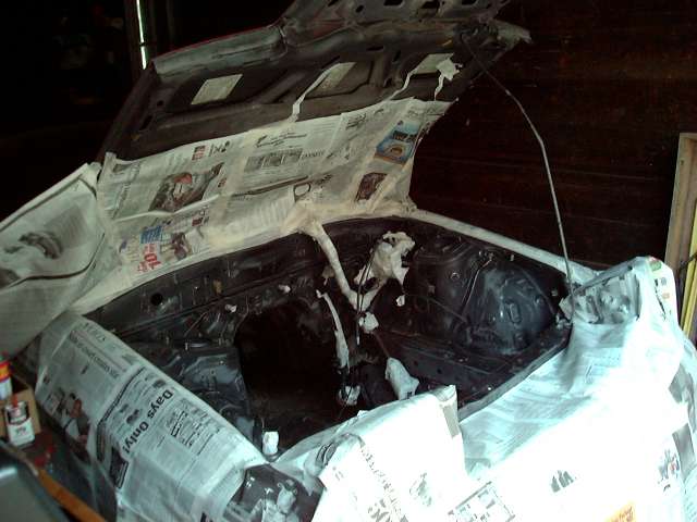
First, it was time to use the good spring weather to strip and paint the engine bay. The purpose of this paint job was not to make it look amazing, but to clean it up and make it roughly match the exterior paint of the car. 16 years of grime, grease, rust and general crap were removed with a wire brush, Castrol Super clean, and effort. 300 grit sandpaper was used to break the exiting finish.
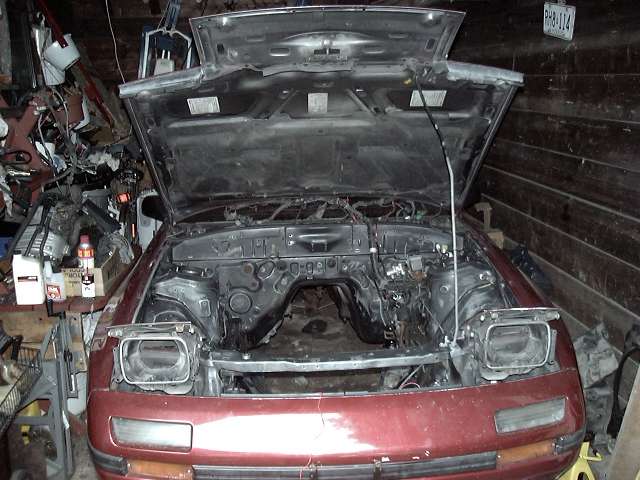
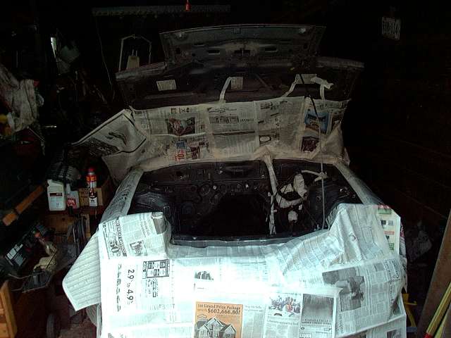
The bay was then masked with newspaper, primed and sprayed. Sorry about the lack of pictures of the primer, I just plain forgot to take them.
I honestly can't say that I put massive amounts of time into the project until early last summer. I had a busy time in my life, with multiple side projects, big meets (can you say Revolution?), and of course my day job. Because of this, work has been slow, with spurts of activity separated by periods of idle time. But anyway, in the past few months I have been working steadily and have some significant progress. So let's get to the pictures already...
When we last left off, the engine was disassembled on the bench. Basically, it sat like that until the fall of 2003, but I'm getting ahead of myself...
First, it was time to use the good spring weather to strip and paint the engine bay. The purpose of this paint job was not to make it look amazing, but to clean it up and make it roughly match the exterior paint of the car. 16 years of grime, grease, rust and general crap were removed with a wire brush, Castrol Super clean, and effort. 300 grit sandpaper was used to break the exiting finish.
The bay was then masked with newspaper, primed and sprayed. Sorry about the lack of pictures of the primer, I just plain forgot to take them.
Last edited by Aaron Cake; Mar 20, 2006 at 09:49 AM.
Thread Starter
Joined: Feb 2001
Posts: 29,798
Likes: 128
From: London, Ontario, Canada
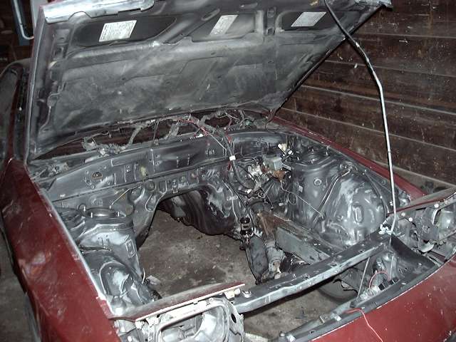
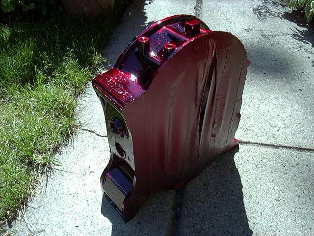
All painted up. For the record, the paint I used was MotoMaster Cherry Red metallic. The primer was Rust Check (this stuff is amazing).
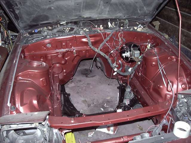
Aside from the engine bay, all the components that are going back under the hood were also cleaned and detailed. This included the leading/trailing coils, charcoal canister, fuse box and bracket, brake booster, hood latch clutch master/slave and a few misc things. The brake master and brake lines will be highlighted black before the engine is dropped back in.
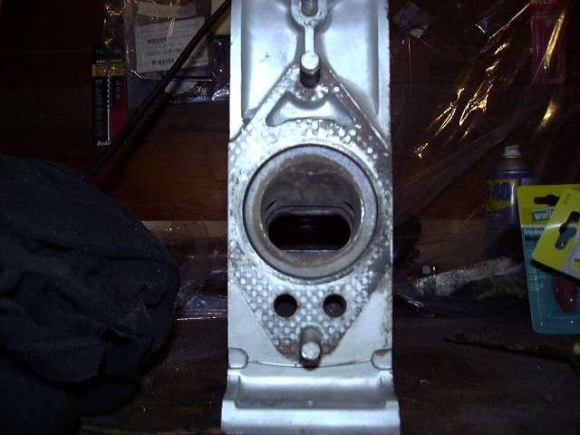
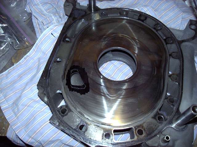
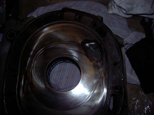
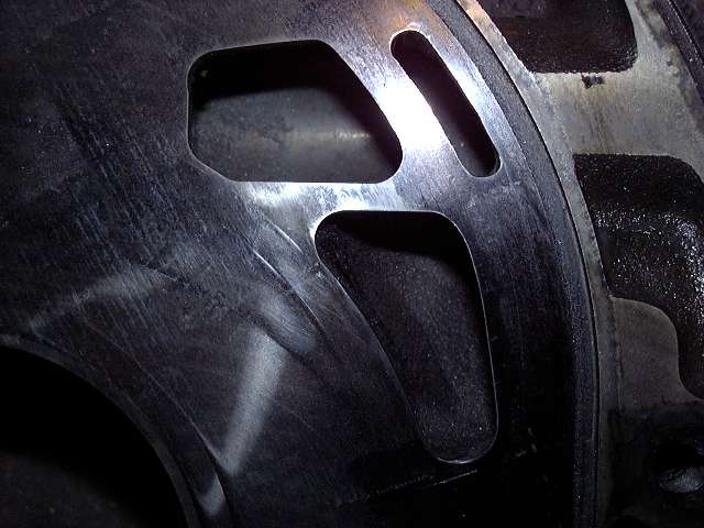
So in the fall of 2003, I finally got around to the actual engine. Here's a few of the stock NA exhaust ports.
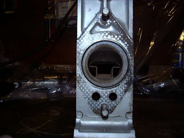
First step is to remove the diffuser present in the NA exhaust ports. I could have just swapped in TII exhaust sleeves, but it's kind of a pain to remove the pins that hold them in and risk damaging the housings.
Aside from the engine bay, all the components that are going back under the hood were also cleaned and detailed. This included the leading/trailing coils, charcoal canister, fuse box and bracket, brake booster, hood latch clutch master/slave and a few misc things. The brake master and brake lines will be highlighted black before the engine is dropped back in.
So in the fall of 2003, I finally got around to the actual engine. Here's a few of the stock NA exhaust ports.
First step is to remove the diffuser present in the NA exhaust ports. I could have just swapped in TII exhaust sleeves, but it's kind of a pain to remove the pins that hold them in and risk damaging the housings.
Last edited by Aaron Cake; Mar 20, 2006 at 09:50 AM.
Thread Starter
Joined: Feb 2001
Posts: 29,798
Likes: 128
From: London, Ontario, Canada
With the diffusers sent to hell where they belong, it was time to start the "real" porting. The first step was to obtain the templates. For the exhaust, I chose the Racing Beat "street" turbo template. It moves the port down to open it sooner, but keeps the top edge in the stock location to help combat overlap. Since no one makes a bridgeport 6-port template, I decided to pick up the Mazdatrix 6 port "street port" template and use it as a base.
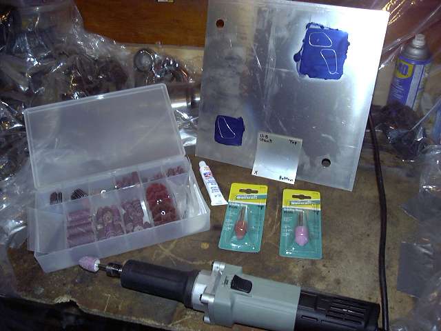
The proper tools are very important. Using an underpowered tool is almost as bad as an overpowered one. The die grinder shown below is an electric unit, with a large 5A motor, 1/4" collet and a 28,000 RPM rating. Various grinding stones, paper rolls and mandrels were a hard thing to find locally, so I ordered the "Deluxe Porting Kit" from Standard Abrasives. It's meant for cylinder head porting, but the abrasives included obviously work with the castings in the rotary as well. The grinding stones are great for removing large amounts of cast metal quickly, while the sandpaper rolls just eat aluminum, and are wonderful for polishing and finish porting.
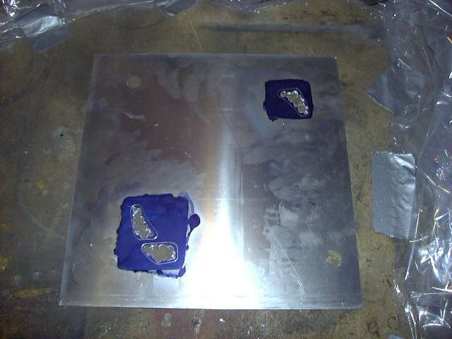
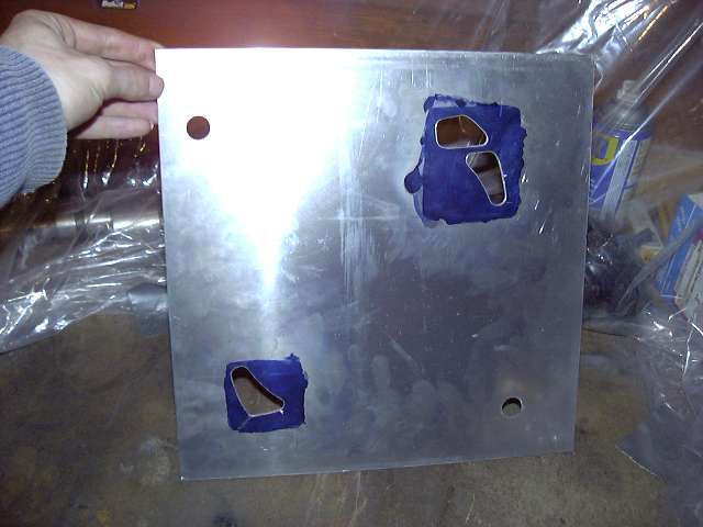
Most templates come as just an outing scribed on sheet metal. It is up to you to actually cut out the pattern. They say that this is to help you "practice" using a die grinder. Yeah, right. I was lazy so I just drilled out the rough shape.
And then finished it off with a paper sanding roll.
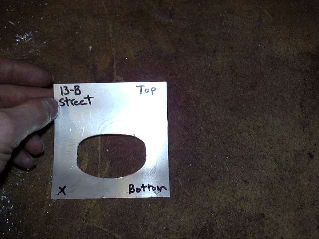
The dowel pin holes are used to locate the top of the template in relation to the exhaust port.

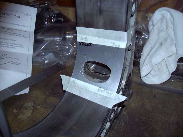
The template was taped in place...
The proper tools are very important. Using an underpowered tool is almost as bad as an overpowered one. The die grinder shown below is an electric unit, with a large 5A motor, 1/4" collet and a 28,000 RPM rating. Various grinding stones, paper rolls and mandrels were a hard thing to find locally, so I ordered the "Deluxe Porting Kit" from Standard Abrasives. It's meant for cylinder head porting, but the abrasives included obviously work with the castings in the rotary as well. The grinding stones are great for removing large amounts of cast metal quickly, while the sandpaper rolls just eat aluminum, and are wonderful for polishing and finish porting.
Most templates come as just an outing scribed on sheet metal. It is up to you to actually cut out the pattern. They say that this is to help you "practice" using a die grinder. Yeah, right.
I was lazy so I just drilled out the rough shape.And then finished it off with a paper sanding roll.
The dowel pin holes are used to locate the top of the template in relation to the exhaust port.
The template was taped in place...
Last edited by Aaron Cake; Mar 20, 2006 at 09:51 AM.
Thread Starter
Joined: Feb 2001
Posts: 29,798
Likes: 128
From: London, Ontario, Canada
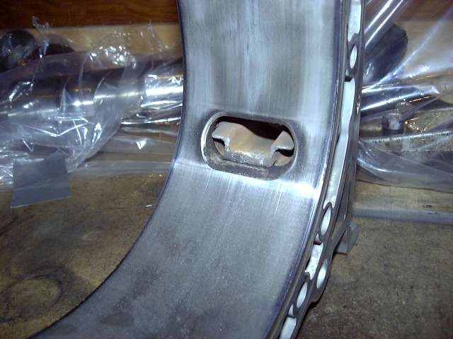
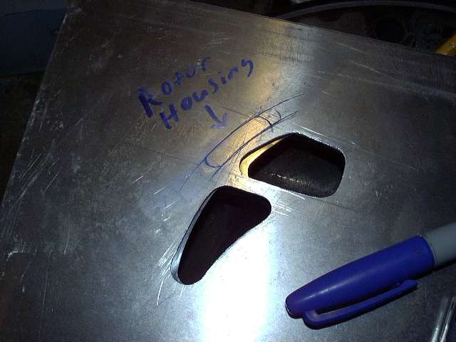
And then the port shape scribed onto the housing. The black magic marker keeps the scribe line visible. Dykem or Machinest's blue is ideal for this, but try as I might I couldn't find any locally. Weird.
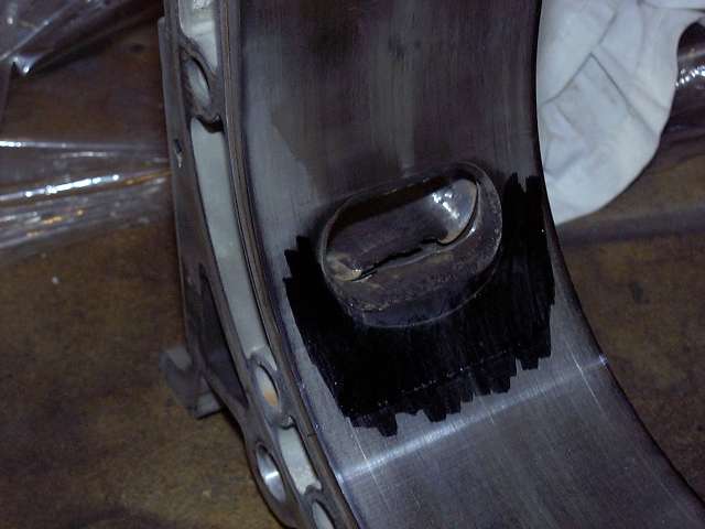
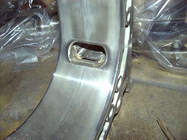
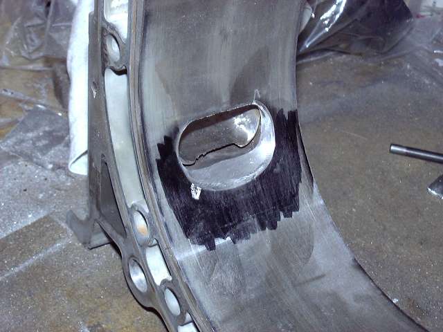
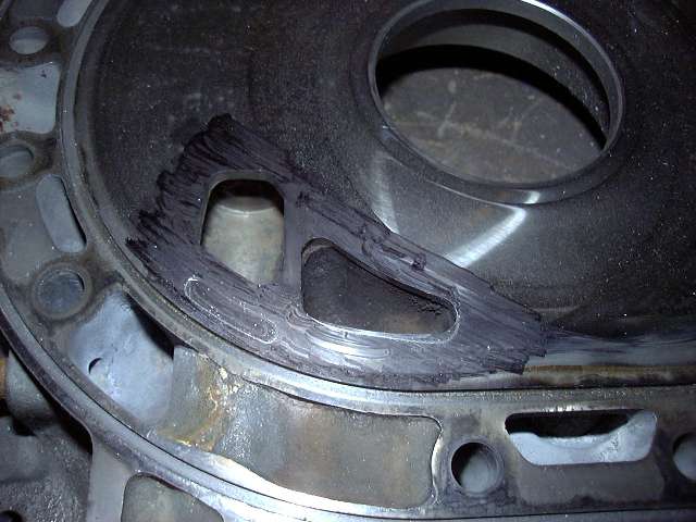
To port the exhausts, I started by using a grinding stone to remove the inner chromed surface down to the level of the scribe. It is very important to leave a bevel like the stock ports have. This avoids a "lip" which can catch the apex seal side. To bring down the aluminum, I used a paper sanding roll. It really works well for this purpose, and leaves an excellent finish. Not something I can say about the carbide bits that many people use. The one disadvantage about the paper rolls is that they can explode. You can see the two scuff marks above and blow the port which were caused by such an explosion. Luckily, they are nothing more then minor surface scuffs, and I don't worry about them.
I also took the sandpaper rolls to the inner surface of the port sleeves and smoothed them out considerably. This should help prevent carbon from sticking.
With the exhaust ports done, it was time to turn my attention to the intake ports. First, the template needed to be cut out. I started by roughly drilling out the area, then took down the aluminum to the lines with a cutting bit, after which I finished off with the paper rolls.
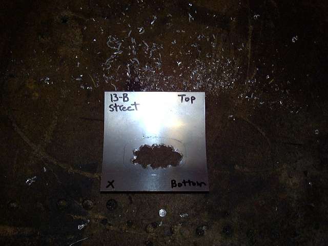
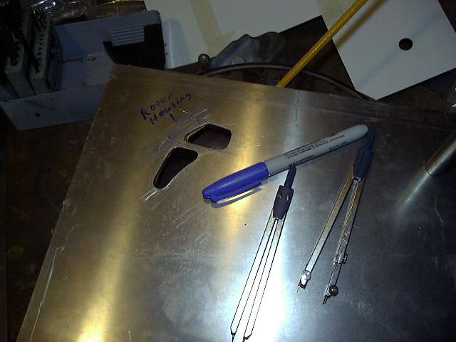
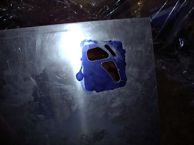
Since there are no 6 port bridge templates available, it was time to make one. The process is fairly simple; first, install a housing on top of an iron, then get a measurement of the width between the housing and the corner seal tracing mark on the iron. This is the width of the new "eyebrow" port. Remove the housing, and lay the template on the iron, then reinstall the housing. Trace a line following the housing. Remove the template, then use a compass to make the inner line by following the outer line. The gap of the compass is the previous width measurement. Close off the top and bottom where it looks "about right" based on the location of the runners and water jacket. The result is the tracing on the template below.
To port the exhausts, I started by using a grinding stone to remove the inner chromed surface down to the level of the scribe. It is very important to leave a bevel like the stock ports have. This avoids a "lip" which can catch the apex seal side. To bring down the aluminum, I used a paper sanding roll. It really works well for this purpose, and leaves an excellent finish. Not something I can say about the carbide bits that many people use. The one disadvantage about the paper rolls is that they can explode. You can see the two scuff marks above and blow the port which were caused by such an explosion. Luckily, they are nothing more then minor surface scuffs, and I don't worry about them.
I also took the sandpaper rolls to the inner surface of the port sleeves and smoothed them out considerably. This should help prevent carbon from sticking.
With the exhaust ports done, it was time to turn my attention to the intake ports. First, the template needed to be cut out. I started by roughly drilling out the area, then took down the aluminum to the lines with a cutting bit, after which I finished off with the paper rolls.
Since there are no 6 port bridge templates available, it was time to make one. The process is fairly simple; first, install a housing on top of an iron, then get a measurement of the width between the housing and the corner seal tracing mark on the iron. This is the width of the new "eyebrow" port. Remove the housing, and lay the template on the iron, then reinstall the housing. Trace a line following the housing. Remove the template, then use a compass to make the inner line by following the outer line. The gap of the compass is the previous width measurement. Close off the top and bottom where it looks "about right" based on the location of the runners and water jacket. The result is the tracing on the template below.
Last edited by Aaron Cake; Mar 20, 2006 at 09:52 AM.
Thread Starter
Joined: Feb 2001
Posts: 29,798
Likes: 128
From: London, Ontario, Canada
And here are the essential tools for making that template.
Time to work on the intermediate housing. You can see how much larger you can make the port. Actually, it can go just a little higher before you start to worry about the water jacket. The lower end can actually be tapered down as well, but here you run into the water jacket very quickly. Note that the port is not moved out at all, so it doesn't open that much sooner.
Primary ports almost done. At this point, they just need a little touch up and polishing. Also, the runners need to be ported (remove the casting flash, smooth the transition to the port, and make them a wee bit bigger). The rough work was done with a large grinding stone, then finished off with a delicate tiny stone. Polishing and smoothing was done with the paper rolls.
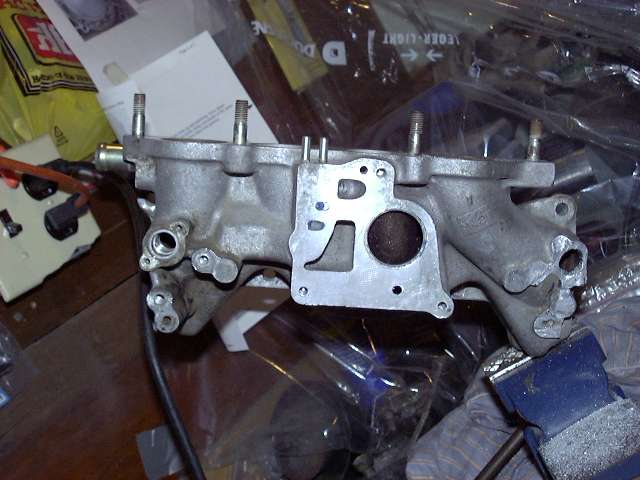
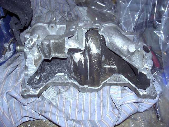
So after the primaries, I got a little bored with the porting and decided to attack the lower intake manifold. Since I no longer have the ACV (it interferes with the turbo), nor any of the other emissions equipment (the Microtech ECU doesn't run it) there is simply no need for the bulk of the lower intake. And frankly, block off plates and the associated solutions are just hacks. Clearance between the turbo and NA lower intake is also very tight, so I decided to simply cut off all the unneeded parts of the manifold. It is amazing how much of the lower intake is just empty space.
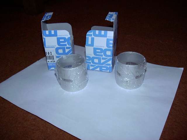
It was about that time that my apex seals and 3 window bearings arrived from Atkins. I chose the Atkins 2 piece 2MM seal, and had them throw in a set of Mazda 3 window main bearings. The bearings are shown below. The stock bearing has one oil hole that is fed by oil passage in the stationary gear. These holes sit at the top of the bearing, and are the eccentric shaft's only source of oil. So in a stock engine, the stationary bearings, rotor bearings, eccentric shaft and eccentric oil jets are lubricated by oil from an opening in the bearing about as thick as a pencil. The three window bearings each have three oil passages, hence the name. This assures a much better flow of oil to the eccentric and associated parts. However, installation requires modification of the stationary gears, which I will explain later on. Sorry, but no pictures of the apex seals. We've all seen apex seals, right?
Time to work on the intermediate housing. You can see how much larger you can make the port. Actually, it can go just a little higher before you start to worry about the water jacket. The lower end can actually be tapered down as well, but here you run into the water jacket very quickly. Note that the port is not moved out at all, so it doesn't open that much sooner.
Primary ports almost done. At this point, they just need a little touch up and polishing. Also, the runners need to be ported (remove the casting flash, smooth the transition to the port, and make them a wee bit bigger). The rough work was done with a large grinding stone, then finished off with a delicate tiny stone. Polishing and smoothing was done with the paper rolls.
So after the primaries, I got a little bored with the porting and decided to attack the lower intake manifold. Since I no longer have the ACV (it interferes with the turbo), nor any of the other emissions equipment (the Microtech ECU doesn't run it) there is simply no need for the bulk of the lower intake. And frankly, block off plates and the associated solutions are just hacks. Clearance between the turbo and NA lower intake is also very tight, so I decided to simply cut off all the unneeded parts of the manifold. It is amazing how much of the lower intake is just empty space.
It was about that time that my apex seals and 3 window bearings arrived from Atkins. I chose the Atkins 2 piece 2MM seal, and had them throw in a set of Mazda 3 window main bearings. The bearings are shown below. The stock bearing has one oil hole that is fed by oil passage in the stationary gear. These holes sit at the top of the bearing, and are the eccentric shaft's only source of oil. So in a stock engine, the stationary bearings, rotor bearings, eccentric shaft and eccentric oil jets are lubricated by oil from an opening in the bearing about as thick as a pencil. The three window bearings each have three oil passages, hence the name. This assures a much better flow of oil to the eccentric and associated parts. However, installation requires modification of the stationary gears, which I will explain later on. Sorry, but no pictures of the apex seals. We've all seen apex seals, right?
Last edited by Aaron Cake; Mar 20, 2006 at 09:52 AM.
Thread Starter
Joined: Feb 2001
Posts: 29,798
Likes: 128
From: London, Ontario, Canada
So back to the intake. The 6 port actuator supports and rod bushing area was cut off. The 6 port actuators are not needed in a turbo application, and frankly, they won't physically fit.
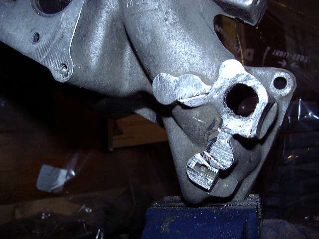
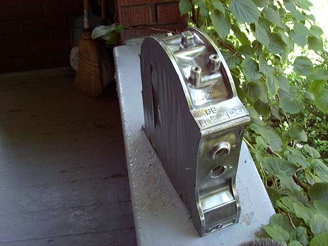
Beginning to remove the emissions passages on the lower half of the intake. You can see the empty space starting to show.
Removing the ACV mount.
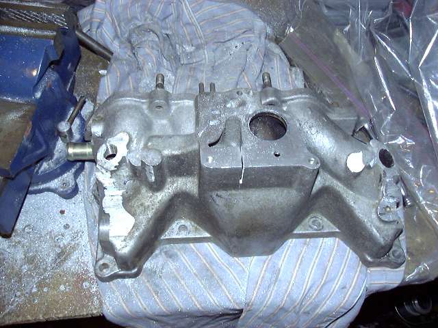
Now here is the NA lower intake with all the emissions passages removed. You can see the massive amount of empty space inside the casting. What did strike me was how well the whole thing was designed. See, the air from the air pump flows through the ACV, and into either the cat (during 5th gear cruise), into the exhaust ports (during regular driving) or into the rear rotor (during decel). In order to get into the exhaust ports, the air must flow over all the lower intake runners. I am sure that this has a major cooling effect on the air being taken in by the engine. Whether this makes a difference in "off the line", I can't say. But seeing the inner workings of the manifold is pretty cool. The final manifold will have all the rough edges taken off and be painted to match the rest of the engine. Also, the holes have since been TIG welded shut, but I don't have pictures of that (yet).
Beginning to remove the emissions passages on the lower half of the intake. You can see the empty space starting to show.
Removing the ACV mount.
Now here is the NA lower intake with all the emissions passages removed. You can see the massive amount of empty space inside the casting. What did strike me was how well the whole thing was designed. See, the air from the air pump flows through the ACV, and into either the cat (during 5th gear cruise), into the exhaust ports (during regular driving) or into the rear rotor (during decel). In order to get into the exhaust ports, the air must flow over all the lower intake runners. I am sure that this has a major cooling effect on the air being taken in by the engine. Whether this makes a difference in "off the line", I can't say. But seeing the inner workings of the manifold is pretty cool. The final manifold will have all the rough edges taken off and be painted to match the rest of the engine. Also, the holes have since been TIG welded shut, but I don't have pictures of that (yet).
Last edited by Aaron Cake; Mar 20, 2006 at 09:53 AM.
Thread Starter
Joined: Feb 2001
Posts: 29,798
Likes: 128
From: London, Ontario, Canada
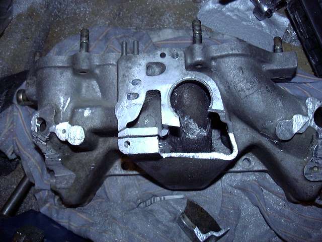
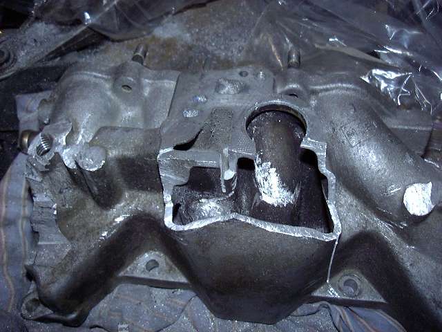
Another picture of the intake.

OK, lets get back to the serious work. Here's the intake port template with the "eyebrow" cut out. It's a fairly poor picture, and the port looks much better in person. The port was drilled out, then ported using a Dremel tool and a spiral cutting bit. The bridgeports are much too small to do with the big die grinder.
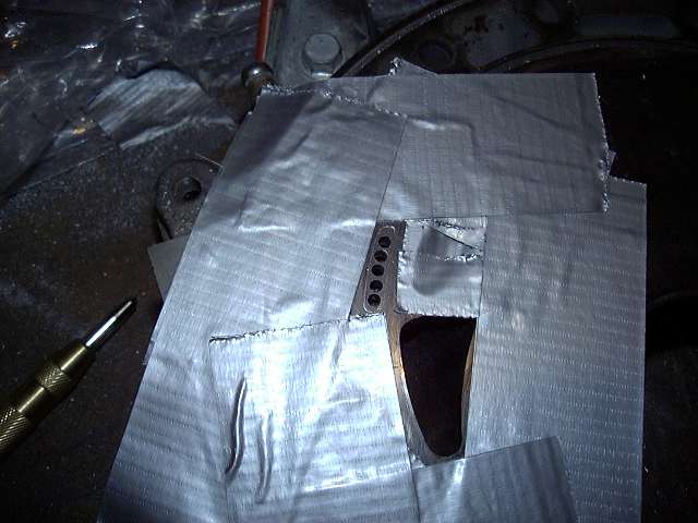
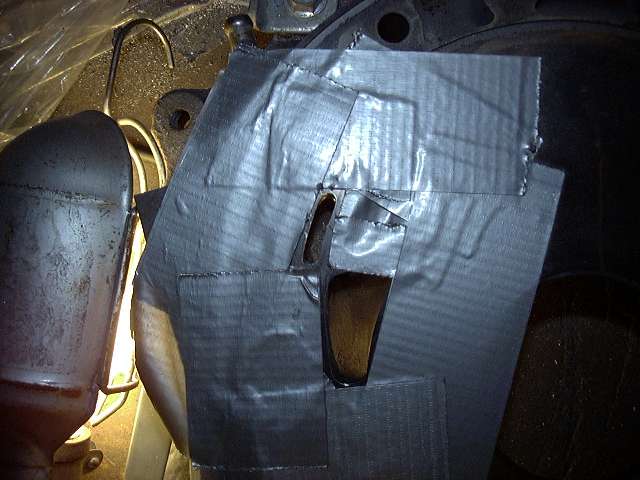
These two pictures show the ports scribed onto the housing. Note the aux (the "5th and 6th ports") are being left untouched. The secondary port is only being moved towards the outside a little.

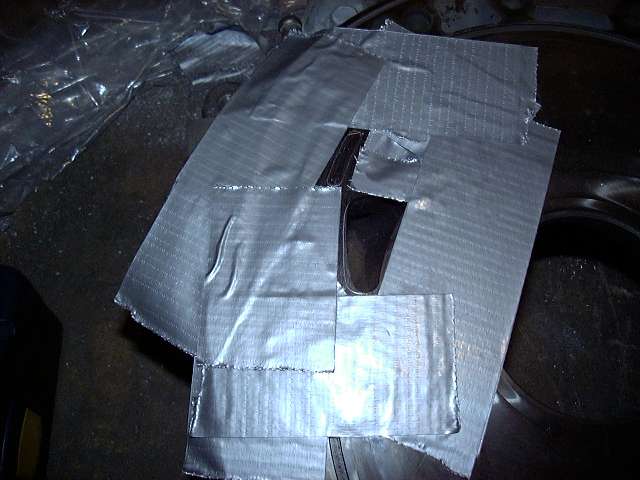
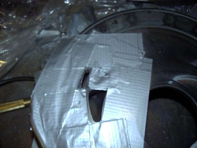
Very important to mask everything off before porting. That's about 4 layers of duct tape.
OK, lets get back to the serious work. Here's the intake port template with the "eyebrow" cut out. It's a fairly poor picture, and the port looks much better in person. The port was drilled out, then ported using a Dremel tool and a spiral cutting bit. The bridgeports are much too small to do with the big die grinder.
These two pictures show the ports scribed onto the housing. Note the aux (the "5th and 6th ports") are being left untouched. The secondary port is only being moved towards the outside a little.
Very important to mask everything off before porting. That's about 4 layers of duct tape.
Last edited by Aaron Cake; Mar 20, 2006 at 09:55 AM.
Trending Topics
Thread Starter
Joined: Feb 2001
Posts: 29,798
Likes: 128
From: London, Ontario, Canada
To start a bridgeport, you first drill out the rough shape with a 3/16th drill bit. I started with one size smaller, center punching first. I then enlarged the hole.
The "eyebrow" was created using a dremel tool and very thin grinding stone. It took some time, but also made it very difficult to screw up. That's the thing about the die grinder: it will just eat through anything. There is no forgiveness. However, the Dremel works slowly and requires you to take breaks. However, it is more difficult to get a uniform cut with the Dremel because the bits are so small.
Here's the end result of the bridge and the secondary ported.
And is the scribe on the opposite iron.
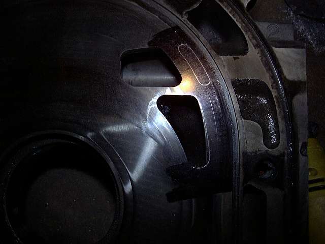
And the port is finished.
The "eyebrow" was created using a dremel tool and very thin grinding stone. It took some time, but also made it very difficult to screw up. That's the thing about the die grinder: it will just eat through anything. There is no forgiveness. However, the Dremel works slowly and requires you to take breaks. However, it is more difficult to get a uniform cut with the Dremel because the bits are so small.
Here's the end result of the bridge and the secondary ported.
And is the scribe on the opposite iron.
And the port is finished.
Last edited by Aaron Cake; Mar 20, 2006 at 09:55 AM.
Thread Starter
Joined: Feb 2001
Posts: 29,798
Likes: 128
From: London, Ontario, Canada
At this point, the major modifications are done. Now it's time to clean. And clean. And clean, and clean, and clean. Then some cleaning took place, after which there was cleaning. Following that, I cleaned. OK, you get the point. In order to get the finish I wanted on the rotor housings, they were given a quick and dirty polish. Ahhhh, shiny...
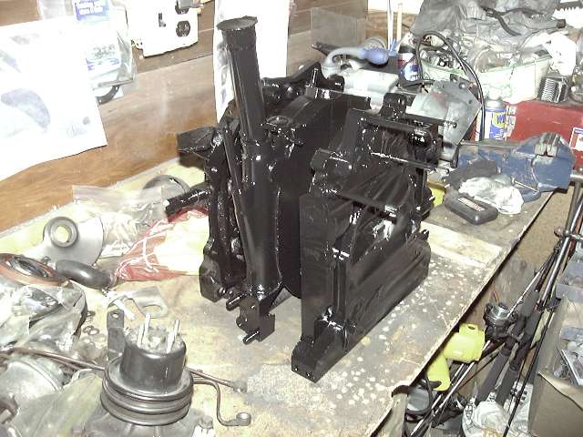
While I was dealing with the housings, I also masked and painted the irons. They were masked off with duct tape (Note: if you do this, use masking tape. Much easier and cleaner to remove) and painted with VHT gloss black. It's a brake caliper enamel that is good to about 600 degrees or so. Also very chemical resistant. It worked so well on silverrotor's engine that I decided to also use it on mine.
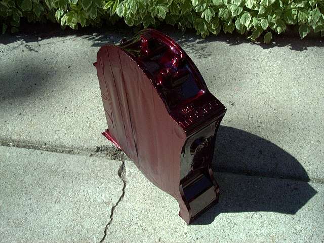
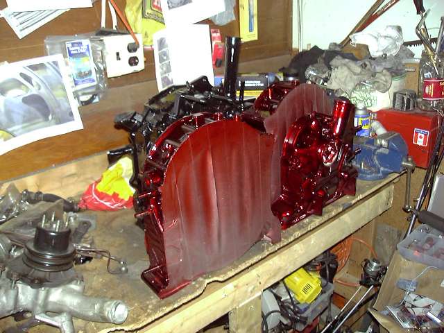
Each rotor housing was given 4 coats of Dupont's MetalCast in red. I must say that the result was bloody brilliant. The housings took on a life of their own. You can see every detail of the metal through the candy coating, and in sunlight it's just like looking into a pool of blood. Very cool. The "Mazda" logos will be highlighted in black.
So here are the stationary gears with installed three window bearings. Installation is simple, but requires some machine work. First, the old bearing is pressed out. In order for each window of the new bearings to receive oil, a channel must be cut on the inner side of the stationary gear. This channel is about 5-8MM wide (exact dimensions are unimportant), 1.5MM deep (don't go to deep otherwise you weaken the gear) and in line with the oil feed hole. When the bearing is pressed in, the windows roughly line up with the channel, thus feeding the windows with pressurized oil. I don't doubt that someone somewhere has made this channel with a Dremel tool, but really, it needs to be done on a lathe. I just sent my gears to a local machine shop. The entire operation cost $40. The new bearings were then pressed in.

While I was dealing with the housings, I also masked and painted the irons. They were masked off with duct tape (Note: if you do this, use masking tape. Much easier and cleaner to remove) and painted with VHT gloss black. It's a brake caliper enamel that is good to about 600 degrees or so. Also very chemical resistant. It worked so well on silverrotor's engine that I decided to also use it on mine.
Each rotor housing was given 4 coats of Dupont's MetalCast in red. I must say that the result was bloody brilliant. The housings took on a life of their own. You can see every detail of the metal through the candy coating, and in sunlight it's just like looking into a pool of blood. Very cool. The "Mazda" logos will be highlighted in black.
So here are the stationary gears with installed three window bearings. Installation is simple, but requires some machine work. First, the old bearing is pressed out. In order for each window of the new bearings to receive oil, a channel must be cut on the inner side of the stationary gear. This channel is about 5-8MM wide (exact dimensions are unimportant), 1.5MM deep (don't go to deep otherwise you weaken the gear) and in line with the oil feed hole. When the bearing is pressed in, the windows roughly line up with the channel, thus feeding the windows with pressurized oil. I don't doubt that someone somewhere has made this channel with a Dremel tool, but really, it needs to be done on a lathe. I just sent my gears to a local machine shop. The entire operation cost $40. The new bearings were then pressed in.
Last edited by Aaron Cake; Mar 20, 2006 at 09:56 AM.
Thread Starter
Joined: Feb 2001
Posts: 29,798
Likes: 128
From: London, Ontario, Canada
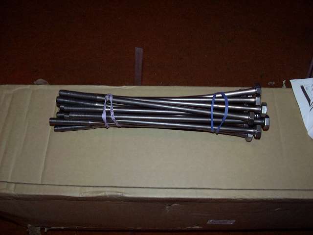
Oh yeah, all the other engine parts need to be spotless as well. Tension bolts, counterweight, eccentric, stationary gears, chain, oil pump, sprockets, spacer assembly, etc., etc. Shown here are the cleaned up tension bolts. Amazing what a wire brush can do to 18 year old bolts.
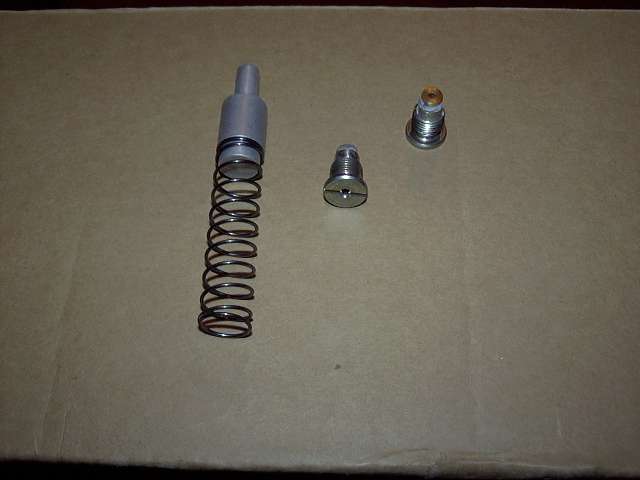
The thermal pellet and modded eccentric oil jets. The thermal pellet eliminates the stock thermostat at the front of the eccentric, assuring a constant supply of oil to the eccentric oil jets. These jets have been modified. A #200 Weber air jet has been installed in place of the stock check ball assembly. The result is increased cooling spray to the inside of the rotors at the sacrifice of some low RPM oil pressure. It's a tradeoff that I willing to accept.
Finally, all the engine parts painted up and ready to go.
So that's it. The engine is now ready to be assembled, which will take place this weekend. I'm fairly excited, seeing as how this has been 2 years in the making. The engine will be assembled in my basement, then the short block brought up to the garage where the accessories will be installed. Then it will be dropped into the car. I still need to get my flywheel resurfaced and pick up a clutch before that though. And the lower intake needs to be finished (it has to go on before the turbo). But regardless, the project is FINALLY starting to come together. I am really hoping to fire her up before the snow flies.
Questions, comments, snide remarks?
(And yes, my website is down right now. Should be back up tomorrow, or by early next week).
Last edited by Aaron Cake; Mar 20, 2006 at 09:57 AM.
Thread Starter
Joined: Feb 2001
Posts: 29,798
Likes: 128
From: London, Ontario, Canada
Originally posted by RX-Heven
Looks like fun. Tha thing should be a beast. What rotors are you using?
Looks like fun. Tha thing should be a beast. What rotors are you using?
I didn't take pictures of the rotors because everyone has already seen rotors before...If you need them, picture a fairly clean rotor with a new bearing. 
Zoom Zoom Boom!
Joined: Mar 2003
Posts: 2,312
Likes: 0
From: San Francisco, CA
Cool project!
I'm in the same boat as well. Stripping out the engine bay and repainting it. Plus rebuilding the engine while I'm at it with a streetport. Can't add the goodies yet though since I have to smog it.
Any tips that will make my life easier when I strip the engine bay and paint it?
I'm in the same boat as well. Stripping out the engine bay and repainting it. Plus rebuilding the engine while I'm at it with a streetport. Can't add the goodies yet though since I have to smog it.
Any tips that will make my life easier when I strip the engine bay and paint it?
Thread Starter
Joined: Feb 2001
Posts: 29,798
Likes: 128
From: London, Ontario, Canada
Originally posted by Travelintrevor
question...could you use a dremel(the one that spins 35,000rpm) to do the porting? or is it not powerful enough? Thanks
question...could you use a dremel(the one that spins 35,000rpm) to do the porting? or is it not powerful enough? Thanks
Seriously, you can. It will just take longer. And with the smaller bits, it's harder to get a uniform shape.
Any tips that will make my life easier when I strip the engine bay and paint it?

I'm bastardizing my car!
Joined: Sep 2002
Posts: 1,258
Likes: 0
From: Naperville, IL.
well.. this is really going above and beyond. I have to ask, whats the port area difference between the turbo housing vs. the N/A one. This is really neat that your doing this with a N/A engine.

Thread Starter
Joined: Feb 2001
Posts: 29,798
Likes: 128
From: London, Ontario, Canada
Originally posted by apreludem
can't see the pics =\
can't see the pics =\
I have to ask, whats the port area difference between the turbo housing vs. the N/A one. This is really neat that your doing this with a N/A engine.
What exactly did you do to get the diffuser out?

i am legendary
Joined: Sep 2003
Posts: 8,478
Likes: 1
From: Kirkland, WA
Haha! Did that take a while? I've read a lot of things about people trying to get the diffusers out and saying how impossible it was. Hopefully I'm going to be pulling my motor in the next month or two to do a huge streetport and rebuild and during that I was going to take the diffuser out for prep when I go turbo.
Thread Starter
Joined: Feb 2001
Posts: 29,798
Likes: 128
From: London, Ontario, Canada
Originally posted by dDuB
Haha! Did that take a while?
Haha! Did that take a while?