When you click on links to various merchants on this site and make a purchase, this can result in this site earning a commission. Affiliate programs and affiliations include, but are not limited to, the eBay Partner Network.
you mentioned searching for an alternator bracket?
what is wrong with the one on the setup right now,..did you find one?..
You can use a 3rd gen alt(Ford) with the 1st gen ford 302 bracket,it just requires some trimming on the cast.
*I may be off on Gens..(I'm an Fc guy remember..heh!)
I did find a new alternator bracket. I decided to go with a new-aftermarket one from Late Model Restorations. I think it was about $65, which is pretty much what everyone on Craigslist and EBay were selling their used ones for. The LMR part appears to be good quality, it at least bolted up in place.
All of the accessory parts are roughly set in place. I wanted to make sure my fuel hoses were going to clear everything.
man o man your engine fits well. i love the stainless hoses
your dist, what type is it that uses a outside coil.
thanks
gordie
Thanks for the kind words Gordie. The distributor is the stock Ford TFI ignition from the 1993 Mustang. It utilizes a remotely mounted coil. The Mustang had the coil mounted near the LF strut tower. I will either do the same on the seven or possible mount it on the engine.
So here is a little more in depth update to what I have been up over the last week. I started off my vacation with big plans to get a lot of different things accomplished, but these plans turned out to be a little too ambitious. I spent a good solid 3 or 4 days working on fuel lines in the engine bay. It turns out bending and flaring hoses takes some time to learn.
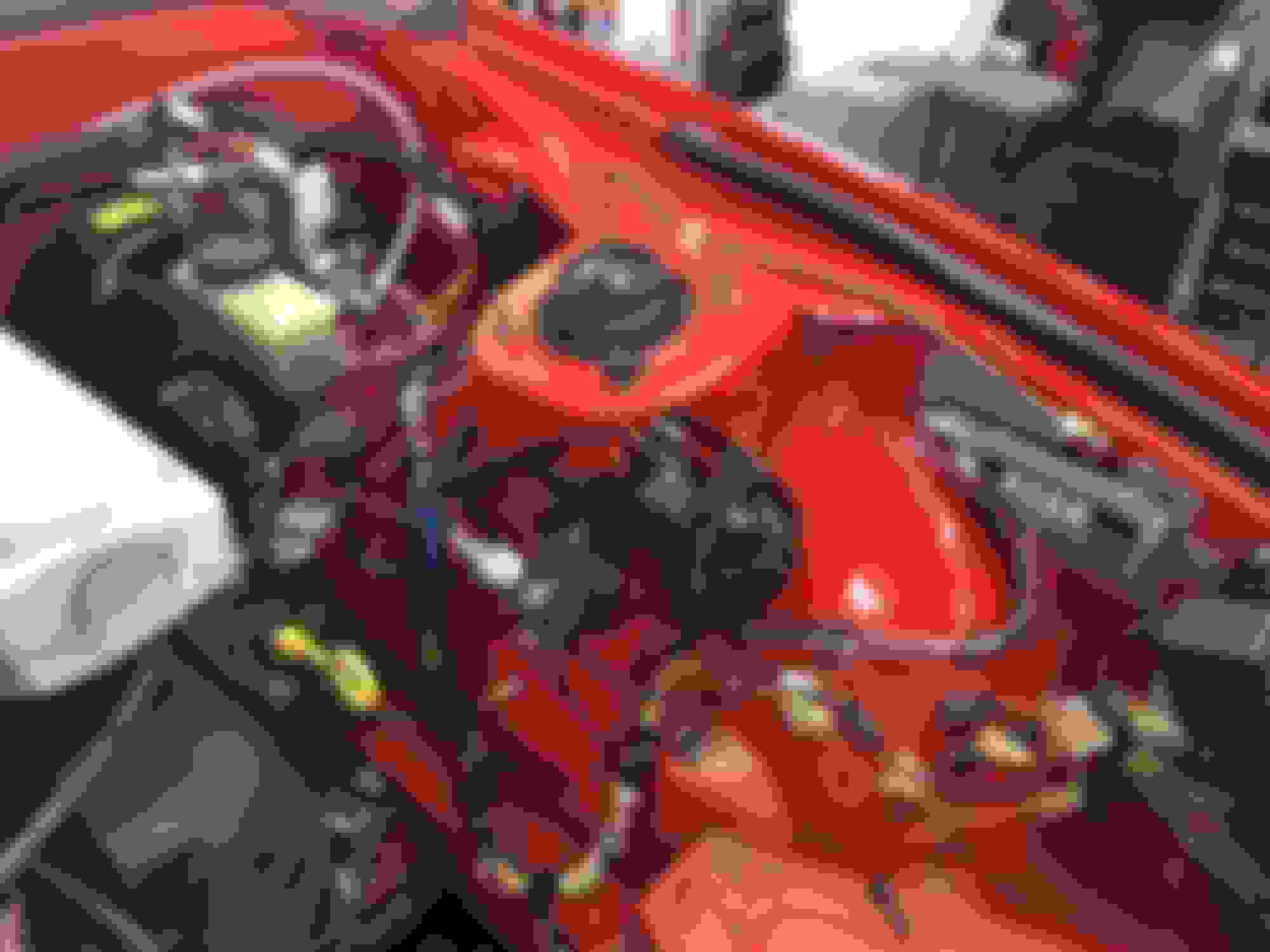
I made a total of 3 lines for the engine compartment (pressure, return and EVAP). The pressure line was my first and most difficult line. I started by cutting off the OE Mazda line near where it terminate in the center of the engine bay. I flared the line and used a coupler to join it to a new 5/16” steel line from Summit Racing. From there I ran the new line over to the right side of the engine bay by the base of the right strut tower. I joined it to a fuel filter with -6AN connections. From there it was Summit’s PTFE braided hose up to the fuel rail where I used Russell’s Ford EFI-to-AN adaptor.
Fuel Filter at base of strut tower.
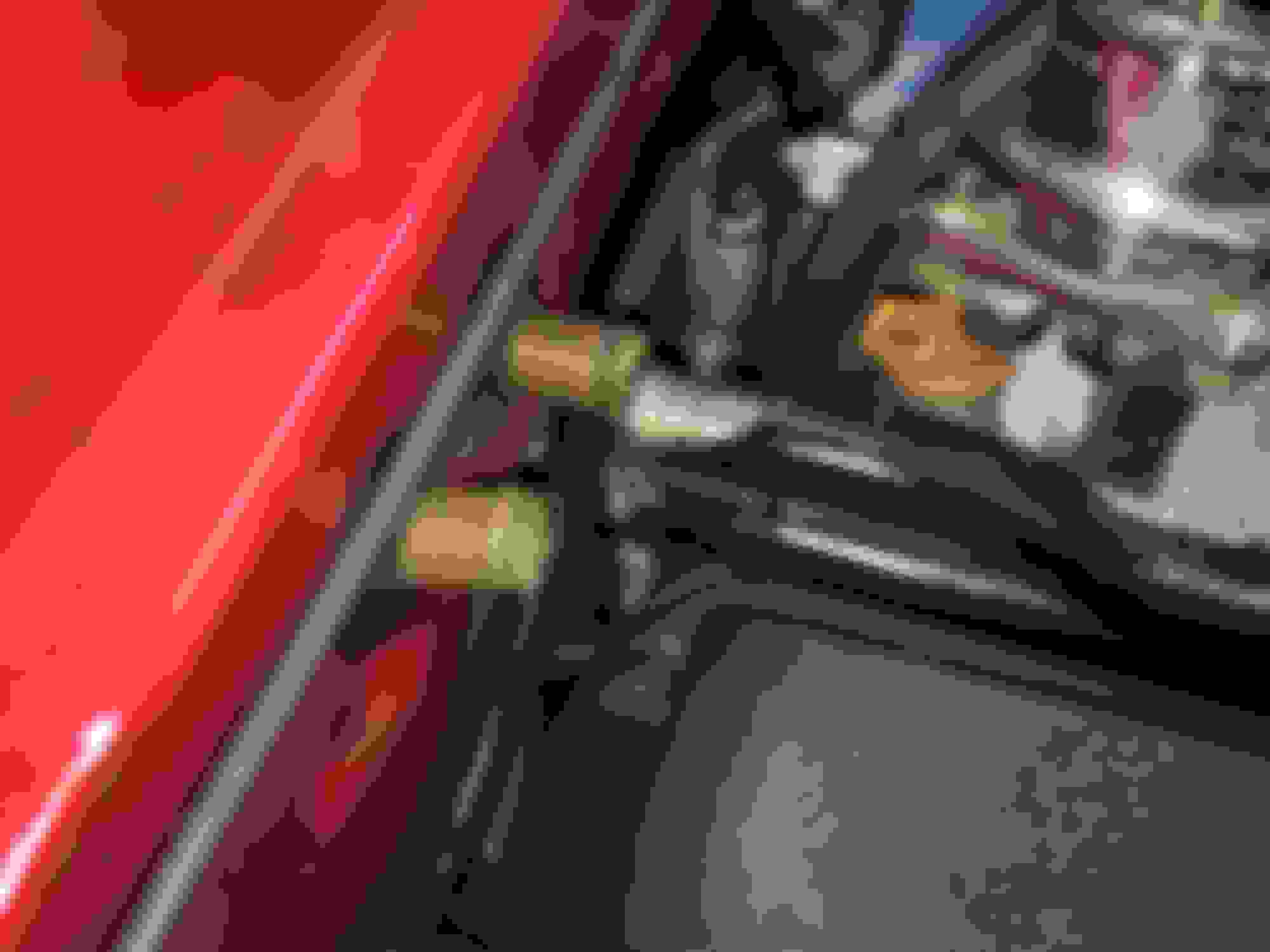
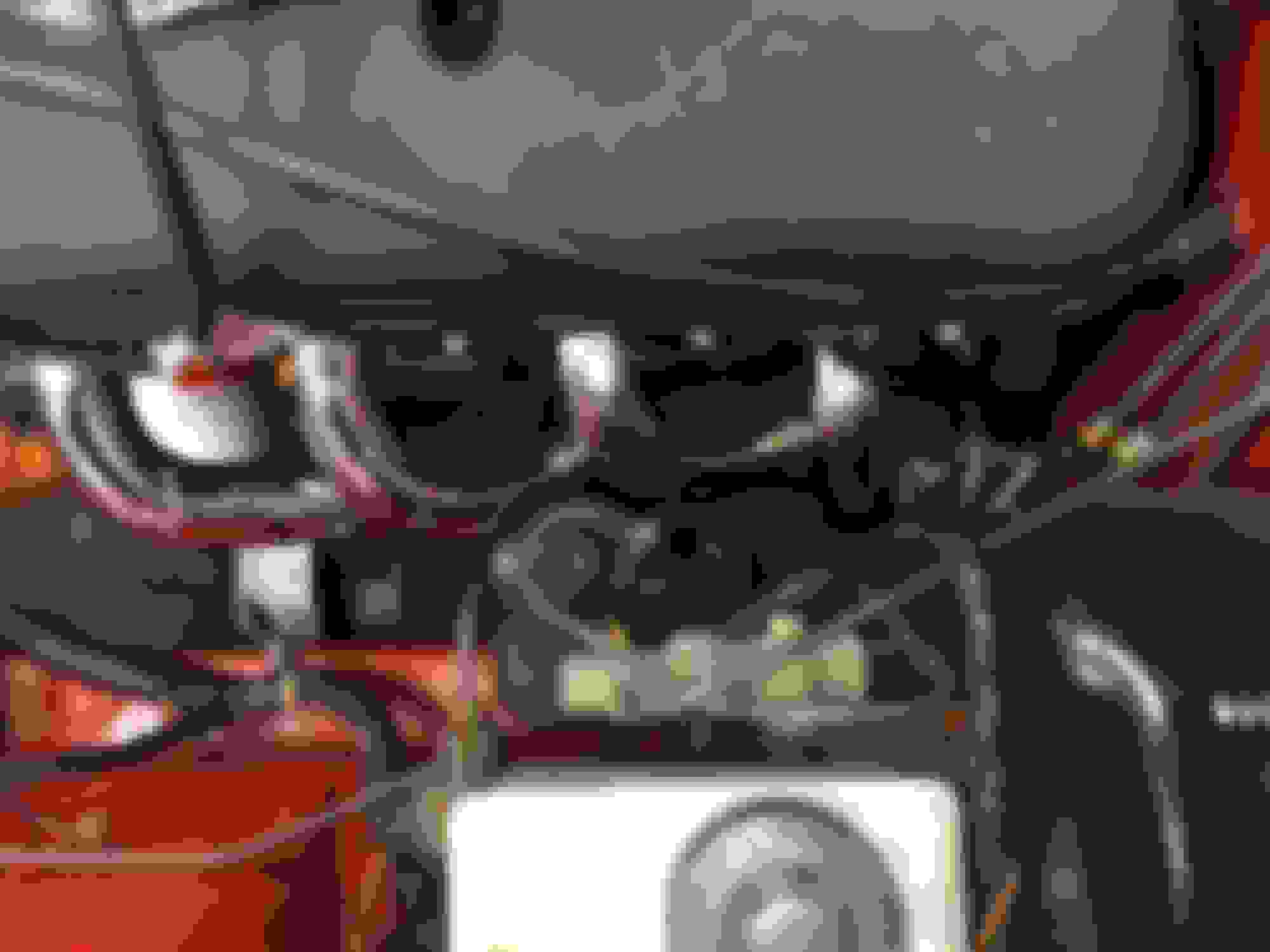
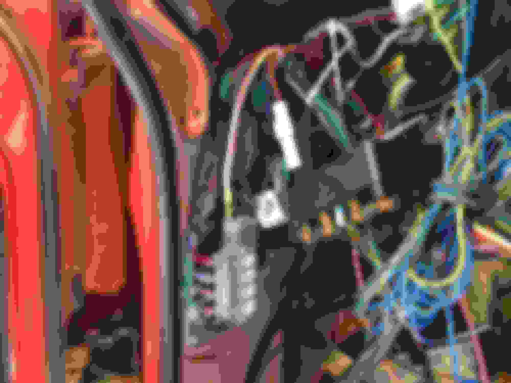
My next line was the return line. If you remember back a month ago I mentioned that all of the fuel lines interfered with the header flange. To correct for this all of the fuel lines were relocated over to the left of the engine bay. The circled area below shows where the original fuel line routing was and where they are now.
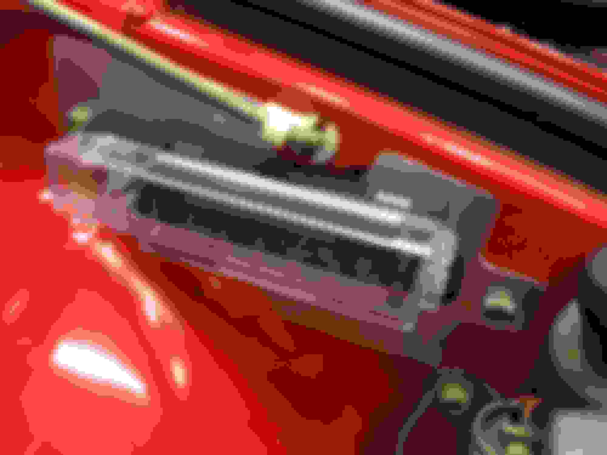
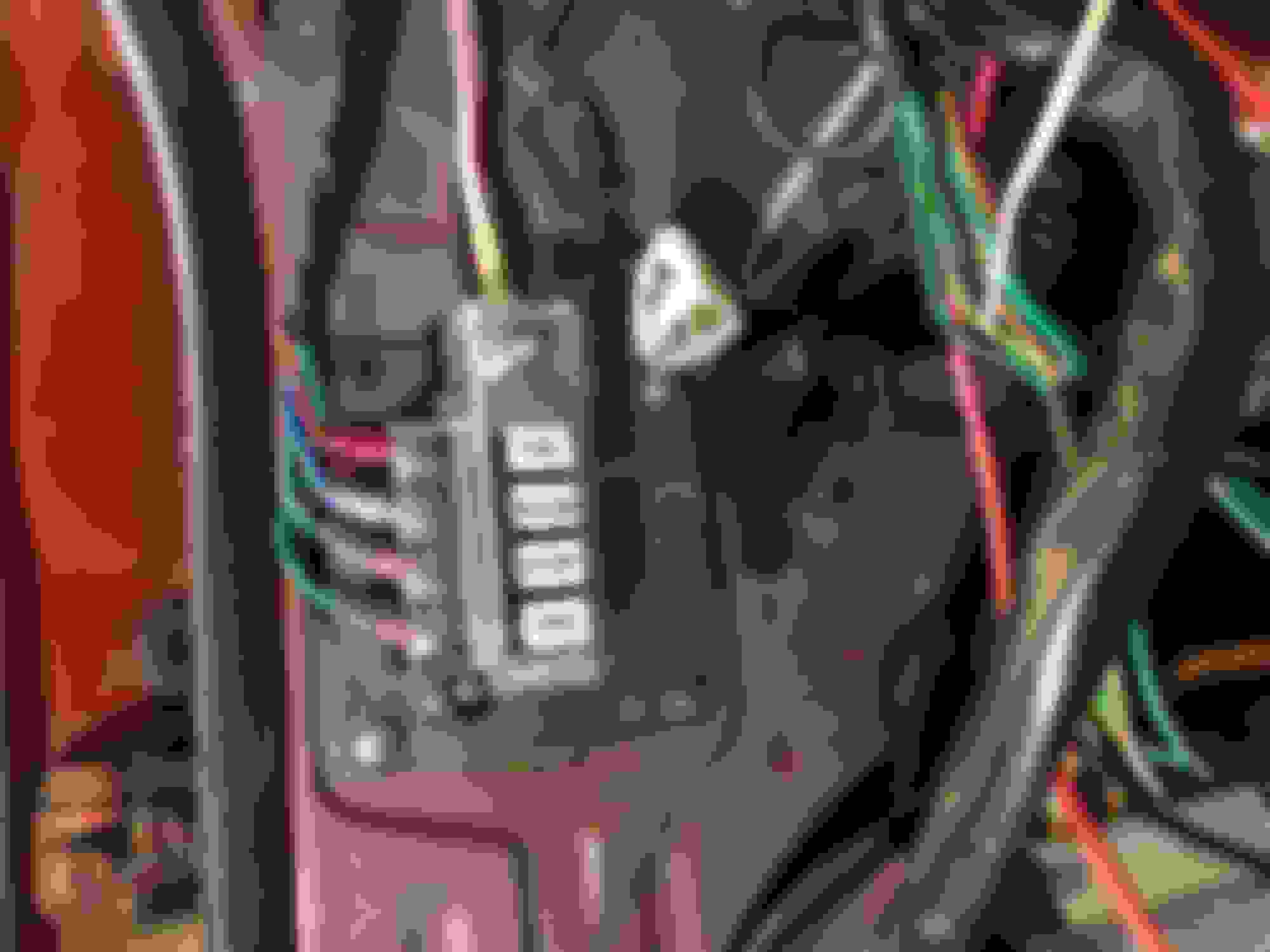
Because there was a narrow space for 3 fuel lines and one brake line to occupy I had to stack the fuel lines on top of one another. I did this by using stock Mazda clamps and 1” steel strips between the layers to act as a base. It goes fuel/brake line – Mazda clamp – steel strip –fuel lines – Mazda clamp. I’m pretty happy with this work around. It looks semi-OEM, which is what I was kind of going for. None-to-less, it was cheap and easy. To aid with installation I threaded 6x1.0mm studs into the original bolt holes and used a nut to secure them tight.
Close up of the fuel lines stacked up.
The return line uses similar connections as the pressure lines and follows a similar path to where the filter is and then more braided hose to the fuel rail where it secures to another Russell adaptor. The EVAP lines is basically the same as the return line but ends with a standard clamp on hose end to attach a vacuum hose to later (EVAP canister). Both the return and EVAP lines were made using Summit’s 1/4 “ steel tubing.I did not get to finish mounting the fuel pump unfortunately. I am short and -6AN hose end and I also need to make a mounting bracket. I need to create a bracket to keep the fuel pump as parallel to the hard line as possible. The bracket will be pretty simple. It will secure to the car where the original Mazda fuel pump bracket did and will place the pump about as high as close to the frame rail as it can go.
After I finish up mocking the pump I will take everything back apart, flush the lines, clean the marker off the lines and clean and paint all the brackets.
Upcoming tasks:
Finish fuel system and reinstall the tank.
Finish clearance the firewall and reinstall the LH header.
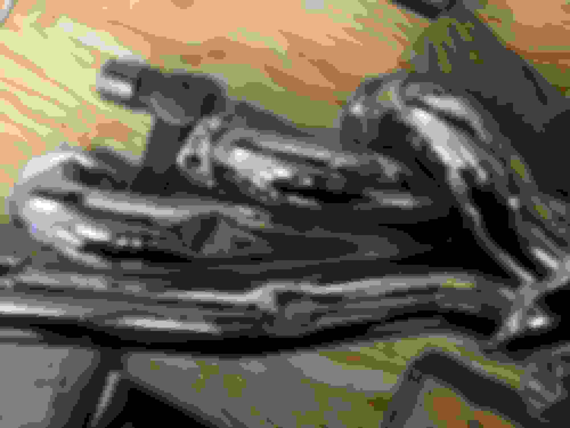
I managed to get a few hours of work in this weekend. I started off by making a short section of braded hose for between the pump and the body hardline. I would have liked to have the pump sit a little further forward but unfortunately this was the shortest section of hose I could make. The braded hose ends take a lot of space up.
After making the hose, I proceeded with making the mounting bracket. I started off by tracing the pattern onto a 10x18� sheet of 16ga steel. I cut out the shape using skill saw and then sanded and grinded the edges smooth. I then drilled out the mounting holes and proceeded with putting the 90 degree bend in.
The finished product came out pretty well. The fuel system is done now in terms of fabrication/modifications. I will take all the lines off one more time, flush and clean them, and then paint all the brackets I made to make them look pretty and prevent them from rusting up.
I�m now starting to look to look for the next big projects. I think the next two big things are to finish up the cooling system and the electrical. To do the cooling I need to determine how I am going to cool the engine. I absolutely don�t want to run a solid flex fan � robs too much engine power. But I�m screwed in terms of space between the radiator and the water pump on the engine side � 1.75�. This eliminates the use of a clutch fan, which forces me to an electric fan. Unfortunately, there doesn�t seem to be any puller fans that fit within the 1.75� clearance. My thoughts are to possibly run two 8� pusher fans. The core itself is a square 18�, but the tube in front of the radiator keeps me from running one big fan.
Anyone that has done a first gen Granny�s V8 swap I would be curious to know how you kept your engine cool. A little disappointed in the lack of space.
To do the electrical I want to determine the cooling system first so I can keep the fan wiring looking clean. I think I have also decided to proceed with a trunk mounted battery and pull the harness apart to eliminate the unneeded wires. Can anybody tell me how difficult it is to remove the engine/front harness? I am mostly concerned with the connections on the inside. Do I have to pull the dash? Connections easy to get to? Some input would be much appreciated. I know some of you have done a wire tuck and have had to do this.
. Less than 1.75" of clearance between water pump and radiator core.Look forward to everyone advice and thoughts on cooling fans and removal of the engine bay/front harness.
JJ
Last edited by Yolo7; Dec 3, 2017 at 07:40 PM.
Reason: font formatting
Go with 2 fans and make or buy a shroud for them. Make sure you have bypass flaps for highway speed as well. I would also get Spal or similar high quality fans, they move a lot more air than the $30 cheapies. Harness Pull should be straight forward. Take out the seats and you won't have to pull the dash at all. Be gentle with the connnections and everything should be fine. If you do cut anything make sure you leave enough wire on the connector end to crimp back if you need to.
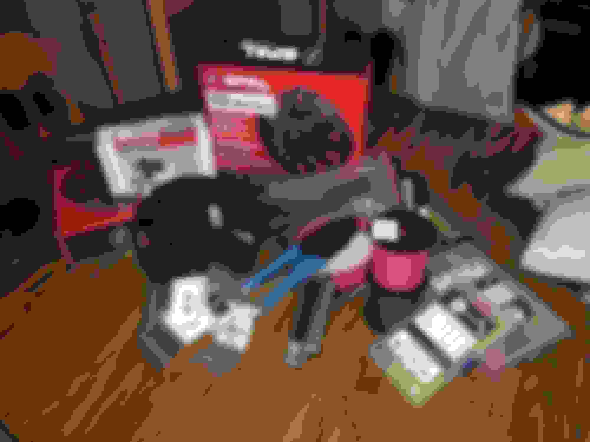
A few more goodies and progress to report on. I received a couple of packages this week.
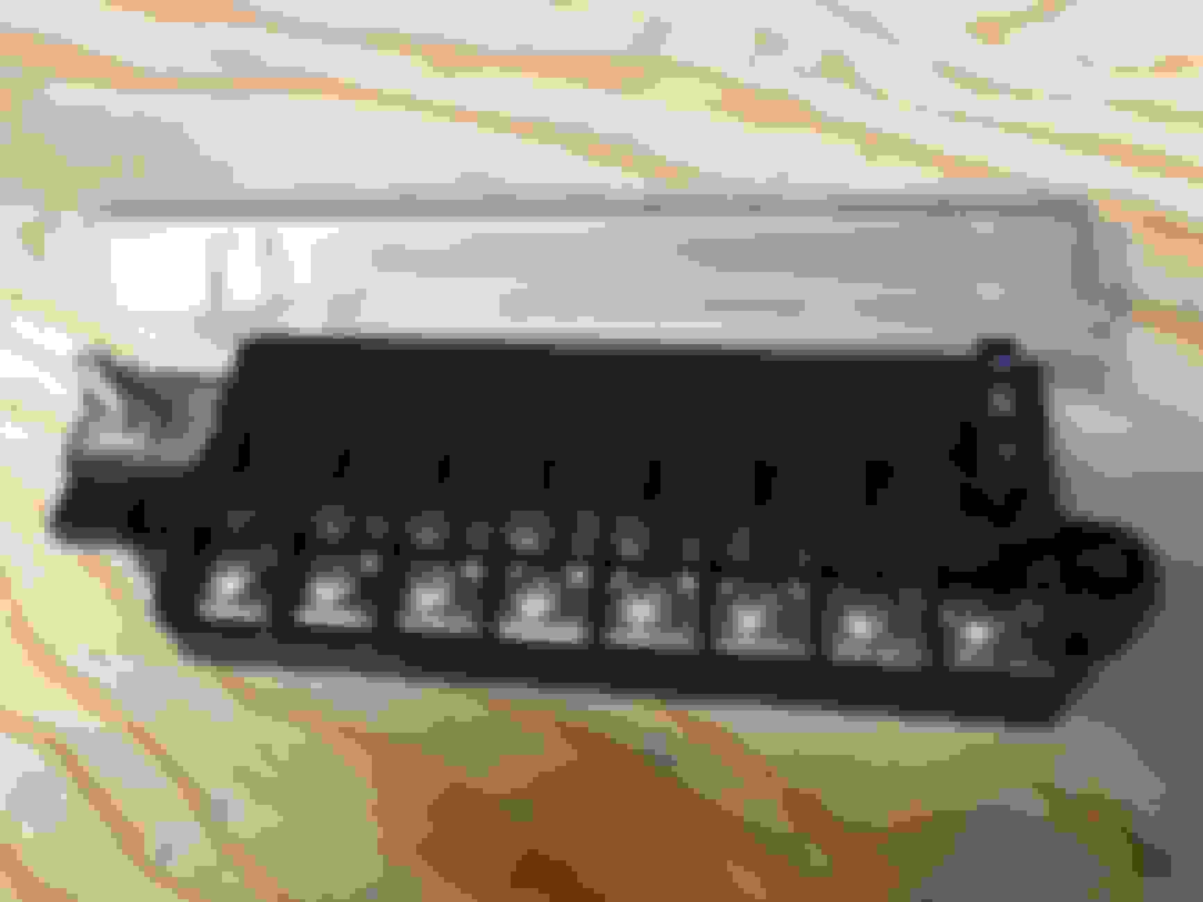
I loaded up in some weather proof crimp connectors and a new tool. I got the connectors from Amazon. I fell in love with these style of connectors some years ago - they're awesome.. Hopefully these ones aren't POS. I went ahead and loaded up on 16 and 12 AWG wire for when I get to electrical. I also invested in an 8 circuit fuse block with a common power source. This will allow me to easily add some new circuits to the car.
I also went ahead and purchased my cooling fans. I went with the SPAL fans as recommended by Freeskier. They are on;y 7.5" fans and are the largest fans I can fit from SPAL. Summit had a few 8" fan option that were rated at about the same airflow, but figured the SPAL were guarantied to produce what they stated they would push. Not thrilled about the limited space to mount fans. I hope I can keep the engine cool enough with these guys. I also bought a fan controller from Derale. I chose this one because it's rated for two fans, its adjustable, its temp sensor fits my t-stat housing and it has an auxiliary power up circuit so I can run a manual power switch.
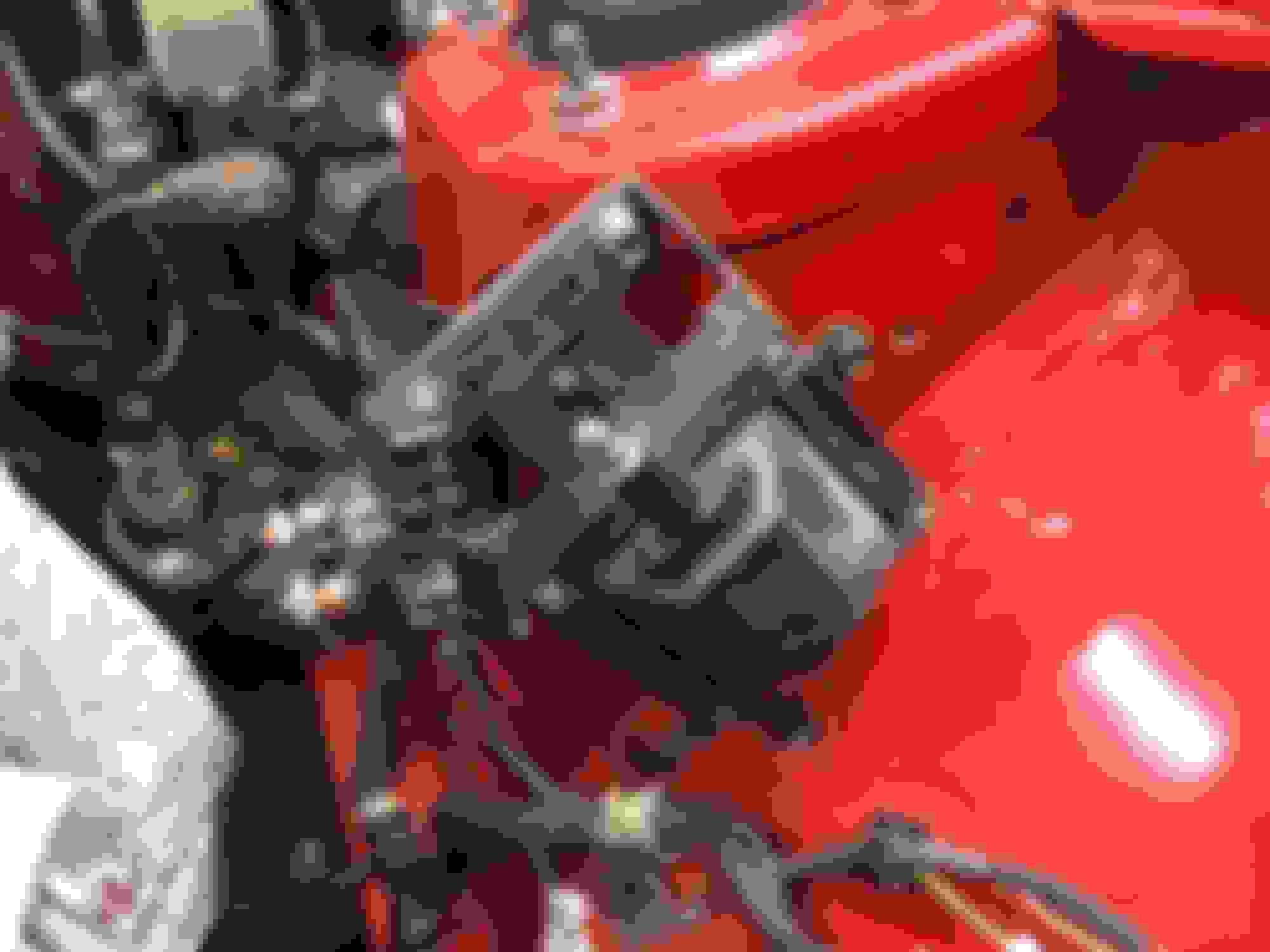
I only accomplished a few things. I've been placing some focus on locating all the accessory bits that need to fins a home in the engine bay, such as coil, starter solenoid, charcoal canister to name a few. I've made some brackets and mocked up the coil, solenoid and fuse block. I'm currently cleaning and painting all the brackets that I've made for these along with the fuel system tube brackets.
Coil and Solenoid
Fuse Block
I work tomorrow and then I'm off for two weeks. I hope to make some good progress while I'm off. I'll keep you all posted.
Nice work, but I would build some sort of shroud for the fans to maximize their efficiency.
I will definitely have to do something. The fans will be sitting directly on the radiator core. I am plan on sealing up the front section of the car to direct all the air into the radiator core, maybe using gator board or something or that nature. If it still has some troubles I might even punch a couple of louvers in the hood to create a good pressure difference between the entry/exit of the radiator. Thanks for steering me towards the SPAL fans, I might have cut a corner here without the good advice.
So I have reached a point in this build where I am so determined to have the vehicle drive and anything that is not essential to driving, reliability or SMOG is to be dealt with in a swift manor. Whether that be with a hammer, cutting device or scrapping it. I started the week off with a list of objectives and about every task on this list his fought me.
I'll start with what did go smooth. I pulled all the fuel lines back off, flushed all the lines and reassembled. And for the first time in 25 months, my car has a fuel tank in it. I can also say the fuel system plumbing is complete!
After getting the fuel system squared up I switched my focus to the heater hose lines. The 5.0 has a conjoined set of pipe that directs the heater hose lines to the rear of the engine. This pipe also includes provisions for mounting the EFI coolant sensor and a barbed fitting for the t-body coolant hose. This pipe terminates at the rear of the engine and sits less than an inch from the Mazda heater core pipes. There was no way I was going to be able to connect the Mazda and Ford parts together in less than an inch. So I went ahead and trimmed the pipe off about an inch so to make more room. The two Ford pipes are different sizes - 5/8" and 3/4". The Mazda pipes are both about 5/8". Trying to connect a larger hose to the smaller pipe would never seal. So I was forced to try and fit a smaller hose onto the bigger pipe. Once I got the hose on (no easy task), I found that the hoses had zero slack and the stretched hose would almost certainly fail in a short time.
So reliability takes precedence in this build over comfort and convenience - so I said screw it, who needs a heater in California. So I made the decision to bypass the heater core. I found a u-shaped hose that was 3/4 on one end and 5/8 on the other, and installed it to the Ford coolant pipe; however, the hose contacted the pipes on the car. So they had to go as well. So I got crazy with it and pulled the dash and removed the two pipes for the heater core. The bypass hose doesn't look great, but it will work for now and I'll save all the parts and perhaps make changes in the future to restore the heater or make it look better at least. Like I was saying - I am determined to get this think driving.
Removing the dash will also make the electrical work a lot easier. Dash was very easy to remove.
I'll have to get some photos of the bypass hose.
I then moved back to finishing installing the headers. If we go back in time a couple of months ago I mentioned that the headers would needs some working to clear the steering box. So out came the hammer. After modifying the #6 tube I also realized #5 tube would need some work, as well as the firewall to accommodate the exhaust collector/flange. So hammering away I did. Like I said - determined. I still have to finishing bolting them on, but I have made them fit. The #5 and 6 tubes clear the steering box by about 1/4", maybe less. I hope it doesn't burn up my steering box. Just as note - I did reconsider the OE manifold/headers. They will clear the box with closer to an inch, but the too would hit the firewall at the collector flange. And they look like poop, so I'll stick with the headers.
I've currently left off with the drive belt pulleys and accessories. Last weekend CJ Pony Parts was having a clearance sale and I saw a SMOG pump on clearance. This pump is usually about $225 but I bought it for $145 with shipping. So my alt., smog pump, w/p and crnk. pulleys are all torqued down. All I need to do now is mount the tensioner and bracket and find a belt.
So I'm getting closer. I am continued to be amazed how Granny's website makes it sound like everything just fits in and bolts together because it hasn't in my car. I will make it all work, but this is definitely a bit of rat rod build.
Grannys site is very misleading unfortunately. You should be ok with headers that close. You did one better than me on the heater core, I just bashed my tubes for clearance since I dont run heat either
Happy New Year�s all! It�s off to a busy start but I�m getting some things done.
I left off with installing the engine accessories and the AC/PS delete. I have that all squared away but unfortunately the belt that was recommended by Mach is too short and I need to call them and see if they have a different belt number to try.
AC/PS Delete
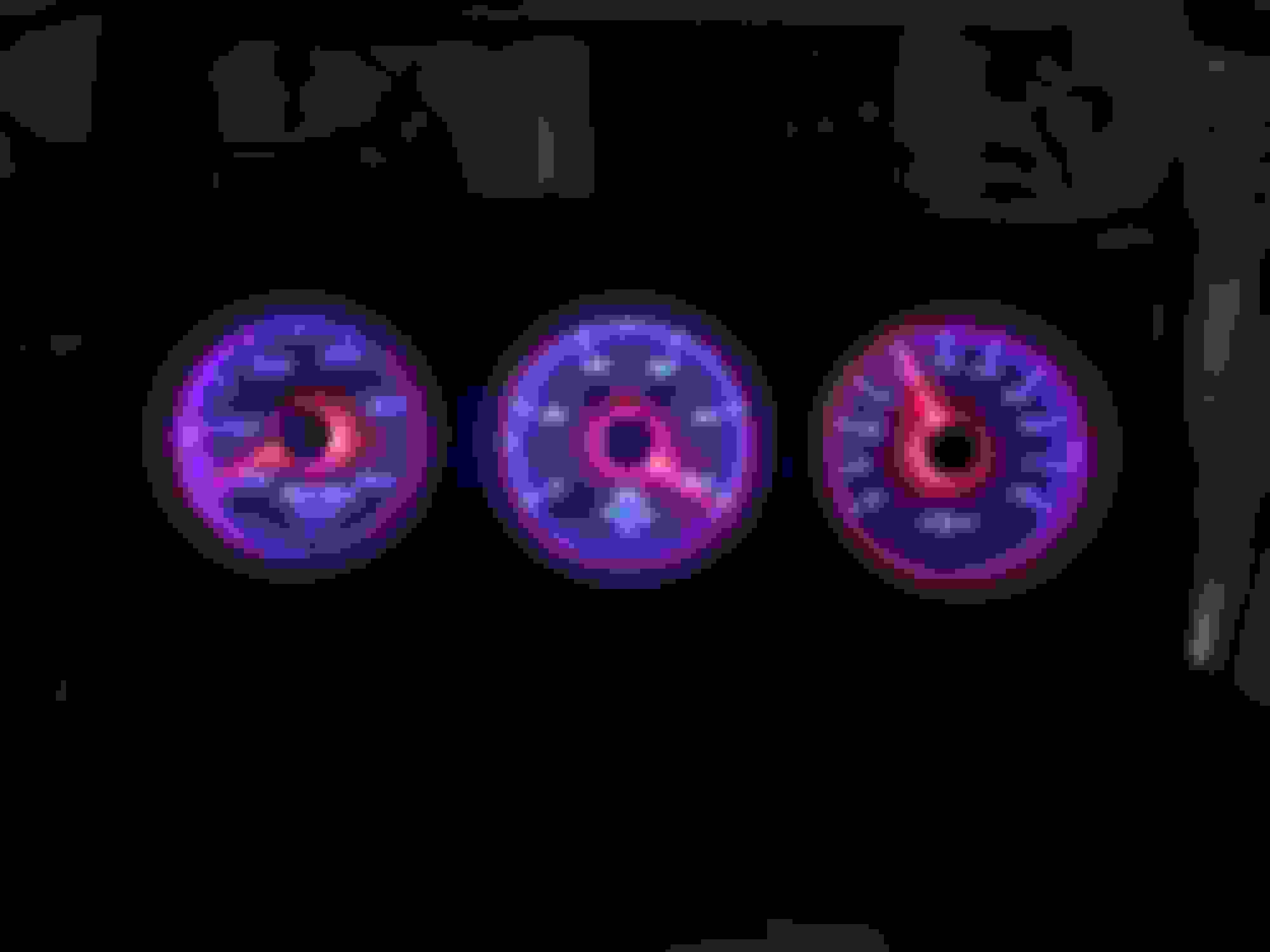
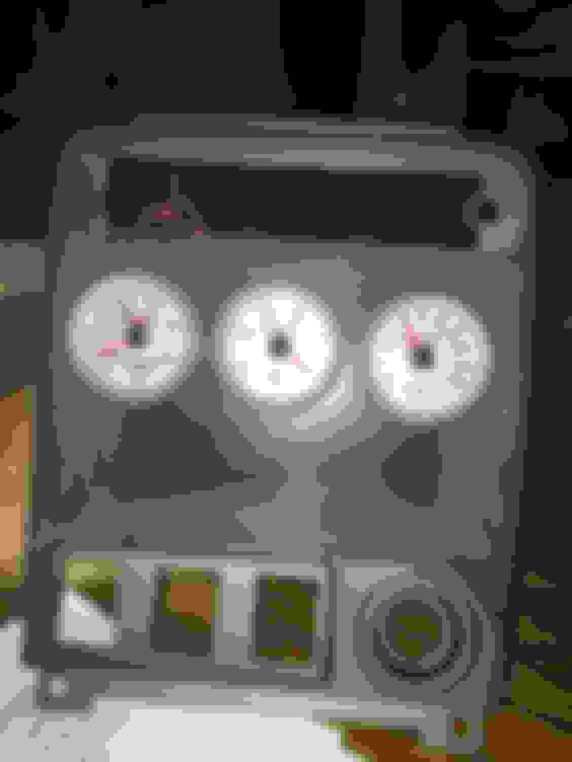
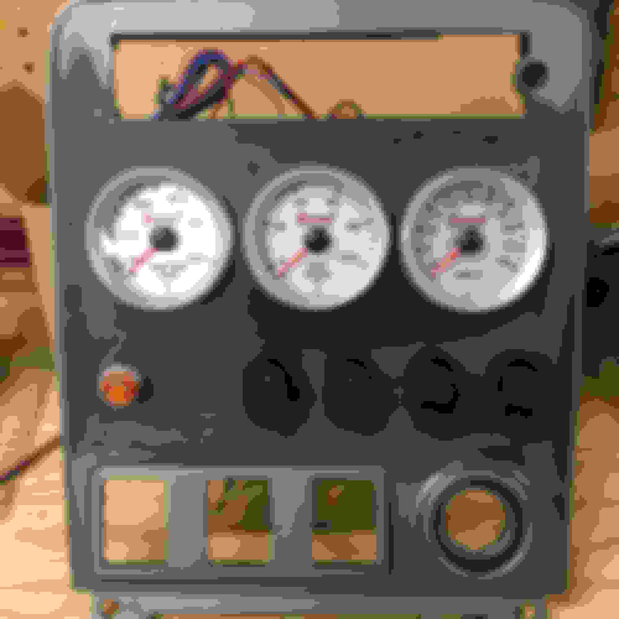
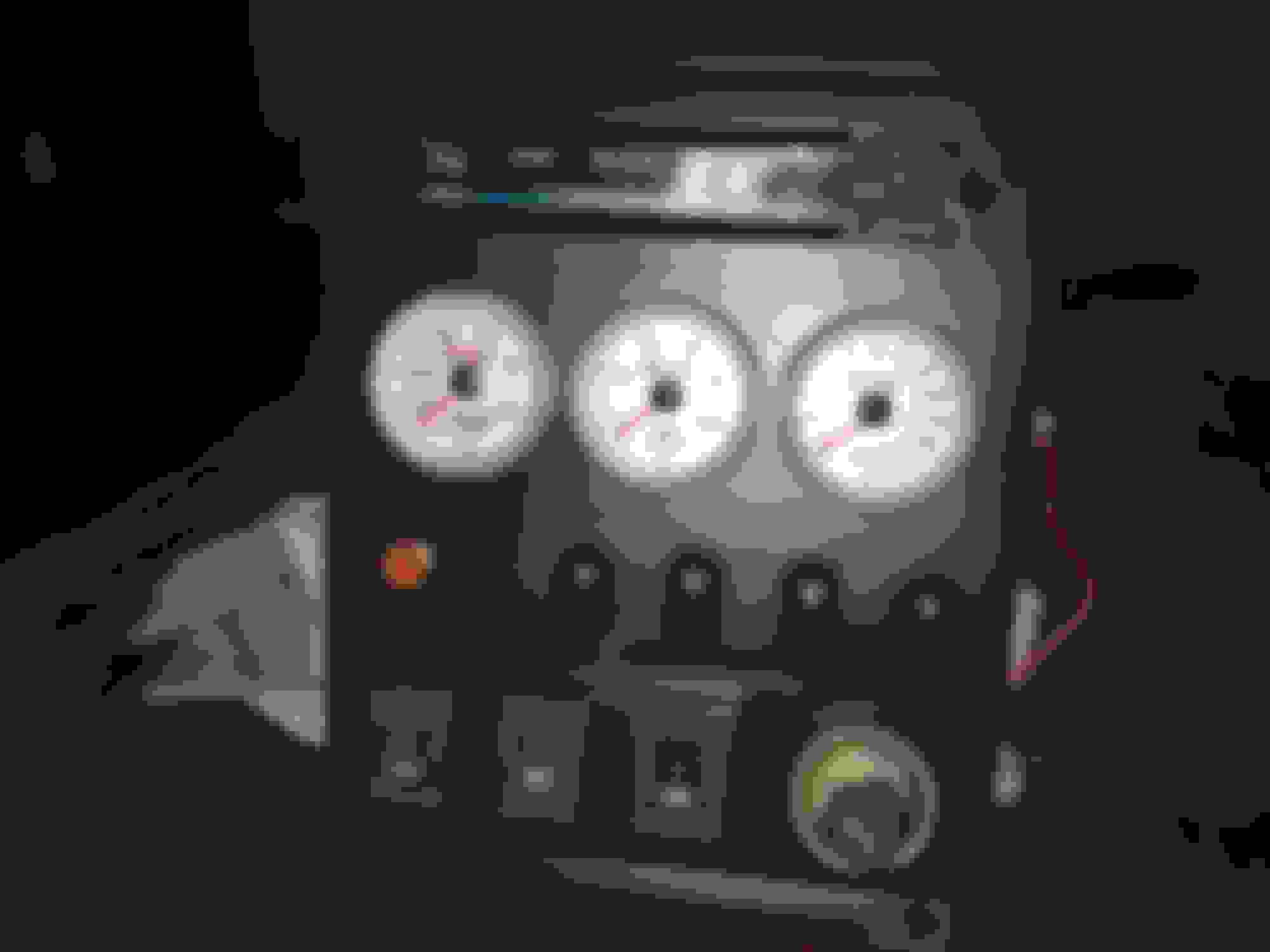
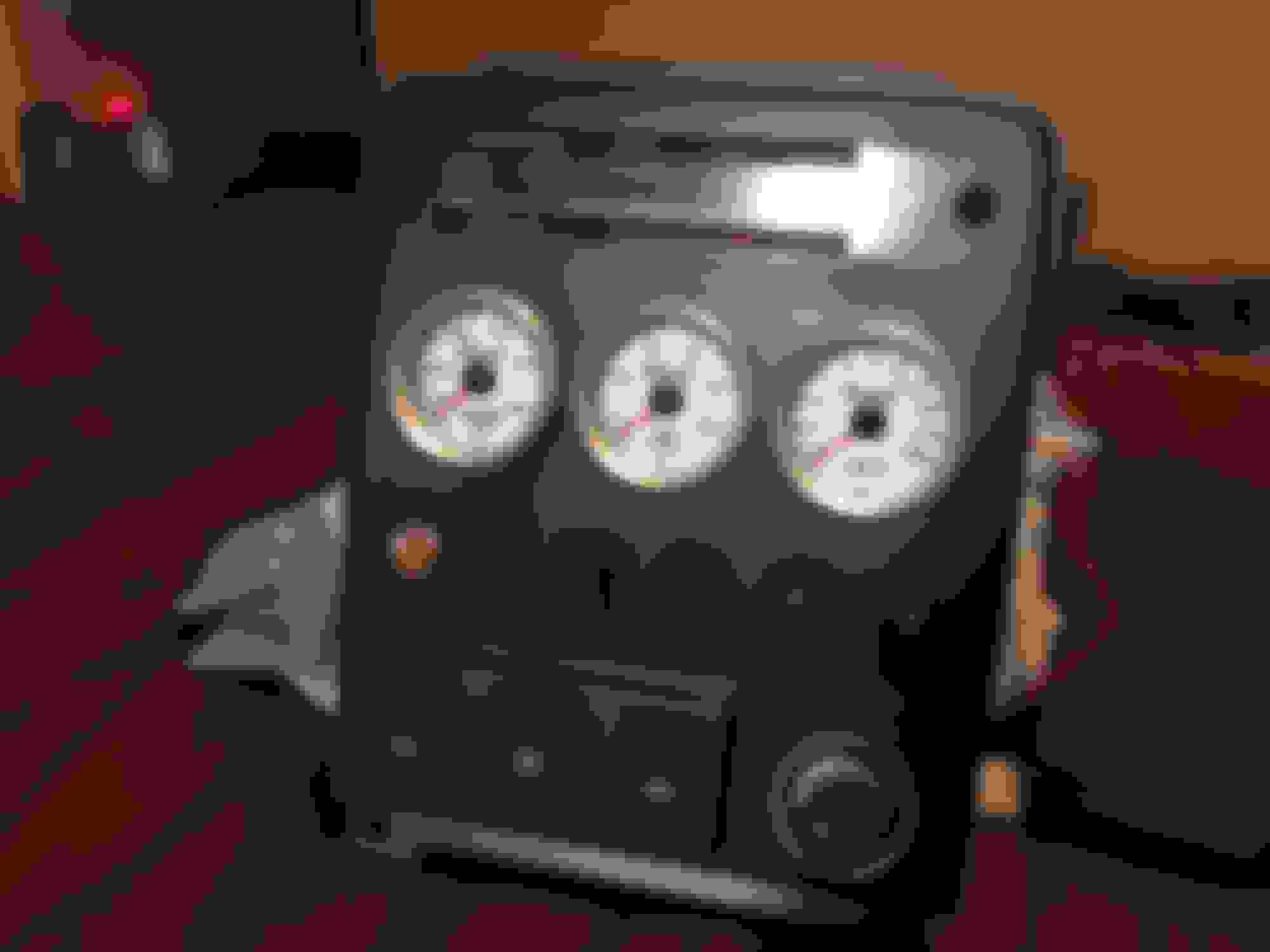
I started thinking it�s a poor idea to trust the 38 year old Mazda dummy gauges and lights, especially on a fresh engine build. So I purchased a set of Summit analog-electric gauges. They look pretty good and were a good value. I plan on mounting them in the center stack area. I am currently modifying the panel and will share some photos when I�m done.
This past weekend I dove into the wiring. I started by laying the Ford harness in the engine bay and punched a hole in the bulkhead. I accomplished this by drilling two 1 �� holes and then cutting out the material between them. I still have to paint and rivet the Mustang plate to the RX7 but at least I can start wiring the car.
I moved on to removing the Mazda harness from car. I stripped all the conduit tubing and tape form it so I could cut out the unnecessary wires. I removed all the relay connectors, Choke switch and 12A ECM connectors. I then temporality zip tied and taped the harness enough to set back in the car. I will do all the modifications and then pull it back and wrap it back up all nice later.
Mazda harness stripped. The discarded wiring.
When I was doing the Mazda harness modifications I noticed two things.
The black/white IG B+ wire Granny�s tell you to connect the Ford power circuits to is a much thinner diameter wire than the Ford wire you splice it to.
The main white/red wire going from the 1.25F fusible link to the ignition switch and fuse block is a funny circuit. It�s hard to imagine the stock alternator doesn�t burn up a 1.25F (45A) fusible link. I guess Mazda calculated the alternator would never push enough current to the battery.
To tackle the black/white wire I am going to install some relays. I will use the Mazda circuits to power the relays and run the current for the Ford circuits through a new 16awg wire.
The white/red wire is more complicated. I will run the Ford alternator strait to the battery or solenoid like the Mustang. So no need to worry about the 1.25A fusible link. The challenge however is this. The white/red wire is too short to reach the new fuse block I put in under the hood. The other is when playing around with the wire I snapped it off the buss bar for the interior fuse block � OOPS. So I am still trying to determine how to overcome this obstacle without replacing the whole fuse block. I�m open to suggestions if anyone else has deleted this main white/red wire.That�s all I have for now ��till next time.
I would check to see what is not operational now that the white/red wire is snapped off. You could also splice into the wire somewhere else to get power to it. I ran my alternator and starter to a junction post that goes to my battery in the storage bin.
I would check to see what is not operational now that the white/red wire is snapped off. You could also splice into the wire somewhere else to get power to it. I ran my alternator and starter to a junction post that goes to my battery in the storage bin.
I ended up not going for the trunk mounted battery at this time. I will go back in the future and do this. I thought in the interest of getting the car running, it would be easier to keep in under the hood for now.
Work continues to move on little-by-little every weekend. Over the last couple of weeks I have continued to tackle the wiring. I�ve added a few circuits to the car and realized I�ve nearly filled up the 8 circuit fuse block. The added circuits are for the radiator fan and the two relays (for the Ford distributor and HEGO). The wiring will keep me busy for a few more weeks. There�s still plenty of wiring left to go.
Added relay for IG system. Fan Controller
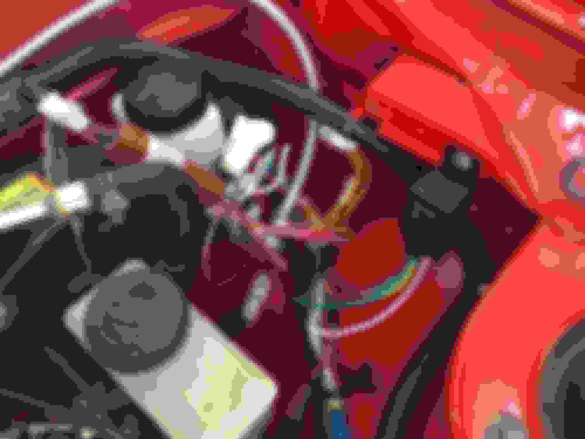
I�ve resolved the concern with the main white/red power wire. I trimmed the alternator wire at the three way splice below the master cylinder. And then added it to the end of the wire to give me the length I need to reach the under hood fuse block.
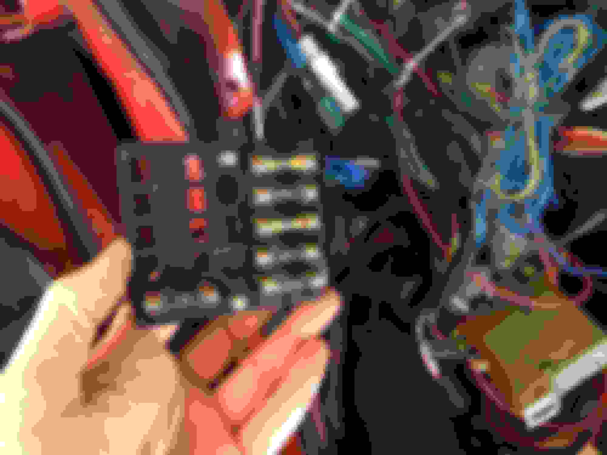
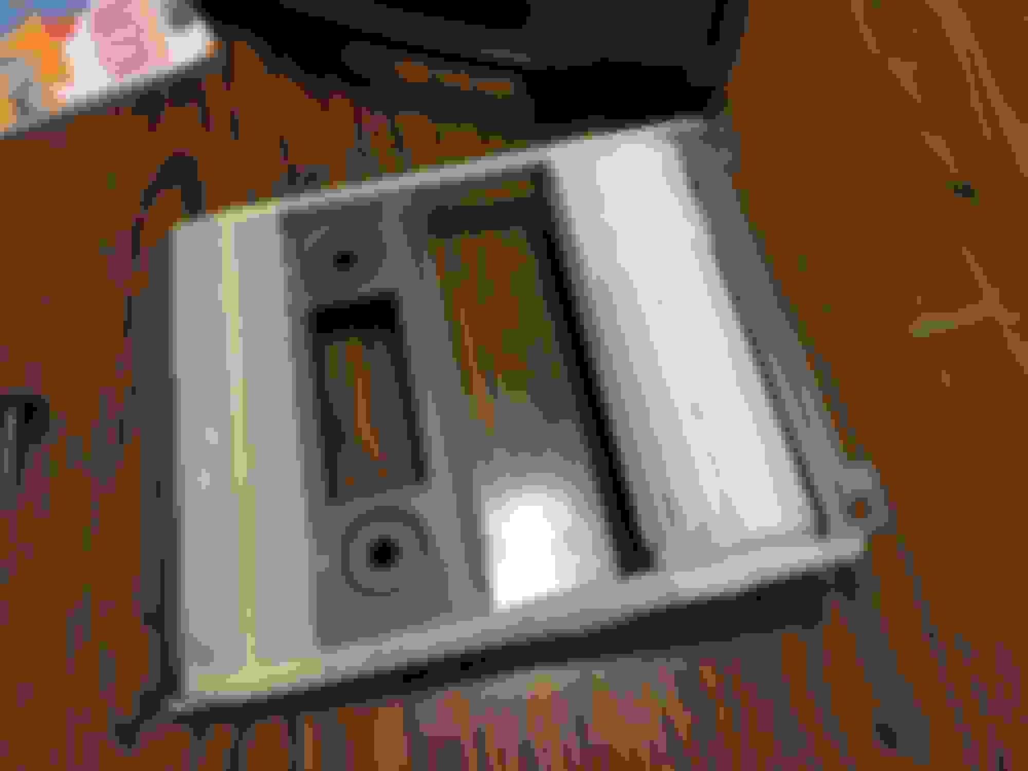
As for the broken terminal at the dash fuse box. I went to the junk yard last weekend to take some parts off of another car. There I learned that FBs have blade type fuses rather than the old fashion tube type. I thought it would be cool to just replace the whole box with something a little more modern. But once I got it home, I realized the box doesn�t fit the location (FB box bigger than the SA fuse box). And it would also create a lot of extra work to use it. So I scrapped that idea and bought another Blue Seas 4 circuit fuse block off amazon.
I mounted the new block where the speaker used to be in the left kick panel. From here it was easy to mount and wire in place. The four original circuits only needed to be trimmed and add and � eye terminal to them. Most of my time doing this was spent on making a metal mounting plate.
Battery circuits for dash fuse block gutted. Blue Sea fuse block.
My priority is now shifting to getting the exhaust done. I originally thought I would wait to do the exhaust last, but I have now changed my mind. I want to do it now so that I can make sure the transmission wiring is all out of the way and when I�m ready to crank the engine over I don�t have anything holding me back.
Before I spend any money on the exhaust I need to speak to a Smog Referee. Smog refs in CA are the ones who approve engine swaps (among other things) for vehicles to be emissions street legal. After I confirm with them a few things, I will buy a converter and a muffler and probably bring the car to an exhaust shop. I don�t have a welder or a good spot to fabricate one myself, so I figure this would be money well spent.
Anyone have any suggestions on a muffler? I plan on doing a y-pipe and single exit exhaust following the stock exhaust path. Maybe a Flow Master for that classic SBF sound?
Last weekend at Pick-n-Pull I also scored a set of rear calipers for the 12A-LSD diff. I should now have everything I need now to swap the rear axle out.
I have this muffler https://www.summitracing.com/parts/JEX-MF1229 Its a copy of a magnaflow, and sounds awesome. I also did 2.5" dual from the headers to a y pipe with 3" over the axle. I can take a picture of the exhaust if you want, but a muffler shop should be able to figure it out
I have this muffler https://www.summitracing.com/parts/JEX-MF1229 Its a copy of a magnaflow, and sounds awesome. I also did 2.5" dual from the headers to a y pipe with 3" over the axle. I can take a picture of the exhaust if you want, but a muffler shop should be able to figure it out
Thanks for the recommendation. I like the price and I bet it sounds good.
If you have pictures that would be awesome. Especially of the y-pipe area. Are you running a cat? If so, where does the driver side exhaust pipe crossover to the right side? I�m thinking of doing doming similar to the Camaros and having it crossover just behind and below the bell housing.
I do not have a cat i have the exhaust pipe crossover under the tailshaft area to gain more ground clearance.
Hey all. I haven't really done much the last few weeks. Wife has me taking care of some projects around the house.
This week I did stop and speak with the smog referee. He unfortunately didn't have good news for me. I was planning to do an exhaust setup as described on Granny's page but he's not okay with that. He is insistent on keeping the four catalytic converters. I really don't want to run cats under my feet or along the left side of the car. I spent a little time looking for complete CA legal h-pipes and so far only see one from Mangnaflow for about a grand - ouch. I will continue to explore and see what I can come up with. I might also stop and speak with a different smog referee and see if I can get them to read how the Granny testimonial did it. After all, it should either be okay, or someone passed a car that should have not have. I might also try and track that guy down who did the testimonial.
I hate technicalities. As long as all the devices are working and the tailpipe is clean why should they care.
great work, i am trying to figure my exhaust out as well, fortunately i do not live in CA and registering it as an antique, no safety or emissions needed!
i am concerned about getting the exhaust past my trans mount with dual pipes, but it just snowed another 10 inches this week so i wont be rolling it out side to put on the lift until spring
Here is the little side project I have been working on. I still have to wire it all up, but you get the idea. I only have plans for one if the rockers switches thus far, but I figured better to install now because I will think of something I want to add later I�m sure. Before I started cutting out the center. Glued in a piece of .250� styrene and filled the gaps with some CA adhesive. Testing the gauges out. Test fitting the gauges. Gauges, rocker switches and MIL Finished product