
water injection... optimizing jet location

Thread Starter


Joined: Oct 2001
Posts: 6,279
Likes: 728
From: Florence, Alabama
water injection... optimizing jet location
bill shurvington suggested possibly locating the water injection jets in the bosses on the rotor housing normally reserved for the oil injectors.
i have never liked the typical 3rd gen WI jet/s location in the elbow. i feel it may result in uneven distribution. further, my interest is in getting the kick in the combustion chamber so the closer to it the better. i was planning on locating a jet in each of the runners in the lower intake manifold... but perhaps the oil injection holes might be better.
perhaps arguing against the location might be that the water gets into the combustion cycle a bit late...
i would appreciate any comments.
thanks,
howard coleman

Rotary Enthusiast
Joined: Feb 2001
Posts: 1,094
Likes: 0
From: Orange County, CA
I've seen the mist that gets generated by some of the WI kits and the water seems like it's highly atomized, so I think that at or before the elbow is better because the air space is larger and would get distributed better in the air moving by.
I like the idea of the jets on the LIM but it seems like it would be a lot of work.
As for the oil injector holes, I don't think you would get the water distributed evenly there. You would need to enlarge the hole, and the injector would have to be close to the chamber to get a good mist. But I think it would just squirt in, due to the pressure it has to contend with from the air rushing in from the turbo.
I think the better solution would be to modify or make better water injectors.
What I plan on doing is getting one of the Greddy elbows with the two injector mounts and modifying those. That would be the best of everything, as the injectors would fire with the flow of air, and the injectors would not obstruct airflow.
Injecting further upstream gives a benefit of charge cooling and you still have droplets entering the engine to keep those hot spots under control. It's alot easier to implement as well. Distribution may not be perfect but I would suggest injecting as far upstream as possible for charge cooling as it allows the droplets to really atomize and mix to make the droplets very tiny as they enter the combustion chanber. Too close and the droplets may never get a chance to atomize resulting in pooling or excessively large droplets entering the combustion chamber. just my opinion.
Originally Posted by howard coleman
i have never liked the typical 3rd gen WI jet/s location in the elbow. i feel it may result in uneven distribution. howard coleman
From my understanding placing the injector in the elbow further helps cool the intake charge(which can be seen with your air temp sensor). I custom designed my 2 stage WI set-up and mine is located in the elbow. I designed my nozzle to protrude 1/2 way into the intake path at the elbow with a 90 degree fitting so the nozzle faces into the air path and away from the throttle body. I did this as to enhance the optimization of the water. Think of it as spraying water with your garden hose into a stiff wind and the water fanning out and coming back at you in millions of tiny droplets. This enhances the cooling effect. The only down side to this is that you will lose about .5 psi having the water blowing directly against the intake charge.
To add, I have my shurflo pump connected to a shurflo accumulator. This keeps my WI system under full time 100psi with hard lines. I like it this way because when my solenoids activate, the water is immediately being forced through strictly under the pressure from the accumulator so my pump doesn't always have to activate. This allows my pump to last longer and is also cheap insurance for my engine if the pump fails(at least I will still have pressure under boost). I also installed some LED's in my car so I can see when the pump kicks on and off and for both solenoid valves.
Last edited by t-von; Jan 9, 2006 at 10:57 PM.
7 Rx-7s since 1980
Joined: Mar 2004
Posts: 438
Likes: 1
From: oHIo
Originally Posted by howard coleman
bill shurvington suggested possibly locating the water injection jets in the bosses on the rotor housing normally reserved for the oil injectors.
i have never liked the typical 3rd gen WI jet/s location in the elbow. i feel it may result in uneven distribution. further, my interest is in getting the kick in the combustion chamber so the closer to it the better. i was planning on locating a jet in each of the runners in the lower intake manifold... but perhaps the oil injection holes might be better.
perhaps arguing against the location might be that the water gets into the combustion cycle a bit late...
i would appreciate any comments.
thanks,
howard coleman
i have never liked the typical 3rd gen WI jet/s location in the elbow. i feel it may result in uneven distribution. further, my interest is in getting the kick in the combustion chamber so the closer to it the better. i was planning on locating a jet in each of the runners in the lower intake manifold... but perhaps the oil injection holes might be better.
perhaps arguing against the location might be that the water gets into the combustion cycle a bit late...
i would appreciate any comments.
thanks,
howard coleman
That late in the air-flow...you're not talking about just water are you?
Tony
Thread Starter
Joined: Oct 2001
Posts: 6,279
Likes: 728
From: Florence, Alabama
thanks for the helpful comments...
upon further consideration i probably will pass on the oil injection port idea. just like fuel injectors have to have rising pressure to balance against boost to maintain constant flow water injection needs to contend w pressure in the manifold. while i haven't checked one of my rotor housings my guess is that the oil injection boss is located at a point where compression is starting to effect the combustion chamber-pressure. that could create a significant hurdle for the, say a measley 100 psi, water injector. probably poor atomization. (as Atilla posted).
rightly or wrongly my primary emphasis on my system will be to emphasize using the cooling for the chamber, not the air from the IC thru the throttle body. my jets will locate in each of the 4 runners and i will make a small log manifold to keep things tidy.
t-von, i really like the accumulator and hard lines. in addition, i believe the accumulator frees you up to locate components without regard for gravity.
Tony, i plan to run a modest amount 15/85 of alcohol to water to decrease water surface tension and thereby lower the droplet size.
currently i am near 88% maxxed out on my 850/1600 injectors at 14 psi boost. i do plan to tune for WI so i will ultimately be running around 13 to 1 afr and my injector duty cycle will back down into the 70% range. i will run a bunch of safeguards in the system that will kill my ignition. forget LEDs, when they come on it means your engine is toast.
currently i am planning to run the new Coolingmist variable pressure regulator to stage the boost. i liked the alternative 2 stage full-blast-on-the-pump concept, but since i am going to run a jet in each runner it would have resulted in 8 jets which even for me would have been way over the top.
if i might shift gears...
where have you located components?
howard coleman
Trending Topics
REW'd FB
Joined: Dec 2004
Posts: 2,685
Likes: 1
From: WA
I just picked up a cooling mist kit. And I am very interested in this thread. Howard you mentioned that you want to plub the injectors into the LIM. I have not held a Groundzero manifold in my hand but I wonder if this might be a solution. Just something to think about.
Z
Z
Banned. I got OWNED!!!
Joined: Dec 2002
Posts: 4,192
Likes: 0
From: wishing i was back in FL
Originally Posted by twokrx7
Injecting further upstream gives a benefit of charge cooling and you still have droplets entering the engine to keep those hot spots under control. It's alot easier to implement as well. Distribution may not be perfect but I would suggest injecting as far upstream as possible for charge cooling as it allows the droplets to really atomize and mix to make the droplets very tiny as they enter the combustion chanber. Too close and the droplets may never get a chance to atomize resulting in pooling or excessively large droplets entering the combustion chamber. just my opinion.
 the guys here that run them always put it right after the intercooler. this way it atomizes very well and works beautifully. 30psi/ pump gas anyone? ahahahaha EGT's staying around 700 degrees celcius. ohhhhh yeaaaaaa
 Senior Member
Joined: Oct 2002
Posts: 685
Likes: 1
From: Portland, OR
I would tend to think that injecting as soon as possible after the IC would do the most heat removal. It will have more time to disperse evenly in the charge.
Another thing to consider is your AIT sensor location. I found on my wi setup that the water made the sensor read very wrong values. I had to move the AIT sensor upstream of the wi.
Justin
Another thing to consider is your AIT sensor location. I found on my wi setup that the water made the sensor read very wrong values. I had to move the AIT sensor upstream of the wi.
Justin
Rotary Enthusiast
Joined: Feb 2001
Posts: 1,094
Likes: 0
From: Orange County, CA
Originally Posted by z-beater
I just picked up a cooling mist kit. And I am very interested in this thread. Howard you mentioned that you want to plub the injectors into the LIM. I have not held a Groundzero manifold in my hand but I wonder if this might be a solution. Just something to think about.
Z
Z
The only thing that would concern me is that comes in right before the fuel injectors; don't know if it would affect the spray pattern of the injectors.
A third option is making a injector block that fits between the UIM and LIM, similar to those that add more injectors, and plumb them in all four holes. I think it raises the UIM by about 3/4 inch.

Rotary Freak
Joined: Apr 2003
Posts: 2,702
Likes: 1
From: DC Area
I have the dual stage dual nozzle kit from them. Its not instaled yet but I had planned to put one right after the intercooler and one about mid way between the tb and intercooler. I got the angled injectors option but I do like Howards idea to place them in pointing backards against the flow. Would there be any benefit to placing one on the turbo side of the intercooler instead.
development
Joined: Aug 2002
Posts: 5,714
Likes: 7
From: Lafayette, LA
My suggestion(s)...if you plan to tune for water, you might want to think about HSV (high speed valves) for the water injectors. I think aquamist is one of the only companies that make a valve that can keep up with a fuel injector. This will allow you to mirror a fuel injector and inject an accurate % of water to fuel...which is ideal for tuning (not happy with EGT's? up the % of water by changing only the nozzles)
IMO, two stage (dummy) full-On OR full-Off systems are a waste of money and space.
I also think 4 water injectors isn't necessary (and will get pricey with HSV's). If you want to add water after the TB, add only in the secondary runners, it will be just as even distribution...and sorta give those 1600cc injectors a higher octane fuel feeling, if you know what I mean.
as far as components, here is my shurflo and accum. tank. No LED needed for the pump, you can here this baby when she's on. Only runs for about 2-3s every once in awhile.
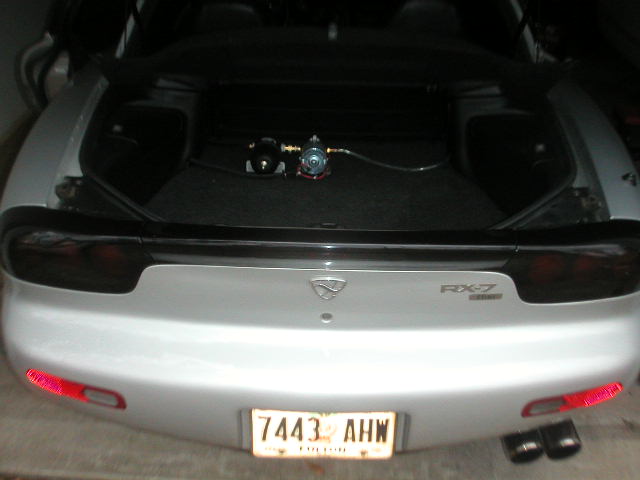
I look forward to hearing more about your twin project and best of luck with your 13:1 A:F tuning goal!
IMO, two stage (dummy) full-On OR full-Off systems are a waste of money and space.
I also think 4 water injectors isn't necessary (and will get pricey with HSV's). If you want to add water after the TB, add only in the secondary runners, it will be just as even distribution...and sorta give those 1600cc injectors a higher octane fuel feeling, if you know what I mean.
as far as components, here is my shurflo and accum. tank. No LED needed for the pump, you can here this baby when she's on. Only runs for about 2-3s every once in awhile.
I look forward to hearing more about your twin project and best of luck with your 13:1 A:F tuning goal!
Thread Starter
Joined: Oct 2001
Posts: 6,279
Likes: 728
From: Florence, Alabama
i think too much cooling is lost when injecting upstream. part of the cooling effect is absorbed by the significant mass of the UIM and LIM. both are aluminum which absorbs heat like a magnet.
i would rather cool the combustion rather than the manifolding.
i also wish to minimize washing the inner manifold w dropout due to all the direction changes of an upstream injected flow... water being a whole lot heavier than air.
as far as nozzle direction, most of what i read suggests you spray at a 90 degree angle to airflow. i recognize that much of this is conjectural and i do see the merits of spraying in a 180 degree direction for dispersal.
howard coleman
Thread Starter
Joined: Oct 2001
Posts: 6,279
Likes: 728
From: Florence, Alabama
dubulup,
thanks for the picture. an accumulator will be part of my system.
you raise some interesting points.
while boost remains constant, say from 4000 to 8500, fuel does not. i would rather key my WI off fuel usage rather than boost. fuel usage often declines 20% after peak torque. ideally WI should follow. the problem as i understand it w the Aquamist controller is that it either keys off your primary or secondary injector. (you wire it to one or the other). if i could find a signal within my PFC for injector duty cycle and could key it into the AQ controller than i would be really happy. i have looked at it and haven't found it... anyone out there figure it out? maybe wire it to both?????
the second best option as i see it is the new Coolingmist variable controller. all the good adj on the way to peak torque but no way to reduce after...
as to 4 injectors...
i consider the primary part of the intake system to be much more important than most. consequently my primary ports have been highly massaged. i think that mazda spent alot of time shaping/positioning the primaries so they would create turbulance as they mix w the secondary intake in the combustion chamber. i want my water vapor to be a part of the mix. i will not be using HSVs (though i will probably use AQ jets) so the cost is inconsequential.
Dubulup, where is your tank? what lines are you using, aeroquip? stainless steel?
howard coleman
Last edited by Howard Coleman; Jan 10, 2006 at 12:25 PM.
My water injection nozzle was in the IC outlet tank wall directly opposite of the IC outlet pipe, Aquamist pump was mounted to the bottom flank of the driver's frame rail about even with the oil pan flange, and used a simple pressure switch to turn on. I ran around 20-25% water:fuel on the low end, around 10% at peak torque, and then a bit higher above peak torque. If I were to run >15 psi boost again and decide to go with WI (fwiw, I would not do WI again unless I was endurance racing) I would use an aquamist system pump/accumulator/controller/solenoids/nozzles) and run the controller off the secondary injector signal all triggered to engage at around 15 psi boost. Limiting factor of the Aquamist is flow rate of the pump. If you are producing some big horsepower you need multiple pumps to keep the WI ratio above 10%.
development
Joined: Aug 2002
Posts: 5,714
Likes: 7
From: Lafayette, LA
Originally Posted by howard coleman
the problem as i understand it w the Aquamist controller is that it either keys off your primary or secondary injector. (you wire it to one or the other). if i could find a signal within my PFC for injector duty cycle and could key it into the AQ controller than i would be really happy. i have looked at it and haven't found it...
anyone out there figure it out? maybe wire it to both?????
anyone out there figure it out? maybe wire it to both?????
after the transistion to all four injectors, the injection (ms) time drops due to both injectors firing at the same time. i.e. instead of an 850cc injector suppling fuel (to one rotor), you now have a 2450cc injector.
mapping off any injector will yield the same duty cycle.
of course best results would be to map each nozzle on the respected rotor.
****this is how Haltech works...if someone has conclusive evidence the PFC varies injector duty cycle for each injector please correct me.
I guess the easiest test is to look at a data log and notice the duty cycle before the injector transistion and after.
Howard, if you haven't been there yet, you may want to check this water injection board:
http://www.waterinjection.info/phpBB2/
I recall at least some threads discussing pre/post turbo injection, pre/post intercooler injection, manifold injection, etc.
http://www.waterinjection.info/phpBB2/
I recall at least some threads discussing pre/post turbo injection, pre/post intercooler injection, manifold injection, etc.
Originally Posted by howard coleman
t-von, i really like the accumulator and hard lines. in addition, i believe the accumulator frees you up to locate components without regard for gravity.
Thread Starter
Joined: Oct 2001
Posts: 6,279
Likes: 728
From: Florence, Alabama
t-von
it sounds like you have a well thought out system. i am sure many of us would appreciate pictures and they would be a good add to this thread.
artowar
yes, that's one of the best links/info centers re WI on the net. i monitor and have posted on it. i recommend it to any who are looking at WI.
for those on the fence as to WI.... if you are properly tuned you are probably running 11.3 to 1 AFR and 14 degrees of IGL... w WI you can take approx 18% of the fuel out and run a proper amount of advance and drop your egts a couple hundred degrees and safely crank up the boost from 15 to 18.
but what if the WI fails?
that's where you have to spend some intellectual and monetary capital setting up failsafe mechanisms. they are all there for the taking but i wouldn't recommend you use an LED you will need to tie them in to boost or fuel/ignition cuts.
once complete, have fun running 19 psi on pump.
howard coleman
it sounds like you have a well thought out system. i am sure many of us would appreciate pictures and they would be a good add to this thread.
artowar
yes, that's one of the best links/info centers re WI on the net. i monitor and have posted on it. i recommend it to any who are looking at WI.
for those on the fence as to WI.... if you are properly tuned you are probably running 11.3 to 1 AFR and 14 degrees of IGL... w WI you can take approx 18% of the fuel out and run a proper amount of advance and drop your egts a couple hundred degrees and safely crank up the boost from 15 to 18.
but what if the WI fails?
that's where you have to spend some intellectual and monetary capital setting up failsafe mechanisms. they are all there for the taking but i wouldn't recommend you use an LED
you will need to tie them in to boost or fuel/ignition cuts.once complete, have fun running 19 psi on pump.
howard coleman
development
Joined: Aug 2002
Posts: 5,714
Likes: 7
From: Lafayette, LA
Originally Posted by howard coleman
but what if the WI fails?
that's where you have to spend some intellectual and monetary capital setting up failsafe mechanisms. they are all there for the taking but i wouldn't recommend you use an LED you will need to tie them in to boost or fuel/ignition cuts.
once complete, have fun running 19 psi on pump.
howard coleman
that's where you have to spend some intellectual and monetary capital setting up failsafe mechanisms. they are all there for the taking but i wouldn't recommend you use an LED
you will need to tie them in to boost or fuel/ignition cuts.once complete, have fun running 19 psi on pump.
howard coleman
to be 100% safe, I would want to monitor water flow in the high pressure line after the solenoid (since accumulator is holding the pressure not the pump). Once it drops below the optimum level, either cut boost control to open WG at spring level or dial it down to pre-WI levels (can't do with MBC). <--also tie into a water level sensor.
I'd love to hear your ideas
development
Joined: Aug 2002
Posts: 5,714
Likes: 7
From: Lafayette, LA
Originally Posted by mjw
Where are you guys ordering your accumulators and what is the part #?
Thanks.
Thanks.
Thread Starter
Joined: Oct 2001
Posts: 6,279
Likes: 728
From: Florence, Alabama
Coolingmist has the same item for $39.99 which is 4 dollars more. i would rather support an rx7 owner and site vendor as there are a number of items i will be buying from CM, such as the controller, and they do provide lots of help on their site and over the phone.
if i really needed the $4 i probably could talk CM out of it
howard coleman
if i really needed the $4 i probably could talk CM out of it
howard coleman