When you click on links to various merchants on this site and make a purchase, this can result in this site earning a commission. Affiliate programs and affiliations include, but are not limited to, the eBay Partner Network.
If you select "Sequential Turbo Control" box as unchecked, boost is controlled through the Precontrol output. This is the parameter "Advanced PC" . It can only be read by the Datalogit. The value is linear 0-255, with 255 being 100% duty.
If that precontrol wire has been cut, you need to control through the "wastegate" output. In order for the wastegate output to work, you need to leave sequential turbo control on and change the turbo transition values, as mentioned in the first post of this thread:
The parameter to log is Advanced WG, and it is also logged through the datalogit only. Neither the PC or WG are a switch. Switches come through as 0 or 1 bits in the Datalogit, and are viewable on the commander under the etc--> sensor/sw check.
The precontrol and wastegate outputs are fixed frequency, duty controlled (pulsewidth modulation). They rapidly cycle a pneumatic solenoid, whether it is the stock one or the BorgWarner one. The duty cycle is the ratio of ON time to OFF time, with a higher number corresponding to more ON time. The design of the solenoid and the plumbing affect what actually happens with higher duty cycle. You need to look at the duty cycle and boost (PIM) curves in order to understand what's going on.
[PAC] Port Air Control
[CCN] Charge Air Control
[TCN] Turbo Control
[PRC] Pressure Regulator Control
Port air control is in the ACV for control of secondary air injection. Port air corresponds to the airpump injecting air into the exhaust ports in order to stabilize combustion, lean out the engine-out mixture, and reduce misfire.
Charge air control is in the compressor Y pipe for sequential turbo control. Turbo control is in the exhaust manifold, also for sequential turbo control. Those two values are always inverted (they are never on at the same time; same as stock ECU). They are set according to the turbo transition high and low map. Pressure regulator control is the hot start solenoid, to raise fuel rail pressure when fuel temps are high enough.
if you are plugging it into the precontrol, you could mess around with the commander and MAYBE tune it just by guess and check. To do it in any kind of methodical way you want to look at the duty cycle curve.
If you have access to a Datalogit and can post some datalogs I can help analyze them.
There is a lot of great info here, and it seems really straightforward, but I too am having some problems.
I have my boost solenoid connected to the wastegate connector. Its a MAC 3 port.
port 2= wastegate actuator (internal wastegate)
port 3= open
port 1= boost source
it seems like the WG% is going way up well before my setpoint is hit. my actual wastegate spring pressure is about 5psi.
Thanks for any insight you might have.
also it seems like maybe newer versions of FC edit use TPS voltage instead of percent.
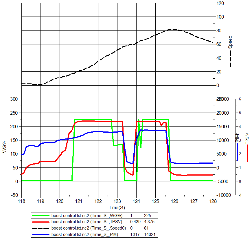
The blue line is PIM (manifold pressure). Around 122 seconds, notice how the line rises but then flattens out while the green line (wastegate duty) is still at max? That means the ECU is commanding a closed wastegate with max duty cycle (trying to bleed all the air out), but the gate is opening anyway.
Revisiting an old thread to make sure I don't blow up my FD. I read through this a few times and have a few questions
1. I am running the Apexi Solenoid that comes with an AVC-R. My AVCR got shorted out so I'm re-purposing the solenoid. @arghx 1st post said you can connect to Pin 4U for the pulse width ground and then a 12V power source, pin 1B. Does it matter which color wire of the solenoid I use for each pin or does it work regardless of which pin so long as one is 12V and one is the pulsewidth ground?
2. Plumbing. I'm running a Turbosmart Wastgate that has two ports on it. Currently, the top port is open and the bottom port is connected to a vacuum reference nipple on the UIM. I *think* I have a 3 port as I see three holes on my solenoid even though only two has barbs attached to them. Would I just connect reference to one port of the solenoid and the other port to the bottom waste gate? What about the third port (I think).... would it connect to the top port of the wastegate?
3. In my setup, would anything change in term of PFC settings? I do have a Datalogit.
Does your harness still have the precontrol solenoid connector? I'm trying to remember if the AVC-R solenoid has the same connector as the "boost control kit" solenoid. If it doesn't, you could buy the connector from Ballenger motorsports (why hardwire when you don't have to).
Try using the same plumbing you had with the AVC-R. Basically you can hook it up to the side port of the wastegate and leave the top vented, or you can hook up both ports on the gate, using the solenoid to supply pressure through the top port. Turbosmart instructions or AVC-R instructions will explain. The AVC-R solenoid is a standard 3 port solenoid, you just want to make sure you don't get the ports mixed up.
For the PFC settings you can plug into the precontrol connector and turn sequential turbo control off, and then tune boost and duty like I mentioned in the original post. The other option is to do what I mentioned in post 1 is to sort of "trick it" by plugging into the wastegate and setting the turbo transition/sequential turbo control low. I wrote that before Banzai Racing pointed out to me that you can simply plug into the precontrol and turn off sequential turbo transition.
Does your harness still have the precontrol solenoid connector? I'm trying to remember if the AVC-R solenoid has the same connector as the "boost control kit" solenoid. If it doesn't, you could buy the connector from Ballenger motorsports (why hardwire when you don't have to).
.
I don�t think so. I don�t even know where to look for this connector. I am not the first owner and given how relatively clean my engine bay is, I think the wiring for the twins is gone. Where would said connector be?
I didn�t have the AVCR working when I bought my car. It was there but the car has needed a ton of work (I think you commented on my build post) which means I have no idea how it�s suppose to be plumbed. So to my wiring question, if I have to wire it, does the color wire matter as it relates to which pin they need to be connected to?
Folllowing up to help save others some time. I got this working after fiddling with it a bit. I wired the solenoid to pin 4V (pre control) and to +12V. I tried plumbing the solenoid to the Wastegate using the 2 port method (connecting to top and bottom of WGs) and it didn’t work at all. I switched to single port method (connect to bottom port of WG, leave top open) and it worked like charm. I haven’t run a ton of tests because of the speeds needed to get a full RPM log, but I’ve noticed pretty solid results with my duty cycle between 42-50%. I consistently log boost levels higher than my boost setting in the PFC, but since it increments in steps of 5 (e.g. .50 kg/cm^2 -> .55 is the next step), it’s expected. The duty cycle does trim it up a bit but again, hard to tell without being able to really safely make repeated runs like on dyno. All in all, it’s holding boosts consistent in all the settings I’ve tried but I’m not sure I feel like its helping me spool any faster. I’m running 7psi springs and at .50 (lowest you can set), logs show a solid 8-9psi being held but I still feel like it spools a tad faster on the spring.
Folllowing up to help save others some time. I got this working after fiddling with it a bit. I wired the solenoid to pin 4V (pre control) and to +12V. I tried plumbing the solenoid to the Wastegate using the 2 port method (connecting to top and bottom of WGs) and it didn�t work at all. I switched to single port method (connect to bottom port of WG, leave top open) and it worked like charm. I haven�t run a ton of tests because of the speeds needed to get a full RPM log, but I�ve noticed pretty solid results with my duty cycle between 42-50%. I consistently log boost levels higher than my boost setting in the PFC, but since it increments in steps of 5 (e.g. .50 kg/cm^2 -> .55 is the next step), it�s expected. The duty cycle does trim it up a bit but again, hard to tell without being able to really safely make repeated runs like on dyno. All in all, it�s holding boosts consistent in all the settings I�ve tried but I�m not sure I feel like its helping me spool any faster. I�m running 7psi springs and at .50 (lowest you can set), logs show a solid 8-9psi being held but I still feel like it spools a tad faster on the spring.
you can't spool slower than direct feed to spring with conventional plumbing. The only way you could do that was if you were running a really light spring with normally open port to the top chamber on the gate and were cycling to drop rather than raise boost.
The control logic in the apexi would wind up trying to close loop that as it is back to front to what it is expecting to see.
Even after reading this I am still confused and it seems there are multiple ways of doing this. I pulled components off of my engine this past weekend and marked everything as I went. However upon reinstalling everything I was left with a hose coming off of a T fitting connecting
to the APEXI boost controller. Any idea where this is going? If it was a vent why is it so long and with a hose clamp on the end? Looked at the instructions but seems to be set up for a stock twin FD or I am reading it wrong (most likely).
Here they are, the braided and black hose. The T fitting is connected to the black hose.
Without seeing the full plumbing diagrammed out, I *suspect* that open end off the T should be connected to a pressure source so either a nipple on the upper intake manifold or off your turbo. See this link for some basics on boost control plumbing
Without seeing the full plumbing diagrammed out, I *suspect* that open end off the T should be connected to a pressure source so either a nipple on the upper intake manifold or off your turbo. See this link for some basics on boost control plumbing
I appreciate all the good info and this is a diagram of what we came up with. Maybe not that useful since most people have upgraded but this is how mine is set up using the APEXI AVC-R with boost control module.
I appreciate all the good info and this is a diagram of what we came up with. Maybe not that useful since most people have upgraded but this is how mine is set up using the APEXI AVC-R with boost control module.
so is your diagram how it�s connected now or are you asking if this is how it should be connected? You said you had one hose that wasn�t connected so if you follow the diagram, that should work.
If you have a turbo, how it�s plumbed with a solenoid is going to follow the same layout as the link I posted. The apexi solenoid and the MAC solenoid are the same.
I actually used the �simple� external waste gate method without the T in my setup.
what is your car doing? Is it over boosting? Is it only spring rate? What is your spring rate?
Sorry, that is how it is connected now. I posted in case someone needed it for reference in the future. Thanks again for the help.
Ive stumbled across an unexpected behavior of the PFC. the car is S4 w the Banzai adapter harness and the wastegate solenoid wired to pin 4V (precontrol on the S6 PFC)
It seems no matter what one puts in the field for turbo transition it always puts the WG% to 243. It does although control boost over the entire rpm range just fine with the PC%. it tries to track the boost setpoint.
Here is the dataset and log of 2 3rd gear pulls. in the first pull the target boost was set to .55 and in the 2nd pull it was set to .75 bar.
It almost makes one believe if it detects an open circuit on pin 4U it will ignore the setting for seq turbo control and alwas use 4V to control boost..


