
anyone know how to set timing on a rebuild motor ?

Thread Starter
Joined: Jun 2005
Posts: 2,753
Likes: 5
From: Seattle, Washington
anyone know how to set timing on a rebuild motor ?
anyone know how to set timing on a rebuild motor ?
I'm a do it your selfer and I have been trying to time my engine for 2+ months now.
anyone who is knowledgeable enough to set the main pulley and CAS I need to talk with you.
I'm a do it your selfer and I have been trying to time my engine for 2+ months now.
anyone who is knowledgeable enough to set the main pulley and CAS I need to talk with you.
Thread Starter
Joined: Jun 2005
Posts: 2,753
Likes: 5
From: Seattle, Washington
please, anyone who reads this thread, take a moment to think of THE absolute smartest rotary person you know direct them to me.
If your seriously interested in helping just pm me or whatever, tired of searching through hundreds of "timing" threads full of half thoughts and people promoting advice they heard from a guy who heard that from a guy who originally read the info from an import tuner magazine. Help me out with advice good enough to get this engine timed and I will pay pal you money for your time and effort. seriously want this done
If your seriously interested in helping just pm me or whatever, tired of searching through hundreds of "timing" threads full of half thoughts and people promoting advice they heard from a guy who heard that from a guy who originally read the info from an import tuner magazine. Help me out with advice good enough to get this engine timed and I will pay pal you money for your time and effort. seriously want this done


I assume this is a 2nd gen/T2 engine?
The key is... make sure the pulley and the hub that it bolts to are from the same engine. In the 2nd gen factory service manual it explains how to install it. You want to line the teeth up and drop it in. Here's a tip: with a power steering pulley unbolted it is easier to drop it in without the teeth moving out of alignment. Then you start the engine and put your timing light pickup on a leading wire. Turn the CAS to line it up with the yellow mark. If it is a stock ECU, make sure you jumper the initial set connector (see fuel and emissions section of the FSM). If it is a standalone, lock the timing at -5L -20T.
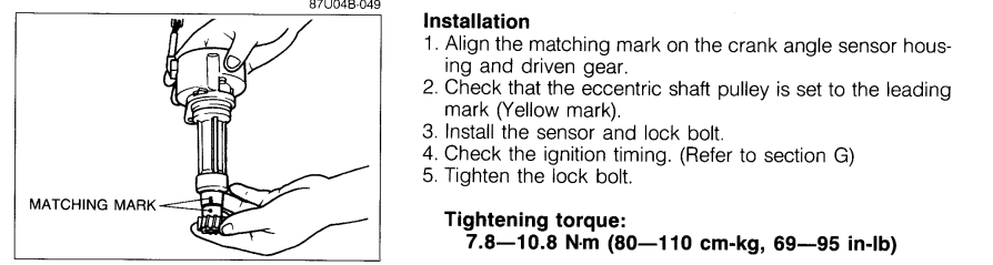
half the problems people have are from having crappy and/or mismatched pulleys
The key is... make sure the pulley and the hub that it bolts to are from the same engine. In the 2nd gen factory service manual it explains how to install it. You want to line the teeth up and drop it in. Here's a tip: with a power steering pulley unbolted it is easier to drop it in without the teeth moving out of alignment. Then you start the engine and put your timing light pickup on a leading wire. Turn the CAS to line it up with the yellow mark. If it is a stock ECU, make sure you jumper the initial set connector (see fuel and emissions section of the FSM). If it is a standalone, lock the timing at -5L -20T.
half the problems people have are from having crappy and/or mismatched pulleys
Thread Starter
Joined: Jun 2005
Posts: 2,753
Likes: 5
From: Seattle, Washington
so bear with me. this is in no way a 'stock' tii motor and is installed in a FB chassis (no a/c no p/s, relocated alt ect) not FC
motor is a S5 Tii with all S5 tii internals
power FC standalone ecu
front cover is from a GSLSE 13b, pointer is able to swivel. maybe i have it pointing in the wrong spot ?
pulley looks to be off a FD, I have never seen this pulley before but it has 3 or 4 groves on it. and is held on by only one nut which tightens down on the eshaft (not 4 bolts like standard FCs)
here is a pic of where the timing should be.
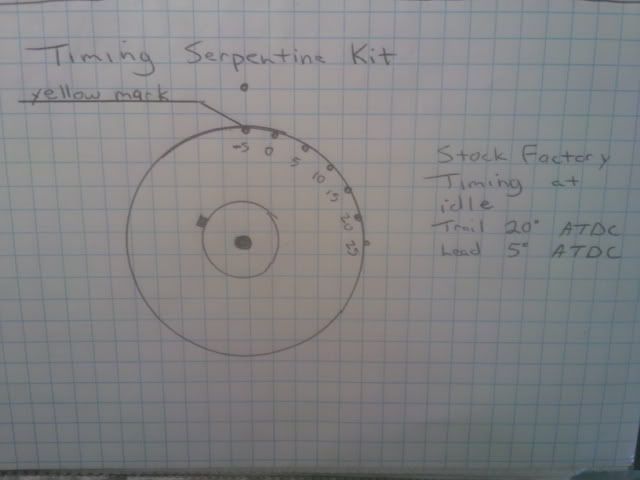
When i set the motor here and stab the CAS like i should the motor will not start or will start but run anywhere from 2k-6k rpms. ugh i know
how do you "lock timing"
motor is a S5 Tii with all S5 tii internals
power FC standalone ecu
front cover is from a GSLSE 13b, pointer is able to swivel. maybe i have it pointing in the wrong spot ?
pulley looks to be off a FD, I have never seen this pulley before but it has 3 or 4 groves on it. and is held on by only one nut which tightens down on the eshaft (not 4 bolts like standard FCs)
here is a pic of where the timing should be.
When i set the motor here and stab the CAS like i should the motor will not start or will start but run anywhere from 2k-6k rpms. ugh i know
how do you "lock timing"

Joined: Mar 2001
Posts: 31,837
Likes: 3,234
From: https://www2.mazda.com/en/100th/
http://www.racingbeat.com/RX7-1986-1...tem/11469.html
is that your pulley? the RB pulley has different marks from stock, so even if you don't have the RB pulley, you need to find out what the marks on the pulley mean.
also it doesn't matter if you have PS, or if in a different chassis, an S5 t2 motor is an S5 t2 motor...
is that your pulley? the RB pulley has different marks from stock, so even if you don't have the RB pulley, you need to find out what the marks on the pulley mean.
also it doesn't matter if you have PS, or if in a different chassis, an S5 t2 motor is an S5 t2 motor...

Trending Topics
This is how I did it for two 13B FC engines who's pulleys were not stock and both were improperly marked for top dead center.
(1) remove #1 rotor plugs
(2) rotate E shaft to approximate #1 TDC
(3) insert long thin hard metal rods like a bicycle spoke or coat hanger into both plug holes so that they touch the rotor face. Has to be thin enough to go through
the trailing small spark plug rotor housing hole.
(4)One person pushes on the rods to keep them touching the rotor face.
The second person slowly rotates the e shaft back and forth to find the point where both rods barely move in opposite directions.
If you have an engine that you know TDC, use it to find the position of the
Woodruff pulley key as a reference.
how do you "lock timing"
If you have a Datalogit box you can set your idle speeds to 0 and turn off "Idle IG Control." This turns over all ignition timing control to the IGL and IGT maps. Set the IGL to -5 and the IGT to -20. Use your Power FC Commander or your Datalogit FC-Edit monitor screen to make sure that the ECU is currently reading -5L and -20T.
Thread Starter
Joined: Jun 2005
Posts: 2,753
Likes: 5
From: Seattle, Washington
This is how I did it for two 13B FC engines who's pulleys were not stock and both were improperly marked for top dead center.
(1) remove #1 rotor plugs
Front housing i assume?
(2) rotate E shaft to approximate #1 TDC
How would i be able to tell where TDC is ? sounds like i need to rotor flat against the side with the spark plugs like it would be when they ignite ?
(3) insert long thin hard metal rods like a bicycle spoke or coat hanger into both plug holes so that they touch the rotor face. Has to be thin enough to go through
the trailing small spark plug rotor housing hole.
(4)One person pushes on the rods to keep them touching the rotor face.
The second person slowly rotates the e shaft back and forth to find the point where both rods barely move in opposite directions.
I will give this a try next time I have a helper to do this
If you have an engine that you know TDC, use it to find the position of the
Woodruff pulley key as a reference.
no spare engine
I don't know if your timing is correct or not. But I do know that somewhat incorrect timing is not necessarily going to make it run like that. It sounds like you have a tuning issue with your Power FC. If I had to bet, it's too lean.
If you have a Power FC, make sure "Idle IG Control" is OFF under the etc. --> function select menu. Your timing will be locked at -5L -20T until you reach the temperature at which the e-fan output engages which is over 200F on a default calibration.
If you have a Power FC, make sure "Idle IG Control" is OFF under the etc. --> function select menu. Your timing will be locked at -5L -20T until you reach the temperature at which the e-fan output engages which is over 200F on a default calibration.
I will look through the commander tonight and turn this option to OFF. Could my e-fan not being wired up make a difference when i go to start the engine? The previous ecu mapping was done professionally by kan and literally nothing has changed. The previous mapping was very good up until it finally broke (24k miles of abuse on a non rebuild jdm front clip) The fan was wired to turn on at 84c coolant temp btw
If you can start the engine and keep it alive by keeping your foot on the gas, in my experience it is often a matter of it being too lean. If you have an on-board wideband display, keep your foot on the gas until the sensor warms up. Watch the gauge as you slowly close the throttle. If you see the AFR getting leaner and leaner as rpms drop, that could be your issue. As a temporary measure, use the diagnostic screen to increase fuel. Try adding 10% the first time.
In fact, go into the diagnostic screen and set INJ to 1.10 just as a first test. This applies an across-the-board fuel correction that automatically goes away when you take the key out of the ignition.
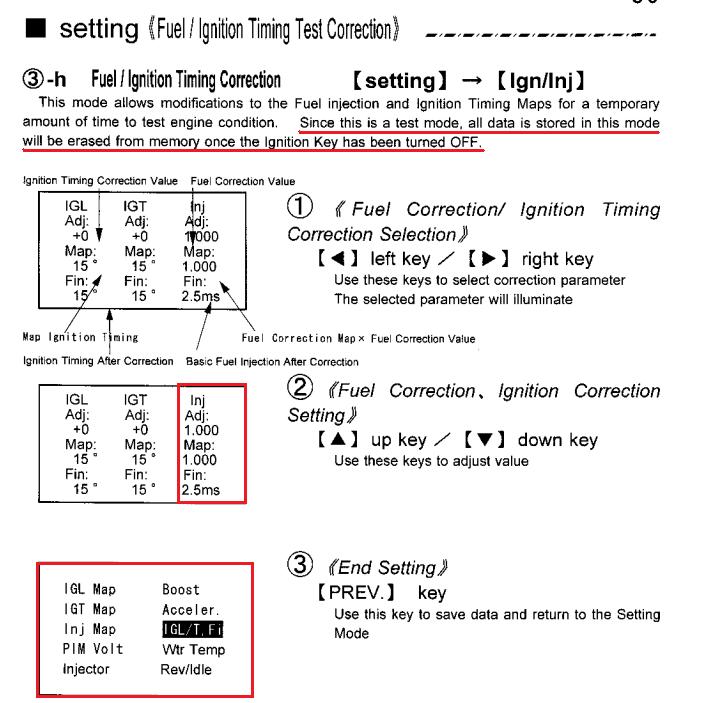
Try 1.15 and 1.20 if 1.10 doesn't help. If none of those help, it's probably not a matter of it running lean. Then try ignition changes such as +10, +15, or +20 to advance both leading and trailing (use - to retard).
Have you done a pressure test to verify you have no air leaks?
Thread Starter
Joined: Jun 2005
Posts: 2,753
Likes: 5
From: Seattle, Washington
thanks, I'm wanting to set the timing.
I will not be changing fuel values. I would appreciate anyone that posts to respect this and once I'm able to determine that the timing is correct, then and only then will i consider adjusting fuel maps
would not having the fan wired have an effect on timing ?
I will not be changing fuel values. I would appreciate anyone that posts to respect this and once I'm able to determine that the timing is correct, then and only then will i consider adjusting fuel maps
would not having the fan wired have an effect on timing ?
Joined: Mar 2001
Posts: 31,837
Likes: 3,234
From: https://www2.mazda.com/en/100th/
thanks, I'm wanting to set the timing.
I will not be changing fuel values. I would appreciate anyone that posts to respect this and once I'm able to determine that the timing is correct, then and only then will i consider adjusting fuel maps
would not having the fan wired have an effect on timing ?
I will not be changing fuel values. I would appreciate anyone that posts to respect this and once I'm able to determine that the timing is correct, then and only then will i consider adjusting fuel maps
would not having the fan wired have an effect on timing ?
Thread Starter
Joined: Jun 2005
Posts: 2,753
Likes: 5
From: Seattle, Washington
I don't know how to find tdc, let alone verify it.
That is the whole point of this thread is to find/verify timing!!!!!!
i have put 200 hours into this build over the last 21 months and done absolutely every single fricking thing on my own or with a friends assistance , this is my first car restoration and I'm not some super duper pro mechanic that knows what they hell you mean when you say "go set it to TDC" I would not be here asking HOW ITS DONE if i already knew. I'm sick of people telling me to do something I don't already know how to do and then not explaining how the f its done properly. I have made countless threads in every imaginable section of this forum and no one can get me going the right direction.
Last edited by notveryhappyjack; Oct 20, 2011 at 06:22 PM. Reason: i have to vent here for a second
Thread Starter
Joined: Jun 2005
Posts: 2,753
Likes: 5
From: Seattle, Washington
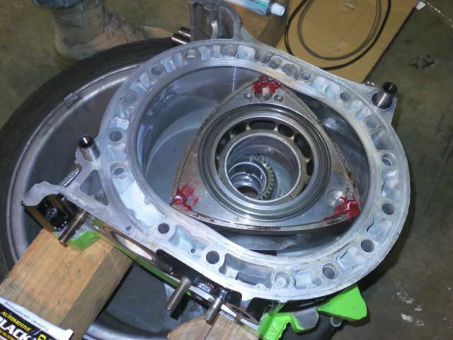
would the position I place the front rotor during the build effect timing ? Just watched Aaron Cakes youtube on how to assemble on of these and the front rotor was placed pointing downwards at the oil pan area. basically opposite of how mine is shown
this is where the front rotor was positioned during the assembily process
this is where the front rotor was positioned during the assembily process
buy a new OEM pulley and hub set for your engine. That's what I did. 100% guaranteed correct timing marks if you buy the correct part for the application. It was $190 from Malloy Mazda a couple years ago. people spend way more money than that on trivial stuff for their car
That is what the manual shows.
My friend who taught me how to do it was a previous shop owner. His method was different with #1 rotor at TDC. That way after assembly, you could verify TDC. That is the #1 rotor having a face facing perpendicular to the plane the spark plugs holes are in.
My friend who taught me how to do it was a previous shop owner. His method was different with #1 rotor at TDC. That way after assembly, you could verify TDC. That is the #1 rotor having a face facing perpendicular to the plane the spark plugs holes are in.
would the position I place the front rotor during the build effect timing ? Just watched Aaron Cakes youtube on how to assemble on of these and the front rotor was placed pointing downwards at the oil pan area. basically opposite of how mine is shown
this is where the front rotor was positioned during the assembily process
this is where the front rotor was positioned during the assembily process
Thread Starter
Joined: Jun 2005
Posts: 2,753
Likes: 5
From: Seattle, Washington
can i remove the pulley from the eshaft without ruining my eshaft freeplay/endplay ?
also from my pic it already looks like my rotors are perpendicular to the plane the spark plugs are at, kinda opposite of how I'm interrupting your thought. Are you sure this is the same way?
are we sure that no matter the initial position of the rotors during the build, no matter what... the key way at the 9 o clock position is where the timing needs to be about?
Joined: Mar 2001
Posts: 31,837
Likes: 3,234
From: https://www2.mazda.com/en/100th/
can i remove the pulley from the eshaft without ruining my eshaft freeplay/endplay ?
also from my pic it already looks like my rotors are perpendicular to the plane the spark plugs are at, kinda opposite of how I'm interrupting your thought. Are you sure this is the same way?
are we sure that no matter the initial position of the rotors during the build, no matter what... the key way at the 9 o clock position is where the timing needs to be about?
also from my pic it already looks like my rotors are perpendicular to the plane the spark plugs are at, kinda opposite of how I'm interrupting your thought. Are you sure this is the same way?
are we sure that no matter the initial position of the rotors during the build, no matter what... the key way at the 9 o clock position is where the timing needs to be about?
and yes on every 2 rotor Mazda has ever made the keyway will be @9 o clock when rotor #1 (the front one) is @ tdc.
then you can see which mark on that pulley is TDC, restab the CAS (if needed) and then start it and check the timing running.
once that agrees you can move on
Thread Starter
Joined: Jun 2005
Posts: 2,753
Likes: 5
From: Seattle, Washington
ok thanks
next question
how would i remove that bolt on the pulley ? I would need something to hold the flywheel in place right ? Leave the car in gear ? use a pry bar through the flywheel access panel ?
next question
how would i remove that bolt on the pulley ? I would need something to hold the flywheel in place right ? Leave the car in gear ? use a pry bar through the flywheel access panel ?
Joined: Mar 2001
Posts: 31,837
Likes: 3,234
From: https://www2.mazda.com/en/100th/
I would advise against taking the eshaft Bolt off if for whatever reason the hub moves you could have one of the needle bearings slide out of place which can cause a disaster later. I would just go with a stock pulley to at least stab the CAS.

