
Latest Experiment…Failure!

Thread Starter
"Elusive, not deceptive!”
Joined: May 2007
Posts: 930
Likes: 13
From: Slidell, LA
Adam,
My thoughts exactly. But if check the Downing/Emanuel " How to modify...." and a few other race builders' pictures very closely you will see the cuts.
I am thinking that since we need to flatten the surface across the plug area what we need to do is increase the temperature in the carbon stained areas and drop the temp at the plug. So I am going to try this next.
The slotted/cut spoke will concentrate the cooling conduction effect to the plug boss but not to the housing. Maybe added grooving perpendicular to water flow would also help.
Barry

Another Idea that might be stupid. Sine we just need more surface area, why not use something like Radiator fins and put them on the inside? Not sure if it would work on the same principle or not.
^ not necessarily stupid, but being that the fins would be exchanging heat with the rotor housing rather than with air (as in the case of the radiator), they would need to be well affixed to the coolant passage walls since their ability to remove heat would be limited to their ability to conduct it to the housing. This would be a very difficult procedure in so far as i can imagine.
Thread Starter
"Elusive, not deceptive!”
Joined: May 2007
Posts: 930
Likes: 13
From: Slidell, LA
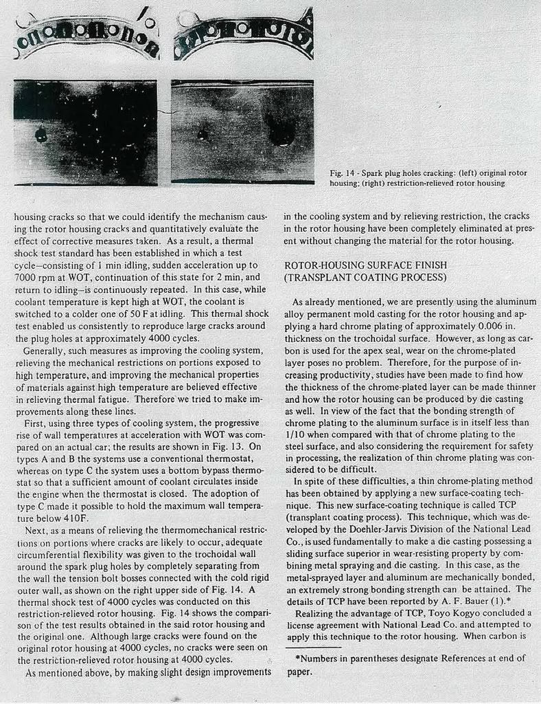
We need to visualize these two images.
Where is heat and how do we transmit it away from this concentrated hot area?
Adam’s extra plumbing is great but I think he should cut the support next to the housing so it doesn’t conduct to the housing. All of that fin’s cooling ability should go to cool the plug.
Barry
Where is heat and how do we transmit it away from this concentrated hot area?
Adam’s extra plumbing is great but I think he should cut the support next to the housing so it doesn’t conduct to the housing. All of that fin’s cooling ability should go to cool the plug.
Barry
A closer look into mazda's new engine might help. The mighty 16X ... Now i can't really tell but doesn't the trailing look like its just the circle sleeve around the sprak plug that is left on? There also seems to be more area for the water to travel through around the leading.

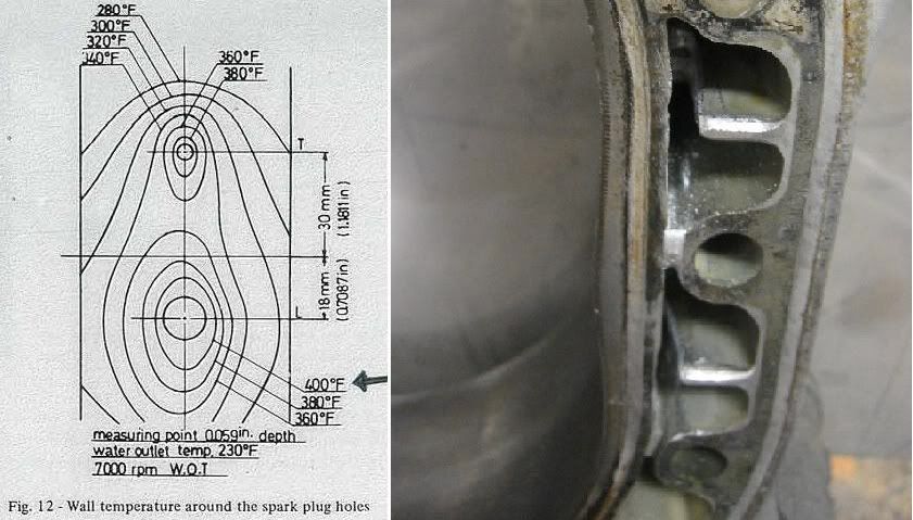
The rotor housing temperature spread graph is rather eye opening. That's for an NA motor as well. I wonder if localized boiling around the spark plugs is occurring? If so, it would be compounding the issue of large heat variance along the face. Still, I'm really hesitant to cut out any of the structure, especially since I would like to run higher boost later on when I run C16 and AI. As far as additional cooling, I think I will go forward with your idea Barry of integrating the three engine bolt holes to the cooling system. I will bore the holes out another 2mm to increase volume as well.
While on the subject of cooling, I noticed an interesting detail on the front housing. The leading spark plug coolant port is rather restrictive compare to the Trailing port. A dowel pin boss is in the way. I did a little porting, nothing real significant due to the tight space afforded, but it should help a little.
Barry,
It would sure be nice to have that pressure analyser to record what are the actual combustion pressures are, tuning would be a lot more straight forward.
Last edited by afgmoto1978; Jun 18, 2008 at 01:30 AM.
'Tuna'
Joined: Feb 2001
Posts: 4,637
Likes: 3
From: Miami,Fl,USA
From my experience in high power combinations I would not cut out the structure around the housings. That area is the first to deform and deflect under high or abnormal combustion pressures. I have many housings where you can clearly see the difference in the shape of the inner liner.
A more probable method would be to only remove partial or the area closer to the sparkplug boss instead of complete removal.
Mazda has some different stuff done to renesis housings in the water jacket area. I don't have any housings laying around to take any pics but there's deffinately differences.
Thread Starter
"Elusive, not deceptive!”
Joined: May 2007
Posts: 930
Likes: 13
From: Slidell, LA
A closer look into mazda's new engine might help. The mighty 16X ... Now i can't really tell but doesn't the trailing look like its just the circle sleeve around the sprak plug that is left on? There also seems to be more area for the water to travel through around the leading.
Good example,dj55b, it looks like the larger 16X housing allows larger cooling tunnels.
Barry
Thread Starter
"Elusive, not deceptive!”
Joined: May 2007
Posts: 930
Likes: 13
From: Slidell, LA
From my experience in high power combinations I would not cut out the structure around the housings. That area is the first to deform and deflect under high or abnormal combustion pressures. I have many housings where you can clearly see the difference in the shape of the inner liner.
A more probable method would be to only remove partial or the area closer to the sparkplug boss instead of complete removal.
Mazda has some different stuff done to renesis housings in the water jacket area. I don't have any housings laying around to take any pics but there's deffinately differences.
A more probable method would be to only remove partial or the area closer to the sparkplug boss instead of complete removal.
Mazda has some different stuff done to renesis housings in the water jacket area. I don't have any housings laying around to take any pics but there's deffinately differences.
On the distorted housings, was it trauma from detonation or just high boost that was deforming them?
Barry
Thread Starter
"Elusive, not deceptive!”
Joined: May 2007
Posts: 930
Likes: 13
From: Slidell, LA
The rotor housing temperature spread graph is rather eye opening. That's for an NA motor as well. I wonder if localized boiling around the spark plugs is occurring? If so, it would be compounding the issue of large heat variance along the face. Still, I'm really hesitant to cut out any of the structure, especially since I would like to run higher boost later on when I run C16 and AI. As far as additional cooling, I think I will go forward with your idea Barry of integrating the three engine bolt holes to the cooling system. I will bore the holes out another 2mm to increase volume as well.
While on the subject of cooling, I noticed an interesting detail on the front housing. The leading spark plug coolant port is rather restrictive compare to the Trailing port. A dowel pin boss is in the way. I did a little porting, nothing real significant due to the tight space afforded, but it should help a little.
Barry,
It would sure be nice to have that pressure analyser to record what are the actual combustion pressures are, tuning would be a lot more straight forward.
While on the subject of cooling, I noticed an interesting detail on the front housing. The leading spark plug coolant port is rather restrictive compare to the Trailing port. A dowel pin boss is in the way. I did a little porting, nothing real significant due to the tight space afforded, but it should help a little.
Barry,
It would sure be nice to have that pressure analyser to record what are the actual combustion pressures are, tuning would be a lot more straight forward.
Barry
Thread Starter
"Elusive, not deceptive!”
Joined: May 2007
Posts: 930
Likes: 13
From: Slidell, LA
Here is a RX8 housing from the Atkins website. It has similar grooves on the bosses below the sparkplugs and cut webs, very much like the 16X. Again, for NA application.
Barry

Barry
Beat me to posting the pic. I wonder if the earlier years had different passage inbetween 12a's and 13b. or were they all from the same cast.
Last edited by dj55b; Jun 18, 2008 at 09:32 AM.


It would be very easy to fit a piece across the cut right at the top that would help add support yet allow a coolant passage over the casting at the plug.
Thread Starter
"Elusive, not deceptive!”
Joined: May 2007
Posts: 930
Likes: 13
From: Slidell, LA
A step machined when removing the metal (two different diameters) would keep it from moving forward. The plate holds it the other way. A slight (.0005"-.001") press in this direction, would probably be a good idea also.
One could then get complicated and try to somehow machine a V shape down the rib and/or across the bottom of the step but, I think that is unreasonable.
Last edited by user 893453465346; Jun 18, 2008 at 08:00 PM. Reason: Better discription.
Thread Starter
"Elusive, not deceptive!”
Joined: May 2007
Posts: 930
Likes: 13
From: Slidell, LA
If you look closely the 16X has the same cuts.
Barry
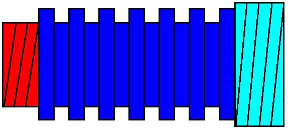
Alright I was kinda thinking about this all day and have one neat idea. What if we drill out the original leading and trailing holes where the spark plugs sit. Bore out the holes by about 1/2" more than the over all diameter of the original spark plug holder and make an insert on the lathe. Not sure if we could use Copper for its better heat tranfter but even aluminum would do. The insert would look like this. One side would thread into the inside side of the housing (Red), and the other would be on the outside(Light Blue). Sealing of the threads with a good high temp sealer would be crucial to prevent water going into the engine and loosing compression. The center section that sits in the water area is all gooved. Here's a picture that I drew up in paint :
EDIT:
Sealant could also just be a copper crush washer maybe?
EDIT:
Sealant could also just be a copper crush washer maybe?
Last edited by dj55b; Jun 18, 2008 at 10:39 PM.
Thread Starter
"Elusive, not deceptive!”
Joined: May 2007
Posts: 930
Likes: 13
From: Slidell, LA
Alright I was kinda thinking about this all day and have one neat idea. What if we drill out the original leading and trailing holes where the spark plugs sit. Bore out the holes by about 1/2" more than the over all diameter of the original spark plug holder and make an insert on the lathe. Not sure if we could use Copper for its better heat tranfter but even aluminum would do. The insert would look like this. One side would thread into the inside side of the housing (Red), and the other would be on the outside(Light Blue). Sealing of the threads with a good high temp sealer would be crucial to prevent water going into the engine and loosing compression. The center section that sits in the water area is all gooved. Here's a picture that I drew up in paint :
Sealant could also just be a copper crush washer maybe?
Sealant could also just be a copper crush washer maybe?
My thought is to use a maximum of the existing metal and direct its cooling ability to the plug by not allowing it to cool an under heated surface. I think this uneven housing surface is a main cause of broken apex seals.
