
IC endtank insert design question


IC endtank insert design question
Hi guys I built my own intrercooler to fit my needs and space requirements, and it is a little unconventional, but it seems to work very well.
My question is to anyone that has good fluids background or would like to take a stab at explaining the nuances of the problem I have please.
I have a square endtank design, and I fully understand the flow characteristics that come with such a simple design, and I am happy/accept them for what they are considering I don�t think I could find anything close to what I need that has already been produced, and I don�t have a clue who could make some custom ones for me, and I don�t have the will or time to make my own the way I would want them out of aluminum.
Now to the question: would it be a plausible thing to make a fiberglass/composite shaped insert to place inside the square/rectangular �box� endtanks and expect them to work properly?
What I would like to do is essentially make a mold that is inducive to good flow characteristics with the size tolerances that fit my core, and place the insert inside the square endtanks.
Problems I see are obviously how to seal it , and getting it inside then welding the tank shut.
If it is not sealed it would probably do more harm than good if it leakes around the sides of a insert right?
If anyone has considered this or actually has better ideas on how to build a endtank that has theoretical ideal shape and flow characteristics please tell me how you handled the issue?
I have thought about grease pressure molding but this is a tad bit out of the scope of what I feel is reasonable.
Any ideas on how to make a tank that is both professional looking and has optimum flow characteristics?
I would like to keep my square tanks and actually have inserts of some kind because of the circumstances involved with my design. It makes it much more astatically pleasing and helps seal the IC off without �tinny� looking sheetmetal or visible ductwork.

Seems you could just form an aluminum baffle/guide for the neckdown and tack weld it in place before you weld the end tank on.
You don't have to worry about boost leaking around the baffle/guide as long as the endtanks don't leak as you are just trying to guide the flow. It will be same pressure on either side of the baffle if it is not sealed so the flow will just follow the contour.
It is a bit more intake volume to fill so it won't be as good as a properly shaped end tank in that regard.
Heck, seam weld the baffle/guide inside the end tank if you are ****.
When I modded my Izusu NPR IC inlet/outlets for my Horizontal mount IC I cut out the factory casting webs that run perpendicular to flow in the end tanks because I am a nut, most people just run the IC as is.
If the end tanks are already on the IC perhaps you could pour in something like urethane and let it cure while being held at the right angle to fill the bottom corner. Just make sure not to tip it and let it fill up the IC core- that would suck...
So do you think it would be worth the time to have a �loose� insert one that could just be tacked in place even if it leaked around the sides?
My instinct tells me that the air forcing itself around and through small crevices would not be particularly good, and could cause a lot of eddies in the tank, as the reemerge from other nonsealed seems. I wonder how counter productive that would be compared to the gains from making the majority of the air flow correctly?
Maybe like you said I could get one of those guys that likes to pound sheets into forms or with an English wheel to make me a weld in insert that wouldn�t necessarily have to have a perfectly smooth finished look to it. Then I could weld it to the inside of the tank, grind and polish and pressure test before welding the final 2 part tank to the IC. If it had the support of the �box� tank, surly using something that can be readily formed would work wouldn�t you think?
Anyone have any experience with forming aluminum, want to chime in with what can be done with certain thickness of sheet?
If it where a thin enough material, it could probably be formed to even create a transition from the intake tube to a rolled cup shape that would fit against the IC.
This would also give me a chance to correct a badly located outlet I thought I had to have at the time.
Even if you were to tack a insert in place you would still see benifits of directing most of the flow where it otherwise would have missed. Assuming the baffle was fitted nice.
Last edited by Zero R; Oct 26, 2005 at 10:22 AM.
I made a custom stock mount for my FD, but plan on making a custom V-mount when I go single next year. I attached photos to give you some ideas. Visualize in you head the end tanks as funnels and treat air as a liquid, if it looks right in your head go with it.
Don't go too thin, try to stay thicker than .100 wall, if you want to form aluminum use 5052 and anneal it before you start pounding.
Good luck.
Don't go too thin, try to stay thicker than .100 wall, if you want to form aluminum use 5052 and anneal it before you start pounding.
Good luck.
Last edited by afgmoto1978; Oct 26, 2005 at 11:10 AM.
If for some reason you are worried about a welded in baffle affecting flow (which I don't believe it will)-
Simply have a properly shaped end tank welded on the IC core and weld a box around it to appease your sense of asthetics.
I think a properly shaped endtank incorporating the needed filler plate as the front of the end tank or just a plate welded on the front to fill the space would look best since form follows function according to my sense of asthetics
Originally Posted by Zero R
Even if you were to tack a insert in place you would still see benifits of directing most of the flow where it otherwise would have missed. Assuming the baffle was fitted nice.
 how much do you think it affects the pressure drop of a core to have square endtanks? Assuming a std core with ideal tanks would have 2 Psi drop what do you suppose a square tank IC would come in at?
Originally Posted by afgmoto1978
I made a custom stock mount for my FD, but plan on making a custom V-mount when I go single next year. I attached photos to give you some ideas. Visualize in you head the end tanks as funnels and treat air as a liquid, if it looks right in your head go with it.
Don't go too thin, try to stay thicker than .100 wall, if you want to form aluminum use 5052 and anneal it before you start pounding.
Good luck.
Don't go too thin, try to stay thicker than .100 wall, if you want to form aluminum use 5052 and anneal it before you start pounding.
Good luck.
I would like to see the back side of the IC if possible please?
And how do you plan on making the profiles that you posted? Those seem like they would be very hard to produce without the proper machinery?
Originally Posted by BLUE TII
If for some reason you are worried about a welded in baffle affecting flow (which I don't believe it will)-
Simply have a properly shaped end tank welded on the IC core and weld a box around it to appease your sense of asthetics.
I think a properly shaped endtank incorporating the needed filler plate as the front of the end tank or just a plate welded on the front to fill the space would look best since form follows function according to my sense of asthetics
Simply have a properly shaped end tank welded on the IC core and weld a box around it to appease your sense of asthetics.
I think a properly shaped endtank incorporating the needed filler plate as the front of the end tank or just a plate welded on the front to fill the space would look best since form follows function according to my sense of asthetics
Originally Posted by BLUE TII
I think a properly shaped endtank incorporating the needed filler plate as the front of the end tank or just a plate welded on the front to fill the space would look best since form follows function according to my sense of asthetics
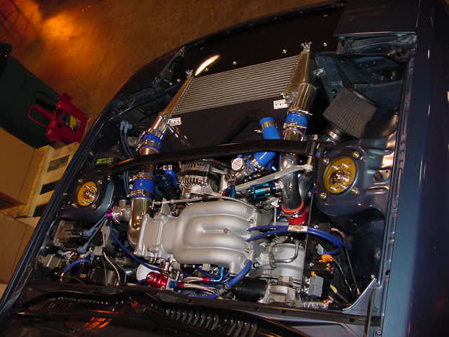
this pic shows the location of my IC tubes, obviously I would need two completely different profiles.
Trending Topics
this pic shows the location of my IC tubes, obviously I would need two completely different profiles.
Not if you clocked your turbo compressor to point up and toward the engine a bit. Then you could have both the inlet and outlet feeding from the top and have a more gradual bend in the turbo outlet pipe.
See how the turbo outlet pipe is on my horizontal mount IC set up.
Do it up like that, but over towand the engine and curve it back down and out to the IC. If you look at other V-mount FDs you can get some good ideas.
Originally Posted by rotarypower101
I don�t think I would put it in otherwise but thanks for the input Sean how much do you think it affects the pressure drop of a core to have square endtanks? Assuming a std core with ideal tanks would have 2 Psi drop what do you suppose a square tank IC would come in at?
how much do you think it affects the pressure drop of a core to have square endtanks? Assuming a std core with ideal tanks would have 2 Psi drop what do you suppose a square tank IC would come in at?
Originally Posted by rotarypower101
I would need two completely different profiles.

Thread
Thread Starter
Forum
Replies
Last Post
Adaptronic S5 Turbo PNP Unit questions
_Tones_
Adaptronic Engine Mgmt - AUS
10
May 25, 2021 05:37 AM
AMOC
SE RX-7 Forum
1
Sep 10, 2015 09:42 AM
Nosferatu
2nd Generation Specific (1986-1992)
7
Sep 5, 2015 02:13 PM
rx8volks
Canadian Forum
0
Sep 1, 2015 11:02 PM