
ball joint tapered cones


ball joint tapered cones
I forgot the technical name of those tapered cones people use to bolt up spherical bearings into spindles. Anyone know where to buy them? I wonder if its the same fitment as another application. Anyone know? I'm interested in fabricating front lower spherical bearings.

Old [Sch|F]ool


Joined: May 2001
Posts: 12,880
Likes: 577
From: Cleveland, Ohio, USA
IIRC the thing to to is aircraft grade 18mm bolt with the head cut off and a channel cut into it so you can clamp it in the upright.
At least, I THINK it was 18mm. The common sizes for this style ball joint are 17, 18, and 19mm, and I play with a bunch of VW stuff and they're similar but different and had a couple sizes over the years.
At least, I THINK it was 18mm. The common sizes for this style ball joint are 17, 18, and 19mm, and I play with a bunch of VW stuff and they're similar but different and had a couple sizes over the years.
Your post did give me an idea though. I'll post pictures tomorrow night :-)
Old [Sch|F]ool
Joined: May 2001
Posts: 12,880
Likes: 577
From: Cleveland, Ohio, USA
Andrew Havas's rally car used aircraft bolts in the uprights in exactly the manner I described, and fabricated control arms.
There was a somewhat infamous picture of when he rolled at a rally after he broke his wrist from driving one-handed (broken trans - had to hold it in gear) and both control arms were pulled apart but the spherical bearings were still attached to the uprights. So the method is clearly strong enough
There was a somewhat infamous picture of when he rolled at a rally after he broke his wrist from driving one-handed (broken trans - had to hold it in gear) and both control arms were pulled apart but the spherical bearings were still attached to the uprights. So the method is clearly strong enough
AWR Racing has a roll center correction kit that uses the early a arms with the bolt in ball joint. I just installed the kit on my 7. After looking at it, someone with good fab skills could make the same set up with a little machine work.
Trending Topics
Rotary Enthusiast
Joined: Mar 2001
Posts: 815
Likes: 0
From: Vancouver, BC, Canada

^yup, you can see the line in mine when it broke:
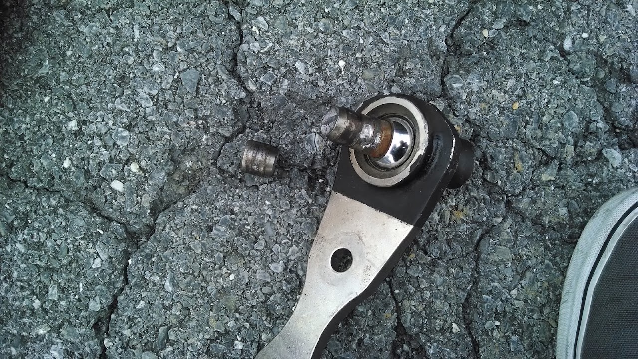
the pin broke right at the pinch joint.
the reason is 2 fold:
1 - it's recessed all around like the stock pin is so the smallest diameter is only 15mm.
2 - there is nothing to tighten the spacer to the knuckle, so it's not supporting the pin at all to prevent more side loads.
the pin broke right at the pinch joint.
the reason is 2 fold:
1 - it's recessed all around like the stock pin is so the smallest diameter is only 15mm.
2 - there is nothing to tighten the spacer to the knuckle, so it's not supporting the pin at all to prevent more side loads.
Andrew Havas's rally car used aircraft bolts in the uprights in exactly the manner I described, and fabricated control arms.
There was a somewhat infamous picture of when he rolled at a rally after he broke his wrist from driving one-handed (broken trans - had to hold it in gear) and both control arms were pulled apart but the spherical bearings were still attached to the uprights. So the method is clearly strong enough
There was a somewhat infamous picture of when he rolled at a rally after he broke his wrist from driving one-handed (broken trans - had to hold it in gear) and both control arms were pulled apart but the spherical bearings were still attached to the uprights. So the method is clearly strong enough
I drilled out the pinch area to 3/4" (19mm) (which took way longer than I thought it would for just 1mm larger). I notched a 3/4" grade 8 bolt and hammered it through the top and pinched it in place.
the bearing spacers and bolt length need tweaking...
Old [Sch|F]ool
Joined: May 2001
Posts: 12,880
Likes: 577
From: Cleveland, Ohio, USA
I was considering boring them out to 19mm so I can use GM N-body control arms. The ones for, say, an '05 Malibu or G6 are about the same as FC but longer, and the rear bushing is more conducive to the kind of geometry alterations I want to make.
Y'know, I DO have a spare set of uprights...
Y'know, I DO have a spare set of uprights...
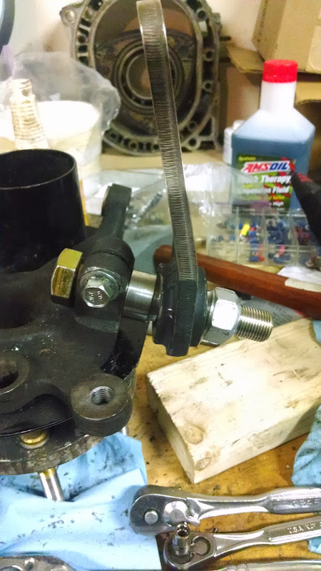
Finished my modded AWR ball joints:
I drilled out the pinch area to 3/4" (19mm) (which took way longer than I thought it would for just 1mm larger). I notched a 3/4" grade 8 bolt and hammered it through the top and pinched it in place.
the bearing spacers and bolt length need tweaking...
I drilled out the pinch area to 3/4" (19mm) (which took way longer than I thought it would for just 1mm larger). I notched a 3/4" grade 8 bolt and hammered it through the top and pinched it in place.
the bearing spacers and bolt length need tweaking...
how much did you space it out compared with stock?
Are you using a snap ring to hold the bearing in place?
the actual ball joints are AWR units and yes they have snap rings in the containers, but you have to be careful how you clock them or they limit the articulation which sucks. your best bet is to put them towards the front of the car (caster tilts the strut back)
They're using a QA1 WPB12T bearing.
!
the AWRs were spaced out 1", in the picture that is currently 0.75"... I haven't decided what I'm going to space it out yet. we'll see. I'll probably measure some stuff to find out where my roll center actually is first.
the actual ball joints are AWR units and yes they have snap rings in the containers, but you have to be careful how you clock them or they limit the articulation which sucks. your best bet is to put them towards the front of the car (caster tilts the strut back)
They're using a QA1 WPB12T bearing.
the actual ball joints are AWR units and yes they have snap rings in the containers, but you have to be careful how you clock them or they limit the articulation which sucks. your best bet is to put them towards the front of the car (caster tilts the strut back)
They're using a QA1 WPB12T bearing.
At first I was thinking of a design like that, but now I am curious on a threaded length to adjust length and adjusting the position of the bearing. Hmmmmmm
Cool, thanks! Do you have a picture of the limiting articulation. Is the bearing more towards one side when sitting?
At first I was thinking of a design like that, but now I am curious on a threaded length to adjust length and adjusting the position of the bearing. Hmmmmmm
At first I was thinking of a design like that, but now I am curious on a threaded length to adjust length and adjusting the position of the bearing. Hmmmmmm

I've already ordered new bearing spacers that I'm going to modify and see how they work, I'll keep my build thread updated.
are you talking about adjusting the length of the control arm? that's going to be pretty hard without putting some serious bending loads through a rod end.
have you checked with the car on the ground, 4 post lift, or with suspension suspension raised to your ride height? I can't see the front to back lean, but your saying more positive caster would allow more movement as well?
Also, I noticed your ball joint is mounting on top of the control arm. Mine are at the bottom
Also, I noticed your ball joint is mounting on top of the control arm. Mine are at the bottom
I was saying you should put the circlip holes towards the front (on top, towards the back on the bottom) because it's less likely to interfere with things...

Thread
Thread Starter
Forum
Replies
Last Post
Turblown
Vendor Classifieds
12
Oct 17, 2020 03:25 PM
joel(PA)
Group Buy & Product Dev. FD RX-7
8
Oct 4, 2015 06:07 PM