When you click on links to various merchants on this site and make a purchase, this can result in this site earning a commission. Affiliate programs and affiliations include, but are not limited to, the eBay Partner Network.
Sorry for my late responce. and finally I find solution for this problem.
Yes. it is contrast problem. earlier commander has fcc2 version main board. and later version of Commander has fcc3 version board. fcc3 board has contrast problem.
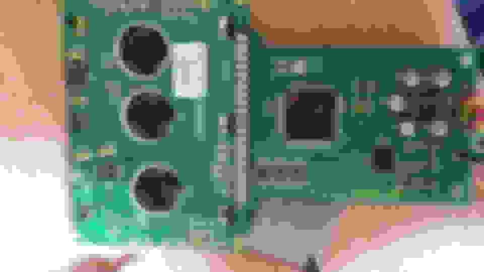
FCC3 version main board.
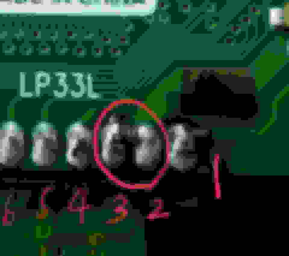
apply 1.2kohm resister between LCD #2~#3 pin. and cut #18 pattern.
Sorry for my late responce. and finally I find solution for this problem.
Yes. it is contrast problem. earlier commander has fcc2 version main board. and later version of Commander has fcc3 version board. fcc3 board has contrast problem.
FCC3 version main board.
apply 1.2kohm resister between LCD #2~#3 pin. and cut #18 pattern.
Detail picture of resister.
hope this help everyone~ thanks.
Thanks Jin-74 on your replied... It was hard on contacting you... I even try searching you at rx7 Facebook group...
Anyway later I'll try to connect resistor between those 2 pins since right now I don't have any resistor... Below is my FC commander...
Pretty sure I found an LCD that will work and it is located stateside. Question: If I have the old FCC2 board, do I still have to install a resistor between the #2 and #3 pin and cut pin 18? It appears from the write up that cutting pin 18 and wiring in the resistor is only required on FCC3 board. Is that correct?
Pretty sure I found an LCD that will work and it is located stateside. Question: If I have the old FCC2 board, do I still have to install a resistor between the #2 and #3 pin and cut pin 18? It appears from the write up that cutting pin 18 and wiring in the resistor is only required on FCC3 board. Is that correct?
FCC2 board do not need resistor. but it has to cut pin 18. thanks~
I just did this on an FCC3 Board with a display that I finally found! It took many hours of searching for it but I now have a source for the screens. I have some tips for everyone who wants to try doing this.
1) Take the two screws out of the back of the Commander and the back cover should separate easily from the front.
2) If you don't know how to solder a circuit board, stop here and find someone who does. That what I did and many, many thanks, to my friend Mark who helped me out here.
3) Set your adjustable solder iron to 280C. Too hot and you are just going to burn stuff up. and SMD workstation is available from e-bay for about 60 bucks. Way worth it. Use a really fine pointed solder tip. Make sure to keep it tinned, which is really just a small amount of solder on the tip.
4) Heat each pin individually until they are ready to pull out. These pins are small and if you don't have a good work area and really fine tweezers, stop here. If you do have a good lighted work area, then continue.
5) pull all twenty pins.
6) go back and heat each hole that is filled with solder until it becomes liquid. Use a solder sucker (also available on e-bay) to suck up the solder while it's hot.
7) once you have removed as much solder as possible, the lcd should separate from the main board. A little coaxing doesn't hurt it, just don't break the damn thing.
9) Line up the holes on the LCD board with the driver board or main board. Solder in pin one and pin twenty. That will hold your LCD display board in place while you solder the remaining 17 pins. Yes I said 17.
10) when you get to hole 18, leave that pin out. Do not connect pin 18. It has something to do with negative voltage which I do not understand and quite frankly don't care about as long as it works.
11) when you have all the pins soldered in and are satisfied with your work, pin 18 should have a race (that's what they call it) coming from it that you can see on the circuit board. That's what carries the negative voltage I guess. Get a razor blade and cut that race just to make sure that nothing is flowing through it.
12) Each LCD replacement board has different requirements for resistors to get the resistance right. for previous posters it was a surface mounted resistor of 1.2kOHM which in layman's terms is 1200. The resistors, also available on e-bay dirt cheap, must be soldered in between pin two and pin three.
13) To find the resistance you need, solder a spare wire into pin two and one into pin three. Hook up a potentiometer (variable resistor) to those two wires.
14) plug in your commander to the PFC. turn ignition on. The LCD will probably look like crap. Too bright or too dark, perhaps you can see letters from an angle. adjust the potentiometer until you have a good picture on the screen. The display should be sharp and clear.
15) Turn off your ignition. unhook the variable resistor. Don't mess with the **** at all.
16) Hook up a volt meter, even one from harbor freight will work and find the resistance of the variable resistor. Mine was 650 ohms.
17) since I had 1.2kOHM resistors already, I needed to figure out how to get to 650 or thereabouts. My friend Mark suggested stacking two of the resistors I had between pin two and three. He did that which basically made a 610 OHM resistor. Plugged the commander in, turned on the key, and the results were perfect. I will try to post up pics of my display one I figure out how to do it. It looks just like the previous successful posters pics.
Pretty sure I found an LCD that will work and it is located stateside. Question: If I have the old FCC2 board, do I still have to install a resistor between the #2 and #3 pin and cut pin 18? It appears from the write up that cutting pin 18 and wiring in the resistor is only required on FCC3 board. Is that correct?
So why don't I see a link to where to purchase the screen you used lol. No but please share with us where to buy this screen it looks 100% better great work. Thanks
Quick update: I almost got everything to work. Sadly, I have trouble cutting pin 18. Is it ok to "insulate" it between the 2 boards? Slipping something in between looks easier than scraping it with a razor blade. By the way I used a 1kohm resistor since I didn't have a 1.2k. Somewhat legible for now until I get a variable resistor.
Pin 18 should be removed completely. Just heat it and pull it. Don't slip something in between. You only need to cut the race. Its a little copper "lane" that comes from hole 18 on the board. Get a razor blade and cut the race crosswise thereby cutting off the flow of electricity from the source to where pin 18 is supposed to go.
Pin 18 should be removed completely. Just heat it and pull it. Don't slip something in between. You only need to cut the race. Its a little copper "lane" that comes from hole 18 on the board. Get a razor blade and cut the race crosswise thereby cutting off the flow of electricity from the source to where pin 18 is supposed to go.
Did I cut too deep? Is that copper underneath that etching? (Ignore the resistor, still testing for the right value since I don't have a variable resistor). If I messed up, I'm gonna go backwards and solder back the original display...