
Power FC PFC wasgate/Precontrol


Why would fuel cut be involved in the boost control process? That would be a pretty savage way of controlling boost.
or is that number only there so it can calculate the fuel cut,
1.00 + .25 = fuel cut of 1.25 kg/cm^2 ?
Is the "boost level" essentially a target lambda (as is used in OEM fuel maps)? you need to understand a bit of control theory and how OEM electronic boost control systems work. They are far more sophisticated than aftermarket ones. "real" boost controllers, the ones that OEM's spend millions of dollars on, don't just have a solenoid duty cycle value with some crude fuzzy logic algorithm. "if boost is too high, lower it" would be a fuzzy logic control statement. OEM's have a target boost value and a ton of tables that allow them to hone in on that value under all conditions.
Most modern OEM boost control systems have a target boost table of rpm vs engine load vs target boost. This may correspond to the "boost" setting in the PFC, which is what my question was getting at. Then a modern OEM boost control system has several tables of base duty cycle values, equivalent to the "duty" value in the PFC. Read http://www.cobbforums.com/forums/ima...ubarusv111.pdf , page 20.
From there, modifications to the actual duty cycle being used are made based on how much authority you give the closed loop system to change the duty cycle values. It's like telling a cruise control computer the range of throttle it is allowed to give in order to keep the speed near the set value. In the case of boost control, Subaru for example would call this a "turbo dynamics" table--similar to what is used to determine how much timing can be pulled in response to a particular aggregate knock reading. Then there are even more tables to compensate based on ambient conditions, etc.
Think about a Greddy Profec. It's a pretty dumb EBC, although it gets the job done for limited aftermarket applications. You can't even set a target value precisely. AVC-R isn't much better, even though they market themselves as such. The AVC-R is like an original NES and a Profec is like an old Atari. Maybe the Power FC is more sophisticated? The PFC was originally for the series 7 and is probably an aftermarket copy of what I suspect to be more advanced series 7 (96+) OEM control logic. We just don't know how it works, and there are a lot of hidden values that we can't change. I'm perhaps giving Mazda and Apex'i more credit than is normally given to them here. The more you learn about OEM hardware (and not 80s level stuff like on the series 6 ECU), the more you realize just how crude of electronics we are tinkering with here with our aftermarket controllers.
the secondary number is used to control the wastegate after transition, so the relative magnitude should not matter.
The wastegate goes from being effectively full open to a number right near the target duty cycle.
I'm starting to verify some of my suspicions about the way the PFC boost control system works. There is simply no way that the "boost" setting is merely a fuel cut. It affects wastegate crack pressure. If boost were controlled exclusively by the "duty" setting, it stands to reason that, in a single turbo application (sequential turbo control off), the wastegate solenoid would go almost immediately to the set duty cycle as soon as the car gets into boost. But it doesn't. The wastegate and precontrol solenoids switch to a value near their set duty based on some kind of crack pressure setting/calculation.
On a sequential car, the "primary" boost setting appears to be related the precontrol crack pressure. On a single turbo application, the wastegate solenoid seems like it will be at full duty (pushing the wastegate closed) unless boost gets somewhere near one of those "boost" settings, and I suspect it would be "secondary". I don't have a running single turbo car to run any tests, but I do have an old datalog from my old setup. This was with all "boost" settings set to 2.00 , effectively eliminating fuel cut. The "duty" values were not touched.
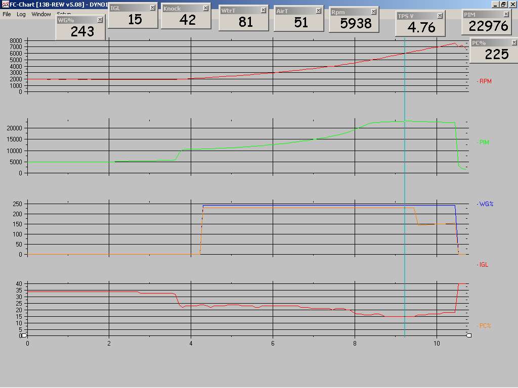
Here is a log of wastegate duty cycle output on a single turbo car. You can see that the wastegate solenoid effectively remains completely open (wastegate itself would remain shut b/c of the pressure being applied). Despite sequential turbo control being disabled, for some odd reason the PFC still sends out a precontrol duty signal. The precontrol signal, for reasons unknown to me at this point, drops to the set "primary" duty a little over 6000rpms or so. I've seen this in a few of my logs, always over 6000rpm, and always a drop to the "primary" value. But the PFC manual says that total boost aka wastegate pressure is controlled by the "primary" value in single turbo applications. There is then a conflict. here. The PFC manual specifically says that boost is controlled by the "primary" setting, but my datalogs show that not to be true. It seems that, for single turbo applications, the best thing to do would be to set the same target boost and duty cycles under both "primary" and "secondary" rows instead of following the instructions and ignoring the "secondary" values.
It stands to reason then (barring additional info) that the Power FC manual is wrong. Single turbo boost control is determined first by the "boost" values for approximate crack pressure (the boost level at which wastegate duty drops to the set value). Then the boost controller duty value itself is set through the "secondary" setting, which directly contradicts the PFC instructions from Apex'i.
The "boost" value is NOT just a fuel cut! The manual is correct when it hints at that. But the wastegate solenoid duty under single turbo setups is not controlled by the "primary" value! The "primary" value still affects the precontrol output just like on a sequential car, and this log confirms it. No wonder people have so much trouble controlling single turbo boost with the PFC kit. The instructions are misleading.
On a sequential car, the "primary" boost setting appears to be related the precontrol crack pressure. On a single turbo application, the wastegate solenoid seems like it will be at full duty (pushing the wastegate closed) unless boost gets somewhere near one of those "boost" settings, and I suspect it would be "secondary". I don't have a running single turbo car to run any tests, but I do have an old datalog from my old setup. This was with all "boost" settings set to 2.00 , effectively eliminating fuel cut. The "duty" values were not touched.
Here is a log of wastegate duty cycle output on a single turbo car. You can see that the wastegate solenoid effectively remains completely open (wastegate itself would remain shut b/c of the pressure being applied). Despite sequential turbo control being disabled, for some odd reason the PFC still sends out a precontrol duty signal. The precontrol signal, for reasons unknown to me at this point, drops to the set "primary" duty a little over 6000rpms or so. I've seen this in a few of my logs, always over 6000rpm, and always a drop to the "primary" value. But the PFC manual says that total boost aka wastegate pressure is controlled by the "primary" value in single turbo applications. There is then a conflict. here. The PFC manual specifically says that boost is controlled by the "primary" setting, but my datalogs show that not to be true. It seems that, for single turbo applications, the best thing to do would be to set the same target boost and duty cycles under both "primary" and "secondary" rows instead of following the instructions and ignoring the "secondary" values.
It stands to reason then (barring additional info) that the Power FC manual is wrong. Single turbo boost control is determined first by the "boost" values for approximate crack pressure (the boost level at which wastegate duty drops to the set value). Then the boost controller duty value itself is set through the "secondary" setting, which directly contradicts the PFC instructions from Apex'i.
The "boost" value is NOT just a fuel cut! The manual is correct when it hints at that. But the wastegate solenoid duty under single turbo setups is not controlled by the "primary" value! The "primary" value still affects the precontrol output just like on a sequential car, and this log confirms it. No wonder people have so much trouble controlling single turbo boost with the PFC kit. The instructions are misleading.
AVC-R vs PFC boost control
Cliff's notes: the PFC really is just a simplified AVC-R with a few less options.
Crack pressure is the psi at which the wastegate is first opened. On my HKS 40mm wastegate, when running on the straight 10psi spring (no boost controller) the wastegate would "crack" (I could hear it vent to atmosphere) at 6psi, and would be fully open at 10. Consider this basic outline of an external wastegate:

An oversimplification perhaps, but an external wastegate operates on a pressure differential between the top and bottom of the spring essentially. With the EBC at max duty, maximum pressure is applied to the top port of the spring, pushing the wastegate shut. This is by using a normally closed ("NC") solenoid, whereby more duty "opens" the solenoid and passes more air. So at max duty (during initial spool), maximum air/pressure is moving through the solenoid to the top port of the WG, pushing against the pressure supplied from the side port and closing the poppet valve. The approximate crack pressure would be the point at which the duty cycle drops from near maximum to right near whatever set duty value you have in the PFC. Less duty on the solenoid and the resultant lower pressure through the top port means that the pressure from the side port of the wastegate begins to win out and the wastegate valve will open (depending on the stiffness of the spring etc).
The same principle applies to the factory boost control system. The wastegate and precontrol actuators function like the the side port of an external wastegate. During spool, the wastegate or precontrol solenoid (also "NC" normally closed) is held near maximum duty, in principle venting out any pressure that would make the actuator open up (disregard all the restrictor pill crap in this model). When crack pressure is reached, duty drops to the set value in the PFC. I am still unsure exactly how this is determined in the PFC, but I believe the "boost" value is a contributer as I have said. Less duty on a normally closed solenoid means less air vents from the actuator, causing pressure to build up. This pressure pushes on the actuator, opening the flapper and lowering boost, or at least lowering the rate at which boost climbs.
Most external EBC's hide that whole crack pressure operating principle because of the learning curve involved. It is no surprise then that two EBC's which do let you set it directly are considered notoriously difficult to tune. One, the Greddy Profec Spec 2, calls crack pressure "Start Duty" :

The Apex'i AVC-R indirectly lets you set crack pressure by directly mapping duty cycle vs rpm, which is actually an even more adjustable yet complicated way to do it. I would think that you could partially emulate the control logic of the PFC if you set duty very high in the lower rpms during spool and then dropped the duty value at a higher rpm.
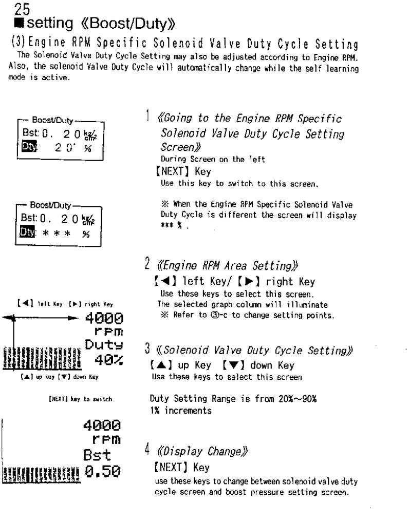
There is also a self-learning mode in the AVC-R which is also in the PFC boost control. In the following pic from the AVC-R instructions, you can see the self-learning adjusting 2% from the initial set value. I have observed that same behavior in the PFC (see bottom of my post #24).

The AVC-R has a gain control as well, it is listed as "feedback speed" in the manual (page 28). The datalogit does not allow us to adjust feedback speed. In conclusion then, the PFC is a "dumbed down" AVC-R. Both the AVC-R and PFC have a base duty value which is modified by a self-learning function, and that learning function is somewhat adjustable in the AVC-R. Both the AVC-R and the PFC have the capability to push the wastegate shut during spool; the PFC does this automatically, and I still haven't figured out how exactly that control logic works (rpm based? boost based? both?). The AVC-R can do it if you run a high solenoid duty cycle during spool rpms, either by manually setting it or by the PFC doing so automatically through self-learning. I know I knocked the AVC-R in a previous post, but that is only because, despite how complicated and adjustable it is, it's still nothing compared to modern factory EBC's.
Crack pressure is the psi at which the wastegate is first opened. On my HKS 40mm wastegate, when running on the straight 10psi spring (no boost controller) the wastegate would "crack" (I could hear it vent to atmosphere) at 6psi, and would be fully open at 10. Consider this basic outline of an external wastegate:
An oversimplification perhaps, but an external wastegate operates on a pressure differential between the top and bottom of the spring essentially. With the EBC at max duty, maximum pressure is applied to the top port of the spring, pushing the wastegate shut. This is by using a normally closed ("NC") solenoid, whereby more duty "opens" the solenoid and passes more air. So at max duty (during initial spool), maximum air/pressure is moving through the solenoid to the top port of the WG, pushing against the pressure supplied from the side port and closing the poppet valve. The approximate crack pressure would be the point at which the duty cycle drops from near maximum to right near whatever set duty value you have in the PFC. Less duty on the solenoid and the resultant lower pressure through the top port means that the pressure from the side port of the wastegate begins to win out and the wastegate valve will open (depending on the stiffness of the spring etc).
The same principle applies to the factory boost control system. The wastegate and precontrol actuators function like the the side port of an external wastegate. During spool, the wastegate or precontrol solenoid (also "NC" normally closed) is held near maximum duty, in principle venting out any pressure that would make the actuator open up (disregard all the restrictor pill crap in this model). When crack pressure is reached, duty drops to the set value in the PFC. I am still unsure exactly how this is determined in the PFC, but I believe the "boost" value is a contributer as I have said. Less duty on a normally closed solenoid means less air vents from the actuator, causing pressure to build up. This pressure pushes on the actuator, opening the flapper and lowering boost, or at least lowering the rate at which boost climbs.
Most external EBC's hide that whole crack pressure operating principle because of the learning curve involved. It is no surprise then that two EBC's which do let you set it directly are considered notoriously difficult to tune. One, the Greddy Profec Spec 2, calls crack pressure "Start Duty" :
The Apex'i AVC-R indirectly lets you set crack pressure by directly mapping duty cycle vs rpm, which is actually an even more adjustable yet complicated way to do it. I would think that you could partially emulate the control logic of the PFC if you set duty very high in the lower rpms during spool and then dropped the duty value at a higher rpm.
There is also a self-learning mode in the AVC-R which is also in the PFC boost control. In the following pic from the AVC-R instructions, you can see the self-learning adjusting 2% from the initial set value. I have observed that same behavior in the PFC (see bottom of my post #24).
The AVC-R has a gain control as well, it is listed as "feedback speed" in the manual (page 28). The datalogit does not allow us to adjust feedback speed. In conclusion then, the PFC is a "dumbed down" AVC-R. Both the AVC-R and PFC have a base duty value which is modified by a self-learning function, and that learning function is somewhat adjustable in the AVC-R. Both the AVC-R and the PFC have the capability to push the wastegate shut during spool; the PFC does this automatically, and I still haven't figured out how exactly that control logic works (rpm based? boost based? both?). The AVC-R can do it if you run a high solenoid duty cycle during spool rpms, either by manually setting it or by the PFC doing so automatically through self-learning. I know I knocked the AVC-R in a previous post, but that is only because, despite how complicated and adjustable it is, it's still nothing compared to modern factory EBC's.
The AVC-R can do it [close wastegate during spool] if you run a high solenoid duty cycle during spool rpms, either by manually setting it or by the PFC doing so automatically through self-learning.
I know this can all be really hard to understand, and I don't fully grasp it all myself. There are major elements of control theory http://en.wikipedia.org/wiki/Control_theory at work here, something that is studied in-depth by electrical engineers especially. I went to an engineering school (I am not an engineer) and I know a lot of engineers who understood it on a mathematical level but didn't get it on an intuitive level. They could do homework problems but they never really got how all the various aspects work together on a practical level for things like climate control systems or in this case boost controllers. I understand it on an intuitive level but most of the math is beyond me, as I struggled greatly with higher level Calculus classes.
I did a couple dyno runs and I looked back through some logs of both part and full throttle running. I have come to the conclusion that, at least on the car I am working with here, that the on a sequential car the "primary" settings values do NOTHING! . Or if they do something, I can't figure out what it is. Because from what I can see, max boost pressure and solenoid duty during sequential mode and after transition are determined by the "secondary" settings. The primary setting doesn't have a damn thing to do with it. I had always wondered why my primary target boost pressure never agreed with what I wanted and then I realized that it always seems to use the "secondary" values.
I have noticed that looking through some old logs on my single turbo car (it's down right now so I can't make any new ones) that the precontrol duty value seems to hit the "primary" duty value at 6300 rpm for no reason that I can see. But I can't see how that would be useful, as the single turbo boost control kit hooks into the wastegate solenoid plug I think.
I have noticed that looking through some old logs on my single turbo car (it's down right now so I can't make any new ones) that the precontrol duty value seems to hit the "primary" duty value at 6300 rpm for no reason that I can see. But I can't see how that would be useful, as the single turbo boost control kit hooks into the wastegate solenoid plug I think.

Joined: Jul 2003
Posts: 4,678
Likes: 97
From: Bay Area, CA
I did a couple dyno runs and I looked back through some logs of both part and full throttle running. I have come to the conclusion that, at least on the car I am working with here, that the the "primary" settings values do NOTHING! . Or if they do something, I can't figure out what it is. Because from what I can see, max boost pressure and solenoid duty during sequential mode and after transition are determined by the "secondary" settings. The primary setting doesn't have a damn thing to do with it. I had always wondered why my primary target boost pressure never agreed with what I wanted and then I realized that it always seems to use the "secondary" values.
While the PFC is an incredible piece of hardware and software, I think corners were cut in certain areas. Perhaps they could not figure out the sequential control system on an FD either.

The whole point of these last few posts is that I think PFC boost control works fine but it all comes down to shitty documentation leading people to avoid the hassle. I intend to figure out how it all works and then maybe post a concise writeup in the 3rd gen section. I'm pretty close to understanding how sequential boost control works and I will be moving on to non-sequential once I get my car broken in, hopefully in the next couple months.
Joined: Jul 2003
Posts: 4,678
Likes: 97
From: Bay Area, CA
The whole point of these last few posts is that I think PFC boost control works fine but it all comes down to shitty documentation leading people to avoid the hassle. I intend to figure out how it all works and then maybe post a concise writeup in the 3rd gen section. I'm pretty close to understanding how sequential boost control works and I will be moving on to non-sequential once I get my car broken in, hopefully in the next couple months.
I have an equally strong suspicion that almost no one understands how the stock sequential system actually works to control transition. Questions include: is the precontrol wastegate capable of controlling primary boost at higher than stock levels? is it capable of diverting enough flow to the secondary turbo to secondary turbo to produce sufficient prespool for higher than stock boost levels? what pattern of precontol and wastegate duty settings is needed to produce a smooth transition around a set transition point? And, as mentioned, why does the PFC have a low and high setting for transition?
I don't think it is futile to figure out how the PFC boost control system works - but I think the reason it may be so hard to decipher it is because it was not engineered properly to control the complex sequential system on an FD. I'd like to be proven wrong.
Originally Posted by moconnor
why do the default boost setting have the primary boost higher than secondary boost?
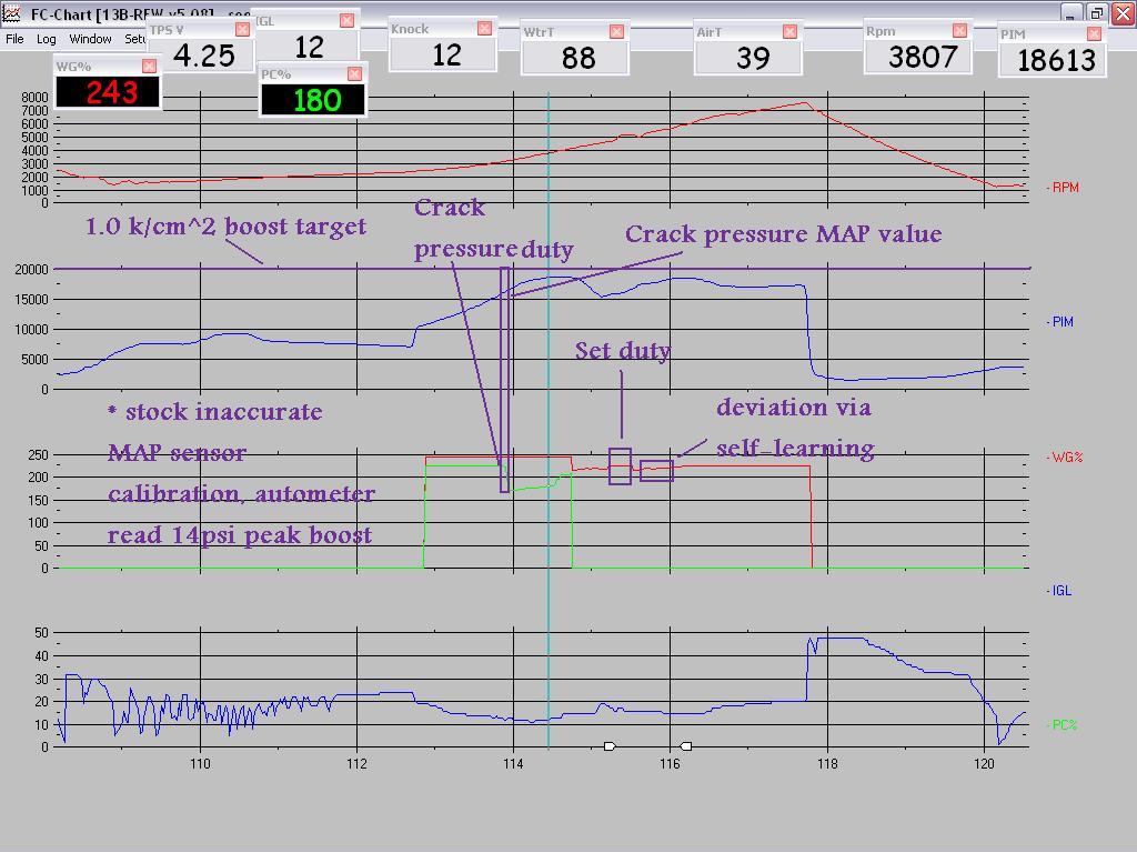
Consider this log from when I recently dyno tuned my friend's streeported FD with sequential turbos and supporting mods, max boost 14psi on the boost gauge. Factory [inaccurate] MAP sensor calibration retained.
Boost settings:
Pr 1.00 boost 70% duty
Sc .90 boost 86% duty
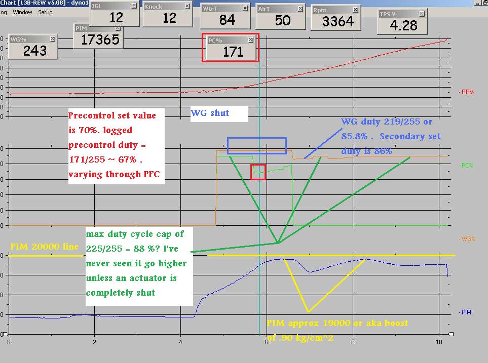
I have come to the conclusion that the primary duty value is in fact used (contrary to my last post) but the primary boost value is not. In that log ^ the PFC is controlling boost exactly as it has been configured, it's just that nobody really took the time to figure out how it works. You will see the boost dropping off up top. I suspect that is a mechanical issue unrelated to the PFC's control logic. These turbos may be tired out or they just may not be able to flow enough for a street ported car.
I'll speculate that one of the problems with transition is that the charge control valve snaps open essentially. With factory production tolerances this is not a big deal--it was compensated for in the design of the system. But when you start cranking the boost up you are asking an intricate system to do something it wasn't designed to do. I believe the mark IV Supra charge control equivalent is duty controlled so as to eliminate the need for a charge relief. It may be better during transition because it would open gradually.
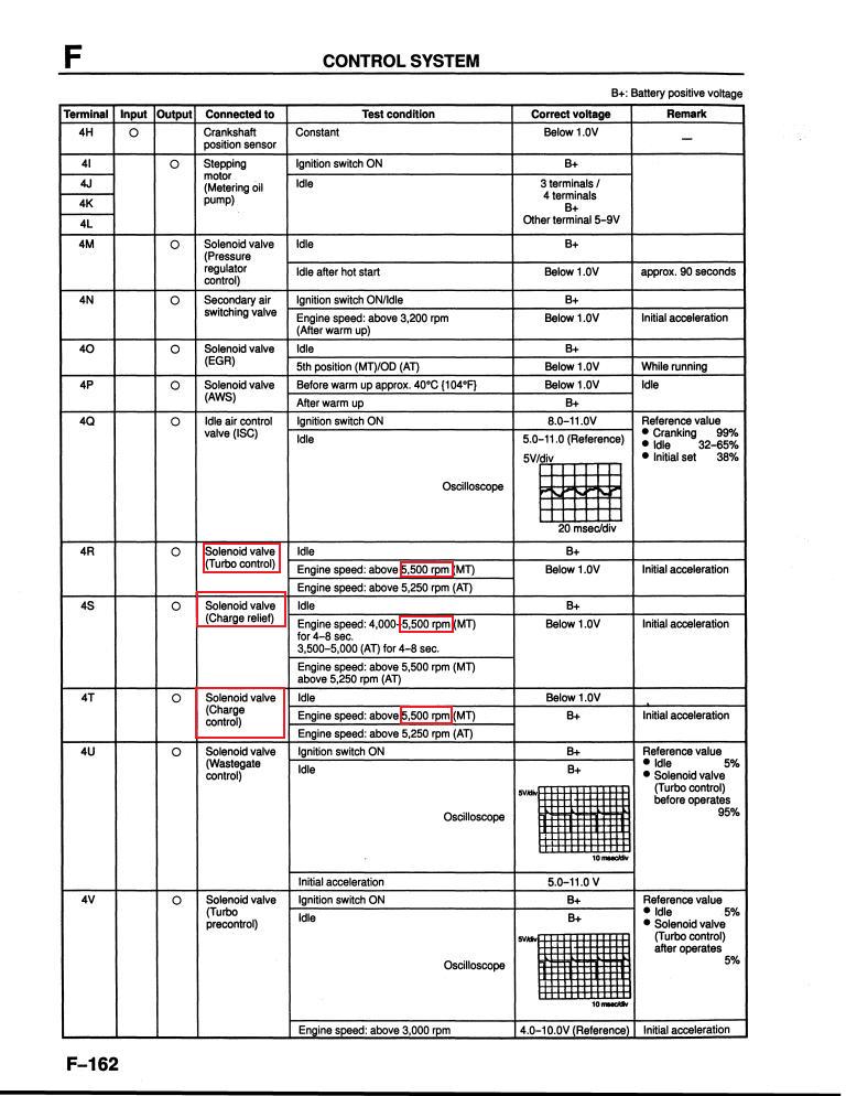
I forgot to log when the turbo control (not sure if it's the vacuum or the pressure one) ("TCN" sensor/output under etc screen) and charge control ("CCN") switched. Recall that when the turbo control actuator opens, both turbine wheels are fully fed exhaust in a non-sequential manner. When the charge control is switched, the butterfly valve in the Y pipe opens, the charge relief valve closes, and the secondary turbo's compressed air fully combines with that of the primary's.
If the FSM is to be trusted, we can reasonably assume that the charge control, charge relief, and turbo control all switch at about the same time. What combination of factors determines that exact point is not fully determined yet but the turbo transition settings have a lot to do with it.
what exactly do the low and high transition settings do on a PFC?
I don't have logs yet to see how closely the 'high' settings correlate with the switching of the actuators. The 'high' setting also has some bearing on when the precontrol goes fully open and the wastegate takes over, but my logs indicate that event does not directly correspond to the exact rpm value in the PFC.
The "low" transition setting determines the rpm when the PFC goes back into sequential mode on deceleration, after the secondary turbo has already come on line. Adjusting that rpm somewhat higher will eliminate some unpleasant driveability in some cases. With the default setting of 3000rpm, say you come off a light and give it half throttle, shifting at 5500. In this case your rpms drop to 3200 just as you shift into second. You are still non sequential though (the transition/hysteresis point is 3000 rpm), so while first gear felt really responsive second gear feels a bit sluggish. I have personally adjusted the 'low' transition point to 3500 rpm and eliminated this problem.
On the flipside, if you are autocrossing and don't like power drop during transition, you can set the "low" value low enough that you will stay non sequential the whole run, or so I have read (maybe 2000 rpm). Some have speculated that setting the "low" value to 0 or maybe 1000 rpm would result in the car running non sequential all the time. I have personally tested this theory and strangely enough, the car flips out and will not boost past 1 psi. I suspect that the charge control and charge relief open at the same time, essentially creating a massive boost leak. You can hear a ton of air escaping.
is the precontrol wastegate capable of controlling primary boost at higher than stock levels?
is it capable of diverting enough flow to the secondary turbo to secondary turbo to produce sufficient prespool for higher than stock boost levels?
what pattern of precontol and wastegate duty settings is needed to produce a smooth transition around a set transition point?
why does the PFC have a low and high setting for transition?
Once I get my Turbo II broken in I will be doing some testing on the single turbo boost control logic. I have gone so far as to retrofit a factory FD wastegate solenoid into my T2 to control pressure supplied to the top port of an external wastegate.
Joined: Jul 2003
Posts: 4,678
Likes: 97
From: Bay Area, CA
Thanks for the response.
I should have been clearer in some of my questions.
What I meant by 'is the precontrol wastegate capable of controlling primary boost at higher than stock levels?' is: does the increased flow on a modified FD (intake, ic downpipe, exhaust, etc.) overwhelm the precontrol channel at higher than stock boost levels? Clearly, removing the cat in association with these mods can overwhelm the wastegate. Does the same happen to the precontrol channel?
My suspicion based on [many] tests that I have done with a pair of dual manual controllers is that the precontrol channel is up to the task here - at least up to 14 psi. However, some BNR stage III owners, for example, have reported running 13-11-17 psi patterns or the like because they cannot convince the stock control system to give them higher primary boost.
The question 'is it capable of diverting enough flow to the secondary turbo to secondary turbo to produce sufficient prespool for higher than stock boost levels?' is pretty crucial. My [unconfirmed] suspicion is that the amount of flow through the precontrol channel is not enough to sufficiently prespool the secondary turbo at higher than stock boost levels, resulting in a huge dip in transition.
I've done extensive debugging on my stock sequential control system and as far as I can tell everything is working properly. However, at, say, 14 psi my transition dip is to 10 psi. No amount of tweaking can give me a better transition.
Since my goal is to run M2 twins sequentially at ~17psi, I am concerned that I may never get a decent transition.

Thread
Thread Starter
Forum
Replies
Last Post
avcr, control, crack, fd3s, higher, pfc, pfcdatalog, pre, precontrol, pressure, rx7, sequential, solenoid, transition, turbo, wastegate