
Power FC PFC to control REW in 85 GSL-SE

PFC to control REW in 85 GSL-SE
I've been doing countless hours of research in order to try to figure out what I'll need in order to install an REW into my 85 GSL-SE using PFC. unfortunately, Banzai does not make a patch cable so I need help on the wiring aspect. If you are familiar or good at wiring and know what I'll need, please chime in.
info:
-REW with stock twins, will be removing all unnecessary accessories and only keeping waterpump (S4 waterpump so impeller spins opposite of REW waterpump - belt routing purposes) and alternator. also doing simplified seq.
-FD engine harness
-12a front cover
-Blocking off OMP
-FC CAS (is there a difference between S4 or S5?) I have a CAS but not sure from which one, the following numbers are on it but google was no help: NF01 78 230A, 029400 0191 on second line, 13b on third line.
questions:
-can I simply cut the 4 wire plug from the CAS and wire it to the 2 plugs on the FD harness
-read that FC requires MAP sensor because FD MAP plugs into chassis harness, assuming the same with this swap
-wiring to work w/ gauge cluster?
i'm a wiring newb so any help is greatly appreciated.
-can I simply cut the 4 wire plug from the CAS and wire it to the 2 plugs on the FD harness
Yes, use this to make a connector for it instead of a direct splice...
RX-7 86-92 CAS Connector
-read that FC requires MAP sensor because FD MAP plugs into chassis harness, assuming the same with this swap
Yes, plug in a stock FD map sensor or buy a new GM 3 bar map sensor which will need to be wired in correctly and then the settings changed on the PowerFC via datalogit.
-wiring to work w/ gauge cluster?
This may help you...
thewird


A CAS is a CAS. No difference in any of them.
As thewird said, yes you can cut the REW loom back to the CAS location and attach the CAS connector.
Do you have the REW loom? If so, this is a pretty straight forward swap.
As thewird said, yes you can cut the REW loom back to the CAS location and attach the CAS connector.
Do you have the REW loom? If so, this is a pretty straight forward swap.

The FD emissions harness will only have plugs 3 & 4, you will still need to find plugs 1 & 2. Plug 1 being very important since it has the 12V + to power up the ECU and all the ignition control wires along with the MAP sensor signal.
You will need to be very capable at wiring and reading wiring diagrams to make this work.
You will need to be very capable at wiring and reading wiring diagrams to make this work.
^ You can probably buy Banzai's patch harness to aid you in this job as it will come with the connectors so you can just splice the wires you need.
I'm probably gonna sell mine though (as I'm going 20b). I don't remember what I spliced into it, probably only the injectors signals for the Aquamist water injection system. If your interested shoot me a PM.
thewird
I'm probably gonna sell mine though (as I'm going 20b). I don't remember what I spliced into it, probably only the injectors signals for the Aquamist water injection system. If your interested shoot me a PM.
thewird
first, thanks to thewird for the banzai patch harness.
hi guys,
after almost a year, i have yet to start the swap due to a busy schedule. prior to starting the swap, i wanted to make sure i have an understanding of the wiring involved so i just started to look at the diagrams. again, total newb in terms of wiring so am learning but here's my understanding...
i've taken my REW harness and have labeled most connectors and have a slight better understanding than i did a few days ago. so the Emission harness (EM in the FSM, some call it the engine harness) contains only connectors 3 and 4 to the ECU as mentioned by banzai. i would not have to modify anything on these 2 connectors (for now) but one would need to find connectors 1 and 2 since those connect mainly to the Front harness (F).
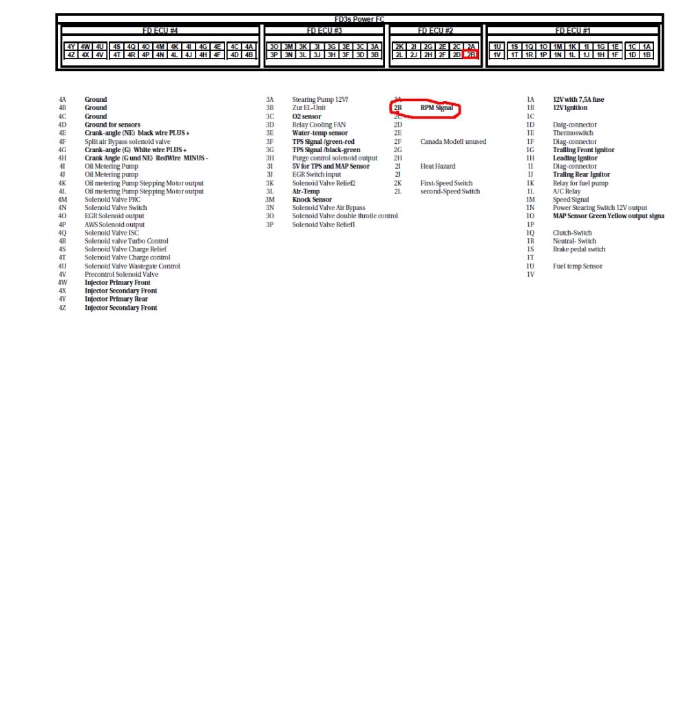
please help me make sure I'm understanding this correctly. connector 1 on the REW contains some vital items such as power to the ECU, ignitor, fuelpump relay, etc. looking at the wiring diagrams for both the REW and GSL-SE, is this how i would patch them together?
REW to GSL-SE
1A - not sure where to pull this from yet
1B - get from X-07 connector on GSL-SE F harness, wire BR
1K - wire fuel pump directly to battery with relay using this as its switch
1Q - get from B-02 connector on GSL-SE F harness, wire RY
1R - get from B-05 connector on GSL-SE F harness, wire LB
since the stock MAP sensor is on the REW F harness, then i would need to create my own. MAP has 3 wires G/Y goes to 1O, BR/W can be pulled from BR/W on the X-05 connector, and B/LG can be pulled from BR/B on the X-05 connector also. B/LG also goes to the diagnosis connector which i don't believe i'll need.
i'm not sure how the ignitor/coils will work yet (that's why i don't have anything for the Tach - 2B) as i haven't looked into it but if you are familiar, please provide any insight.
also trying to figure out the use of the FC CAS. here's an except from a PFC install guide for the FC:
"CAS:
Make sure you use shielded wires from the ECU to the CAS. This wires are very important for
ignition control of the ECU. Electrical devices like igniter, plug- wires and ignition coils may
influence the CAS signal which may lead to improper timing control and engine damage. For this
reason, please do not use regular wires for CAS use shielded wires instead. You can solder the
green and the red wire together, them are connected to 4H pin on Apexi PowerFC. Make sure, the
black and the white wire for NE+ and G+ are connected properly. Please pay special attention to the connectors which will join the CAS and the wiring. On the CAS side of connector the wires red and green are used for NE+ and GE+ on the wiring side to the ECU the colour will change to black (NE+) and white (G+)."
please let me know if i'm reading the above correctly...
W from B1-48 connector from REW EM harness goes to G from E-08 on the CAS
B from B1-49 connector from REW EM harness goes to R from E-08 on the CAS
this was never mentioned but...
R and G from B1-48/49 connectors from REW EM harness go to L and W from E-08 on the CAS? both are (-).
am i reading the wiring diagrams remotely correct???
hi guys,
after almost a year, i have yet to start the swap due to a busy schedule. prior to starting the swap, i wanted to make sure i have an understanding of the wiring involved so i just started to look at the diagrams. again, total newb in terms of wiring so am learning but here's my understanding...
i've taken my REW harness and have labeled most connectors and have a slight better understanding than i did a few days ago. so the Emission harness (EM in the FSM, some call it the engine harness) contains only connectors 3 and 4 to the ECU as mentioned by banzai. i would not have to modify anything on these 2 connectors (for now) but one would need to find connectors 1 and 2 since those connect mainly to the Front harness (F).
please help me make sure I'm understanding this correctly. connector 1 on the REW contains some vital items such as power to the ECU, ignitor, fuelpump relay, etc. looking at the wiring diagrams for both the REW and GSL-SE, is this how i would patch them together?
REW to GSL-SE
1A - not sure where to pull this from yet
1B - get from X-07 connector on GSL-SE F harness, wire BR
1K - wire fuel pump directly to battery with relay using this as its switch
1Q - get from B-02 connector on GSL-SE F harness, wire RY
1R - get from B-05 connector on GSL-SE F harness, wire LB
since the stock MAP sensor is on the REW F harness, then i would need to create my own. MAP has 3 wires G/Y goes to 1O, BR/W can be pulled from BR/W on the X-05 connector, and B/LG can be pulled from BR/B on the X-05 connector also. B/LG also goes to the diagnosis connector which i don't believe i'll need.
i'm not sure how the ignitor/coils will work yet (that's why i don't have anything for the Tach - 2B) as i haven't looked into it but if you are familiar, please provide any insight.
also trying to figure out the use of the FC CAS. here's an except from a PFC install guide for the FC:
"CAS:
Make sure you use shielded wires from the ECU to the CAS. This wires are very important for
ignition control of the ECU. Electrical devices like igniter, plug- wires and ignition coils may
influence the CAS signal which may lead to improper timing control and engine damage. For this
reason, please do not use regular wires for CAS use shielded wires instead. You can solder the
green and the red wire together, them are connected to 4H pin on Apexi PowerFC. Make sure, the
black and the white wire for NE+ and G+ are connected properly. Please pay special attention to the connectors which will join the CAS and the wiring. On the CAS side of connector the wires red and green are used for NE+ and GE+ on the wiring side to the ECU the colour will change to black (NE+) and white (G+)."
please let me know if i'm reading the above correctly...
W from B1-48 connector from REW EM harness goes to G from E-08 on the CAS
B from B1-49 connector from REW EM harness goes to R from E-08 on the CAS
this was never mentioned but...
R and G from B1-48/49 connectors from REW EM harness go to L and W from E-08 on the CAS? both are (-).
am i reading the wiring diagrams remotely correct???
Please post exact screenshots, with arrows and other markings made in MS paint of the relevant wiring diagrams and pinouts you are looking at. As I'm sure you know, it's a lot of work to go through all this stuff and you will get the most help if you make it easier on the people you are asking for assistance.
Trending Topics
of course, anything to make this easier for everyone...
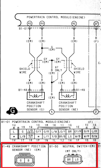
so here's the GSL-SE EM. the items highlighter are where i would pull the wires for the 12v Ignition, Clutch Switch (although it's been told to me i could just ground this and not have to use the clutch to start the car), and Neutral Switch:
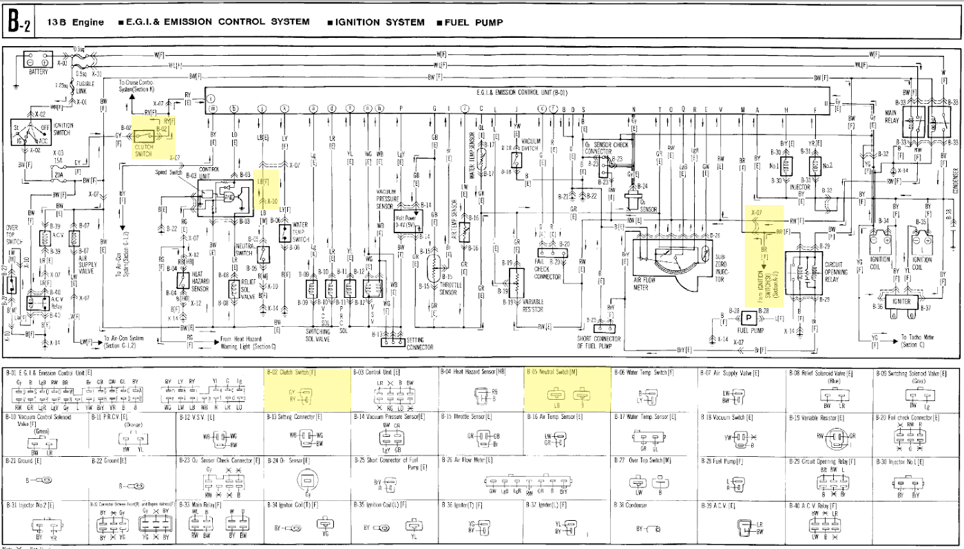
here's the wiring for the MAP, since i do not have the F harness of the REW, I could simply get the 2 wires from the EM harness and G/Y would go to pin 1O on the PowerFC:

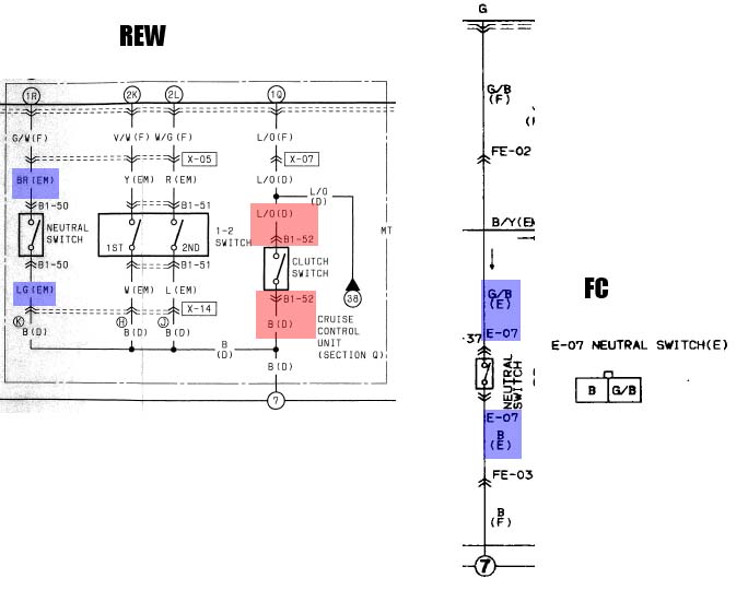
the one that's confusing to me at the moment is the CAS. reading the instructions on installing a PowerFC into an FC, the FC CAS "G" wire is the G+ signal while "R" is the NE+ signal. but looking at the pinout for the FC ECU, it looks like it should be the "L" and "W" wires. here's the pic (background is the REW CAS wiring, middle is the FC CAS wiring, and foreground is the FC CAS pinout on the ECU:

and here's another section from the PowerFC into an FC guide that also adds to my confusion:
"Remember, on the CAS side, the red and the green wires are signal wires, where as the two
black wires are ground. On the harness side, the colour will change! Now we need to look at the
black white wire (the should join the red, green on the CAS wiring) and not for the red green, at the
red green on the loom side is connected to the ground (the two black wires on the CAS)."
so here's the GSL-SE EM. the items highlighter are where i would pull the wires for the 12v Ignition, Clutch Switch (although it's been told to me i could just ground this and not have to use the clutch to start the car), and Neutral Switch:
here's the wiring for the MAP, since i do not have the F harness of the REW, I could simply get the 2 wires from the EM harness and G/Y would go to pin 1O on the PowerFC:
the one that's confusing to me at the moment is the CAS. reading the instructions on installing a PowerFC into an FC, the FC CAS "G" wire is the G+ signal while "R" is the NE+ signal. but looking at the pinout for the FC ECU, it looks like it should be the "L" and "W" wires. here's the pic (background is the REW CAS wiring, middle is the FC CAS wiring, and foreground is the FC CAS pinout on the ECU:
and here's another section from the PowerFC into an FC guide that also adds to my confusion:
"Remember, on the CAS side, the red and the green wires are signal wires, where as the two
black wires are ground. On the harness side, the colour will change! Now we need to look at the
black white wire (the should join the red, green on the CAS wiring) and not for the red green, at the
red green on the loom side is connected to the ground (the two black wires on the CAS)."
Last edited by craaaazzy; Aug 26, 2013 at 10:15 AM.
right, there are 4 wires from the FC CAS, green, red, and 2 white/black.
and here's a link to the PFC to FC3S: http://www.google.com/url?q=http://w...VVMFIouA54DLOA
and here's a link to the PFC to FC3S: http://www.google.com/url?q=http://w...VVMFIouA54DLOA
1A to the PowerFC, i will simply use a new wire with the appropriate inline fuse
1K i don't believe is an actual fuel pump signal so the best way would be to run a new wire to the fuel pump with 12v ignition as the switch, right?
1K i don't believe is an actual fuel pump signal so the best way would be to run a new wire to the fuel pump with 12v ignition as the switch, right?
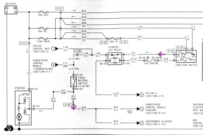
i believe i have 1B incorrect (what i stated before is just the ignition switch, not actual 12v power).
so now 1B would get power from RW from the front harness on connector X-07 which is power from one of the main relays. [it's to the right of the right most yellow box in the first picture of post #8].
so now 1B would get power from RW from the front harness on connector X-07 which is power from one of the main relays. [it's to the right of the right most yellow box in the first picture of post #8].
You have to be careful with that writeup. I've seen it before, and there are a few improvements that could be made. First thing you need to do is look at the FD factory service manual pinouts, because the PFC pinout is basically the same (except for a few unimportant wires that are for JDM cars).
One thing I think you're forgetting about is the connector pinouts. You need the ECU pinout, the connector pinout, AND the wiring diagrams to make sense of this. Furthermore, you should be reading the FD service highlights document, fuel and emission control section, to understand how the various systems on the FD work (2 speed fuel pump for example, and crank angle sensor waveform).
1A is constant. 1B comes from the main relay. 1C comes from the starter switch circuit (key in start position). 1T switches the fuel pump on--don't wire it to a switch, use it to control your main fuel pump relay. On series 3 and series 4, the fuel pump/circuit opening relay was controlled by the airflow meter circuit, just like an old Bosch L Jetronic system. Pin 1K is for the two-speed fuel pump resistor relay, which you don't need.


Put the Green wire (FC ECU pin 1N) to the White FD (pin 4G) G signal wire, the Red wire (FC ECU pin 1T) to the FD Black Ne (FD pin 4E) signal wire. Then put the adjacent wire to the associated connector on the FD harness.
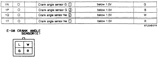
Look at the FC crank angle sensor connector diagram. Think of the left side as going to the FD G sensor, and the right side as going to the FD Ne sensor. The diagrams could be wrong due for whatever reason, like they just may not reflect the production date of your harness. I've noticed a couple wire color changes in FC's that have a pre 87 1/2 build date.
ehh I highlighted the neutral switch there, but you get what I mean about looking at the connector diagrams.
If anyone sees a mistake in anything I said, please let me know. This is exactly why we have the Banzai Racing jumper harness for normal applications of the PFC.
One thing I think you're forgetting about is the connector pinouts. You need the ECU pinout, the connector pinout, AND the wiring diagrams to make sense of this. Furthermore, you should be reading the FD service highlights document, fuel and emission control section, to understand how the various systems on the FD work (2 speed fuel pump for example, and crank angle sensor waveform).
Put the Green wire (FC ECU pin 1N) to the White FD (pin 4G) G signal wire, the Red wire (FC ECU pin 1T) to the FD Black Ne (FD pin 4E) signal wire. Then put the adjacent wire to the associated connector on the FD harness.
Look at the FC crank angle sensor connector diagram. Think of the left side as going to the FD G sensor, and the right side as going to the FD Ne sensor. The diagrams could be wrong due for whatever reason, like they just may not reflect the production date of your harness. I've noticed a couple wire color changes in FC's that have a pre 87 1/2 build date.
ehh I highlighted the neutral switch there, but you get what I mean about looking at the connector diagrams.
If anyone sees a mistake in anything I said, please let me know. This is exactly why we have the Banzai Racing jumper harness for normal applications of the PFC.
thanks arghx. i'll need to look at your post more closely within the next few days and make sense and digest it (just busy with work at the moment). much appreciated.
alright, i had some time to take a look at this and concentrate on Plug #1.
here's what i BELIEVE needs to be wired (i do have questions on a few wires, especially the ignition/coil wires, stoplight switch, and thermoswitch, and also need confirmation on the wires i've got labeled as "Not needed"). please let me know if you see anything that needs to be corrected:
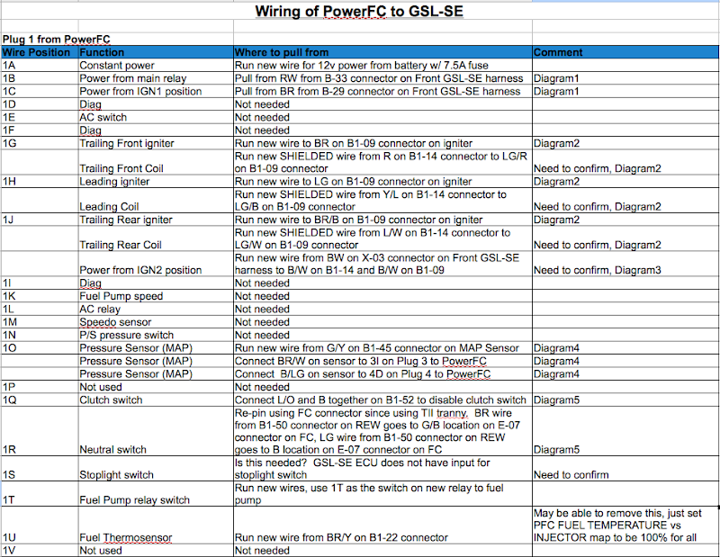
Diagram1:

Diagram2:
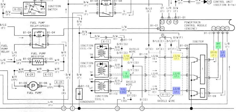
Diagram3:
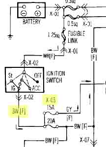
Diagram4:

Diagram5:
here's what i BELIEVE needs to be wired (i do have questions on a few wires, especially the ignition/coil wires, stoplight switch, and thermoswitch, and also need confirmation on the wires i've got labeled as "Not needed"). please let me know if you see anything that needs to be corrected:
Diagram1:
Diagram2:
Diagram3:
Diagram4:
Diagram5:
The one you have labeled red in diagram4 (for pin 1O): source you have labeled is 3I. Keep in mind that constant 5V wire is also used with the TPS. The TPS connector and wires is going to be on the other harness. It's up to you how you want to run them. I've never wired up an FD Trailing coil. Banzai Racing might answer that for you: Chris devised a clever solution of putting together two FC coils for trailing and one FC coil for leading. There's a writeup on the Banzai website, the part about installing a PFC in a series 4 Rx-7. In fact, the FC ignition system is considered stronger than the FD system. You might want to ditch FD ignition altogether if you can figure out how to mount everything. The FC has fender-mounted coils with long plug wires.
Pin 1Q (clutch switch) seems to have an effect on the idle control, especially on the stock FD ECU. I'm not saying it's impossible to make the car idle stably on deceleration without it, but you'd be better off if you had it working. Doesn't your GSL-SE have one for cruise control? That's the one it connects to on an FD, not the one for the starting safety switch. Neutral switch might have an effect, but I would be most comfortable deleting that. Vehicle speed sensor can have an effect on deceleration idle behavior, but you can get rid of that.
Let me put it to you this way: if you use "manual" open loop idle (idle speed targets set to 0), you can delete the clutch switch, neutral switch, vehicle speed sensor, and idle speed control valve (which is not on connector 1). However it will have all the normal issues associate with that, like more difficult cold starts. Plenty of people do it but it requires careful tuning of the throttlebody and fuel/timing maps plus a higher base idle. Then again, even with "regular" idle mode it requires some tuning and patience.
Stoplight switch, and fuel thermosensor are not needed. Simplest solution with manual idle is, don't even hook up wires for stoplight, fuel sensor, neutral switch, vehicle speed, clutch switch. You won't even need to close the circuits like you're proposing, because all those will not be inputs for the ECU's calculations.
What shielded wire do you plan on running?
the reason i have the MAP wired to 1O, 3I, and 4D is so i can install it inside the car close to the PFC.
I will take a look at Banzai's instructions (I have glanced at it before though). I did not know the FC ignition was better than the FD's so will definitely look into it.
that's good to know that i can leave all those switches/sensors out. that'll make wiring that much easier.
as for shielded wire, not sure but if u have recommendation, that would be good. this may be mute if i can figure out the FC igniter/coil set up though.
alright, may have to rethink about putting the MAP sensor inside the car. forgot that a vacuum line is needed. but as long as i'm understanding the wiring, then i can splice it at another location.
looking at the CAS wiring again, this should be the right way now:

now looking at the ignition system and following banzai's instructions on the dual FC trailing igniters for PFC, here's a graphical representation of the work required (let me know if this is incorrect though):

power goes to the leading coil/ign 2-pin connector wire B/Y as well as to the trailing coil/ign 2-pin connector with the 2 B/Y wires. seems like the best way to do this is to run a new power wire from the battery with a 40A fuse triggered by ignition.
now here's what's confusing for me. G/Y on the leading coil/ign 2-pin connector, do i connect it to 1H on the PFC? As for the training coil/ign 4-pin connector, does L/Y get connected to both 1G and 1J from the PFC?
And finally, how is RPM retrieved since Y/L and L/R are spliced together and not attached to the igniters any more?
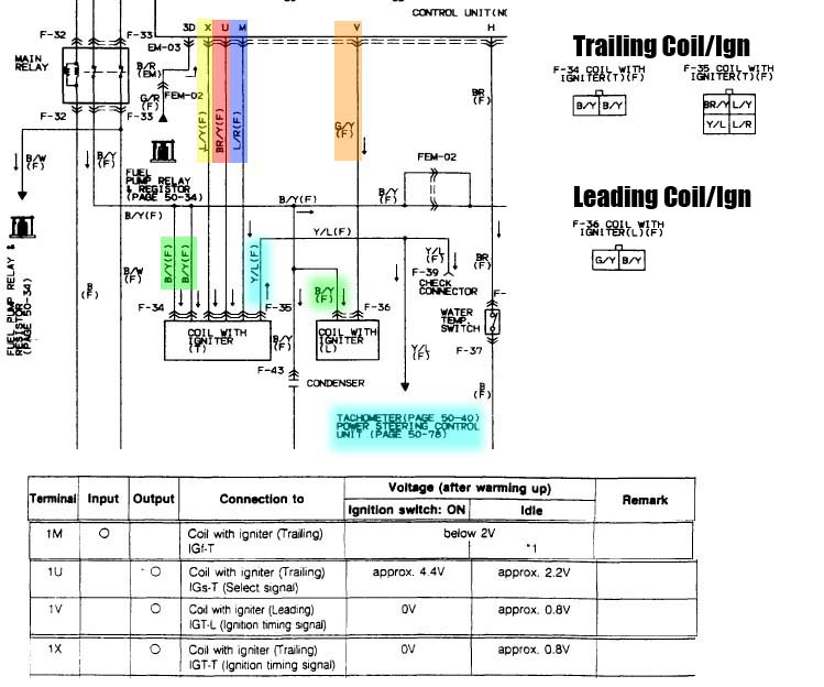
here are the pics on the ignition systems.
FC Ignition system:
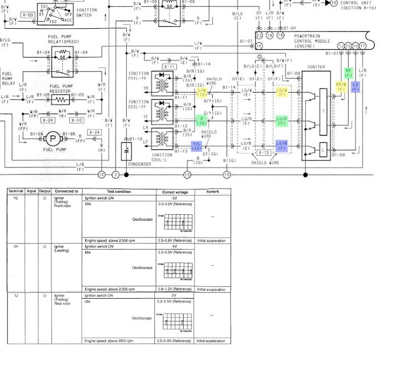
FD Ignition system:
looking at the CAS wiring again, this should be the right way now:
now looking at the ignition system and following banzai's instructions on the dual FC trailing igniters for PFC, here's a graphical representation of the work required (let me know if this is incorrect though):
power goes to the leading coil/ign 2-pin connector wire B/Y as well as to the trailing coil/ign 2-pin connector with the 2 B/Y wires. seems like the best way to do this is to run a new power wire from the battery with a 40A fuse triggered by ignition.
now here's what's confusing for me. G/Y on the leading coil/ign 2-pin connector, do i connect it to 1H on the PFC? As for the training coil/ign 4-pin connector, does L/Y get connected to both 1G and 1J from the PFC?
And finally, how is RPM retrieved since Y/L and L/R are spliced together and not attached to the igniters any more?
here are the pics on the ignition systems.
FC Ignition system:
FD Ignition system:

Joined: Mar 2001
Posts: 31,857
Likes: 3,243
From: https://www2.mazda.com/en/100th/
the FC is a bit weird. the leading is the same as the FD, output of ecu goes right to ignitor, which goes to coil (although they are physically in the same box).
the trailing on the FC is where it gets odd. there is a IGt-T signal (timing), pin 1G on an S5, which triggers every time the trailing ignition fires. then there is an IGs-T signal, pin1J on an S5, which selects which coil is fired. so the IGt-T triggers every time the trailing needs to fire, but the IGs-T will alternate as it switches between the T1 and T2 coils.
when the coil fires, it sends a signal back to the ecu pin 1V, the IGf-T
so when you use the FC ignition in an FD/PFC, the leading is ok, but the trailing ignitor needs to be changed, for two separate ignitors.
And finally, how is RPM retrieved since Y/L and L/R are spliced together and not attached to the igniters any more?
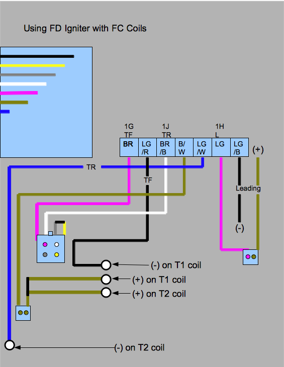
We have a write up for installing an FD igniter with FC coils that you may find helpful, just reference the bottom half if you are planning on using the FD coils:
FD Igniter Installation How To
RPM signal to the tach comes from the PFC pin 2B
FD Igniter Installation How To
RPM signal to the tach comes from the PFC pin 2B
Last edited by Banzai-Racing; Sep 7, 2013 at 10:59 AM.
thanks arghx.
thanks for the info on the RPMs coming from the CAS j9fd3s. so that means i just need to connect my RPM wire to 2B as Banzai mentioned. also, thanks for explaining how the FC ignition system works...quite different than the FD system with its switching.
Banzai, i did glance at your instructions for using the FD igniter before but didn't pay too much attention since i did not want to do that but i have studied it a bit, i believe i get how your dual igniter system works now and understand which wires to use, using reverse engineering. here's the graphical representation of the modification required to use the FD igniter (definitely helped me since i'm more of a visual person):
so...
-1H (from PFC) is the output for the leading coil, connect to Pink wire on leading coil/ign 2-pin connector
-1G is the output for the Trailing Front which uses the first igniter, connect to Pink wire on trailing coil/ign on 4-pin connector
-1J is the output for the Trailing Rear which uses the second igniter, connect to White wire on trailing coil/ign on 4-pin connector
-Run new wire for power (with 40A fuse) using relay with ignition as switch, connect to both tan wires on trailing coil/ign 2-pin connector as well as to the tan wire on the leading coil/ign 2-pin connector
can someone confirm this? if good, i think the last thing i need to figure out in terms of wiring are the stock electric FD fans with all their relays. thanks.
ok, haven't gotten any responses but i hope the above is correct for installing the FC igniters/coils.
looking at Dale Clark's information about the REW fans, seems like I can do this via 2 new relays. one relay will be triggered by the PFC using 3D on the harness (which uses the coolant temp sensor on the back of the waterpump, 2 wire sensor and set temp to 85 degrees) and the second relay will be triggered by the thermoswitch (single wire sensor on back of the waterpump, could upgrade this to the FC one which is a cooler temp sensor, 97 versus 107 degrees). the power from these relays will then go to the Blue and Green wires respectively, on the fan motors and the Black and Yellow wires on the fan motors go to ground. If only Blue sees power, then low speed. if only Green sees power (although I don't see this happening), medium speed. if both Blue and Green see power, then high speed. sound about right?
looking at Dale Clark's information about the REW fans, seems like I can do this via 2 new relays. one relay will be triggered by the PFC using 3D on the harness (which uses the coolant temp sensor on the back of the waterpump, 2 wire sensor and set temp to 85 degrees) and the second relay will be triggered by the thermoswitch (single wire sensor on back of the waterpump, could upgrade this to the FC one which is a cooler temp sensor, 97 versus 107 degrees). the power from these relays will then go to the Blue and Green wires respectively, on the fan motors and the Black and Yellow wires on the fan motors go to ground. If only Blue sees power, then low speed. if only Green sees power (although I don't see this happening), medium speed. if both Blue and Green see power, then high speed. sound about right?
wow, 3 year old bump! wasn't sure if i should bump this or create a new one so I'll try this first...
I believe I'm only a few weeks away from getting the car ready for its first start up so I wanted to go ahead and see if I could find a base map for the following:
-RX7Store stage 3 ported engine w/ 12a front cover
-stock primary injectors, FFE Step up kit w/ Bosch 1650cc secondary injectors (includes Fuelab fpr)
-Bosch 044 fuel pump
-Pettit intake
-Downpipe to custom 3" exhaust, no cat, only muffler
-no OMP
-custom vmounted intercooler
-Greddy elbow
-no emissions (most everything that could be blocked off is)
-no airpump (only alternator and waterpump)
please let me know if there is any other information that's needed.
thanks!