
Power FC Exhaust Oxygen Offset with Secondary Air runniing


Thread Starter
Joined: Aug 2006
Posts: 398
Likes: 8
From: Space Coast Florida
Exhaust Oxygen Offset with Secondary Air runniing
Does anyone know what the Oxygen offset is with the Secondary air pump running as measured in the exhaust gas? Or is there a map of the offset available relative to the engine operating parameters?
I suppose there would be a difference between the mode (Port air and Port air Bypass) and engine load, rpm conditions. Acknowledge that Split Air would not matter and mine is disabled anyway.
The reason I ask is I would like to continue to use the secondary air system but also obtain accurage WBO2 measurements for tuning and monitor. This may be in the "too hard bag" but would like to try.


Joined: Mar 2001
Posts: 31,849
Likes: 3,238
From: https://www2.mazda.com/en/100th/
if you have a look at the manuals, the air pump is off or venting to the air cleaner over about 2500rpms. its probably load dependent too (the 79-91 cars are)
i've never measured an fd with a wideband
idle will be full lean on a narrow band, an FC with a wideband will read 16-18:1
as i recall on an FD, the thing will be in closed loop (14.7+/-) from 1200?-3199rpm, as long as the boost stays under 1psi.
over 1psi or 3200 rpms its open loop, air pump off/vented
Thread Starter
Joined: Aug 2006
Posts: 398
Likes: 8
From: Space Coast Florida
Yea, it would appear that way but the Port Air Bypass is open (bleeding air into the port) on medium load both cold and warm and Switching is in the Port position at medium load cold (providing air to the port area). With that said, however, Relief 1 (which I think is the Secondary Air Baypass solenoid) is on medium load warm and off medium load cold venting the air only when warm. This would make me think that port air is being injected at medium load warm only other than, of course, the idle, and deceleration modes, .
Now with all that said I believe the pump clutch is disengaged over 3800 RPM overriding all of the load conditions.
It is very confusing.....
Regardless, I'm trying to get the engine mapped and wanted to understand the offset as the fuel mapping extends into all of the ranges. May have to do it with the clutch on the pump disconnected......
It's been a while, but from what I remember AFRs with the stock ECU were around 11-12 AFR at idle with the air pump disconnected and something like 16-17 with the air pump connected.
IMHO, it seems like it would be best to tune the engine with the air pump disconnected and then plug it back in later.
I doubt it will be a simple 'add X AFR points when the air pump is on' relationship because the volume of air being added by the air pump will only depend on engine speed, while the volume of air the engine is ingesting will vary depending on throttle and RPM and load (at the very least).
Last edited by scotty305; Jan 16, 2010 at 06:01 PM.
Thread Starter
Joined: Aug 2006
Posts: 398
Likes: 8
From: Space Coast Florida
It's been a while, but from what I remember AFRs with the stock ECU were around 11-12 AFR at idle with the air pump disconnected and something like 16-17 with the air pump connected.
IMHO, it seems like it would be best to tune the engine with the air pump disconnected and then plug it back in later.
I doubt it will be a simple 'add X AFR points when the air pump is on' relationship because the volume of air being added by the air pump will only depend on engine speed, while the volume of air the engine is ingesting will vary depending on throttle and RPM and load (at the very least).
IMHO, it seems like it would be best to tune the engine with the air pump disconnected and then plug it back in later.
I doubt it will be a simple 'add X AFR points when the air pump is on' relationship because the volume of air being added by the air pump will only depend on engine speed, while the volume of air the engine is ingesting will vary depending on throttle and RPM and load (at the very least).
Joined: Mar 2001
Posts: 31,849
Likes: 3,238
From: https://www2.mazda.com/en/100th/
I tend to believe you are right. I can tune with the pump disabled but after the tune and monitoring the WBO2 driving with the pump running will no doubt reveal something different. So, I'm trying to understand what offset to expect during normal driving as shown on the AFT gauge.
the only real tuning you might need to do, is at idle. since there is higher vacuum in the intake than the exhaust, it'll suck in a little fresh air from the air pump in the exhaust ports
Thread Starter
Joined: Aug 2006
Posts: 398
Likes: 8
From: Space Coast Florida
What I think happens is the PFC or stock ECM looks at the O2 sensor if in closed loop and makes necessary adjustments to try to achieve stoich. both idle and cruise loads.
When the air pump is running and air is being injected at the exhaust ports the O2 sensor will indicate a leaner condition.
Without an offset programmed into the PFC when the port air is flowing the engine management system will falsely interpret a lean condition and step up the injector duty cycle. and richen up the mixture. Which is not desired.
This appears to be the root of the problem when people remove the secondary air system and have a hard time getting a good idle (no extra air but ECM assumes there is).
What is not available in the Commander or Datalogit is visibility into the offset table.
So tuning needs to be executed with O2 FB turned off. But, I don't know if the offset is still being executed.
So the question is if tuning with the air pump running in the load ranges the air is being injected in the exhaust ports and the WBO2 is sensing the leaner condition is the PFC O2 voltage offset in play?
Or, the offset is disabled when the O2 is not in FB mode?
Regardless, if I knew what the offset is or if I even need to worry about it when setting the O2 out of FB mode. It really appears the clutch on the air pump needs to be disconnected when setting up the AFR using the O2 sensor.
Geez did I make any sense at all?
Trending Topics
Originally Posted by ttmott
Geez did I make any sense at all?
Here is my understanding of how the O2 feedback works in the PFC. I'll preface this by saying I have never messed with it before because I'm always working on cars without airpumps.
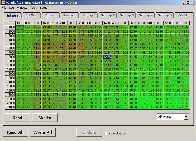
In settings 2 there is a setting to control the INJ map correction range (look at the INJ map in the normal "correction" view) where the closed loop will operate. These shots are from the regular basemap that comes in all but the earliest production PFC's.

See how that value is 1.047? That means that, any INJ map cell with a value of 1.047 or less will be under closed loop control.
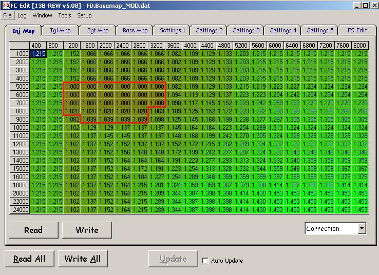
What that really works out to are these cells on the default map:
Now you need to understand how the PFC is supposed to work theoretically. It is actually a simplified version of Toyota OEM speed density--they use a lot of Toyota acronyms and such for the sensors. PIM (Pressure Intake Manifold), VTA (Voltage Throttle Angle), VS (voltage signal, used on MAF based PFC's) etc are all technical jargon that are utilized internally by Toyota engineers. I've got a bunch of internal Toyota documentation which discusses a lot of this.
Anyway, The Base map in the PFC is supposed to represent the pulsewidth needed to reach lambda=1 or 14.7:1 AFR. The INJ map is a correction map but it is really supposed to be a target AFR table or lambda table like you would find in OEM engine calibrations. Any INJ map correction value over 1.00 would correspond to an AFR richer than 14.7:1 or a lambda of less than 1.
So with an O2 feedback setting of 1.047 (the default), it is really saying that any cell in the INJ map with a target AFR of 14:1 or leaner will be under closed loop. If the target AFR is under closed loop, then the PFC will attempt to alter the mixture in order to get the factory narrowband sensor to oscillate around the switch point of about .5V .
So what does that mean from a practical perspective? There is no closed loop control at idle on a PFC with the default calibration.
The PFC was actually engineered to reach these target AFR's on a relatively stock car, just like a factory ECU is engineered to reach the values on their target AFR tables. But Chuck Westbrook was the first to point out that if you click "recalc" in the Datalogit, all your values will be set to 1.00 , and if all your values are 1.00 with in the 1.047 setting) then the PFC will be in O2 feedback when you don't want it to (like idle).
Now from the factory the basic airpump control logic is this:
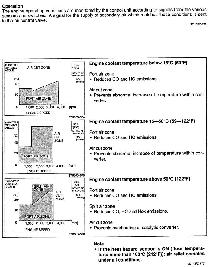
but apparently the PFC engages air relief above 2500rpm. We have no control over the PFC air pump logic directly, but you could wire in a toggle switch to turn on the switching and relief solenoids. That would dump the airpump air back into the aircleaner--that's exactly how the 2nd gens and earlier do it, because the airpump is not clutched. Look at the "air relief" section at the bottom:

Engaging the switching solenoid cuts vacuum to the switching valve in the ACV. That prevents air from going to the exhaust ports. Engaging the relief solenoid opens the relief valve inside the ACV, which vents secondary air to the air cleaner.
Thread Starter
Joined: Aug 2006
Posts: 398
Likes: 8
From: Space Coast Florida
Thanks and I appreciate the data; but didn't really get my question across so I'll try to break down:
When the air pump is injecting air into the exhaust ports the O2 sensor will indicate a leaner condition than the engine is actually putting out.
The engine control system needs to offset the "false lean" indication by some value when it commands the Secondary air system to inject air at the ports.
Without the offset the system would enrichen simply based upon what the O2 sensor is saying.
This is evident when the air pump is removed or disconnected and the idle significantly changes. (ECM thinks air is being injected but pump is removed. ECM reads O2 and offsets the actual engine exhaust to a leaner condition.)
This O2 voltage offset when port air is on is not a feature in the PFC Commander or Datalogit that I can find.
So I am trying to find what the offset is so I can get my instrumentation aligned.
Can we back up a little bit and try to determine exactly when the air pump is on? I presume you have a Datalogit. With O2 feedback on, can you take some logs to determine more precisely when the air pump and port air are engaged?
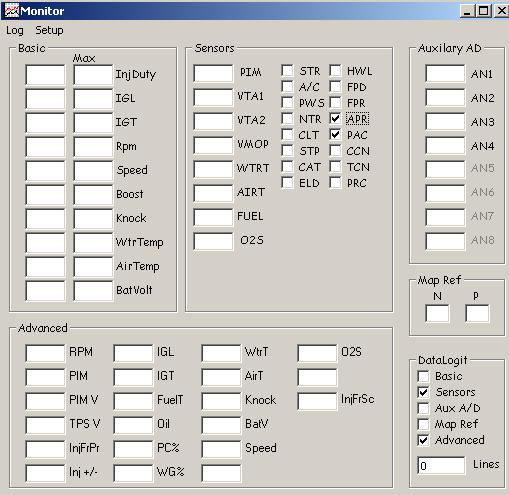
Do a drive cycle logging these parameters. By drive cycle I mean do a cold start, warm the engine up to operating temp in your driveway. Then just do some around-town driving. Logging sensors will let us see the factory O2 voltage. For the switches, the APR is listed as "airpump relay" and PAC is listed as "Port air control" in the PFC Commander manual.
I am unsure if the "port air control" they list is the actual port air bypass solenoid or the switching solenoid. According to the FSM and training manual the switching solenoid actually directs most of the air to the exhaust ports, while the port air bypass only bleeds a little bit of air into the exhaust ports. The port air bypass is listed as only running during "low speed, light load feedback" where split air is also utilized.
Post the log and post the map you used with it.
Thread Starter
Joined: Aug 2006
Posts: 398
Likes: 8
From: Space Coast Florida
I kinda knew this would come down to a science project. However, it looks as if the data may be valued on this site.
This is going to take some time to get together but I should also tie in to the aux ports of the Datalogit the switches for the bypass and switching so we know for sure.
Bear with me and I'll get this going.
This is going to take some time to get together but I should also tie in to the aux ports of the Datalogit the switches for the bypass and switching so we know for sure.
Bear with me and I'll get this going.
First of all, if you have it in the budget I recommend you acquire an engine patch harness which will go between your main engine harness and the Power FC. They are available from Banzai Racing and also from Boomslang. The wires will be 18 gauge and are much easier to work with than a lot of the tiny stuff on the FD harness. Plus you won't be hacking up the factory wires.
Second, what you really need to log is
pin 3N port air bypass -- used during cruising when air is directed to cat but a small amount of port air is required
pin 4N switching valve solenoid -- when ON (Grounded), directs air to split air pipe instead of exhaust ports. This is the most important valve on the ACV.
and the air pump relay (which is already loggable directly through the PFC as the APR switch). I guess if you really want some great logs you could basically log every emissions solenoid output on a separate channel. So that's
pin 3P relief 1 -- a sort of airpump "blowoff valve" used when the airpump is declutched
pin 3K relief 2 -- mostly used during cold start
pin 4F split air bypass -- used when all secondary air is directed to the cat
Thread Starter
Joined: Aug 2006
Posts: 398
Likes: 8
From: Space Coast Florida
Air pump running for sure but our objective is a little different. We are looking for how and how much the O2 voltage is offset when the air is being injected.
My Datalogit has 8 AN ports which are rated for 0-5 VDC. Obviously, if directly connecting to the FC pins the ports will see 12VDC when solenoids or clutch are off and close to zero when turned on. So we will use the analog ports as discrete on or off. Question is what is the current draw at the ports so I can size the voltage dropping resistors? My Datalogit user group authorization has not come through yet so can't get it answered there yet.
My Datalogit has 8 AN ports which are rated for 0-5 VDC. Obviously, if directly connecting to the FC pins the ports will see 12VDC when solenoids or clutch are off and close to zero when turned on. So we will use the analog ports as discrete on or off. Question is what is the current draw at the ports so I can size the voltage dropping resistors? My Datalogit user group authorization has not come through yet so can't get it answered there yet.
EDIT: I just checked the Datalogit manual, it does have to be between 0 and 5 volts. That complicates things. Maybe you should just log the APR and PAC switches.
Other option is to run some of these solenoids to other switch inputs you don't need, like exhaust overheat.
Thread Starter
Joined: Aug 2006
Posts: 398
Likes: 8
From: Space Coast Florida
0-5 VDC is the nominal value the Datalogit auxillary ports can tollerate. Don't want to smoke my brand new box. Relays referenced to +12VDC will probably be the best choice and triggered by the grounding from the PFC. Getting complicated but probably the best choice.
If I'm going to have to build a relay board I'll go ahead and pickup all of the secondary air components.
If I'm going to have to build a relay board I'll go ahead and pickup all of the secondary air components.

Thread
Thread Starter
Forum
Replies
Last Post
Skeese
Adaptronic Engine Mgmt - AUS
65
Mar 28, 2017 03:30 PM