
Power FC Chance to disable the OMP over PFC/Datalogit...?

Chance to disable the OMP over PFC/Datalogit...?
Hey Guys, i had removed my OMP and had also cut off the plug of the OMP from the engine harness, but as i have a jdm FD, my engine warning lamp tells me an error as my OMP isn't running...
...is there a chance to switch the OMP off with the datalogit...or change the VMOP relating features that the PFC won't tell the missing OMp as an error...?
...is there a chance to switch the OMP off with the datalogit...or change the VMOP relating features that the PFC won't tell the missing OMp as an error...?


strange, with the USDM units it doesn't have any ill effects removing the OMP completely that i recall. if you want to turn it off and leave the unit in place just set the figures all to 0.
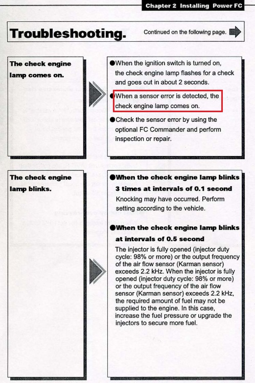
The check engine light is supposed to be illuminated if any sensors under etc --> sensor/sw check are highlighted. A PFC in a USDM car does not illuminate the check engine light due to wiring differences between USDM and JDM. On non Rx-7 Power FC's the check engine light will come on if a sensor is illuminated, and it can also flash if the MAF sensor is maxed out.
The whole check engine light thing should just be an annoyance. There won't be any actual problems from disconnecting the OMP. Now, all that being said... I've never worked on a PFC on an actual JDM car. I've just read the manuals for the Rx-7 and Evo Power FC's and I know the CEL comes on in Subaru PFC applications as well.
Not sure. This isn't a problem that arises too often. Most people posting about their Power FC don't have a JDM car. Maybe somebody else knows more about this from firsthand experience?

I think you're giving Apex'i too much credit. This is a Power FC. It's a pretty dumb ECU, even compared to the original series 6 factory computer. I'm pretty sure that as long as the VMOP isn't highlighted under sensor/sw check it won't illuminate the CEL.
Trending Topics
Originally Posted by arghx;
I think you're giving Apex'i too much credit. This is a Power FC. It's a pretty dumb ECU, even compared to the original series 6 factory computer. I'm pretty sure that as long as the VMOP isn't highlighted under sensor/sw check it won't illuminate the CEL.
...the sensor for the VMOP (or OMP...) reads 0.00V and so the PFC expects an error - thats why the engine check lamp comes on...
Curious situation, as european and us models doesn't have these problems...the european fd models don't have the engine check lamp at all...
Curious situation, as european and us models doesn't have these problems...the european fd models don't have the engine check lamp at all...
The PFC is a tuning platform where it doesn't make much sense to send messages to configurations that may or may not be there.
metalCORE, you are obviously getting a light; is it flashing a code? Are you looking at the CEL or Overtemp light? The light may be something else like knock, inj duty, or ELD failure. As a note the CEL is fed from the ELD.
The PFC only outputs warning for high knock count and high injector duty to the Exhaust Overtemperature Light; everything else is ignored, I believe, for the FD3S RX7. In fact a standard modification for the USDM cars is to move the knock and INJ Duty warning which is displayed on the Exhaust Overheat Light on the center console to the dash CEL which is unused with a PFC. For the JDM cars the Exhaust Overheat Light is in the dash so no mod is required. I have a coouple of things operating outside of the Mazda OEM specification (AWS disconnected, Mikuni OMP) and am not getting CEL lights
The PFC is a tuning platform where it doesn't make much sense to send messages to configurations that may or may not be there.
metalCORE, you are obviously getting a light; is it flashing a code? Are you looking at the CEL or Overtemp light? The light may be something else like knock, inj duty, or ELD failure. As a note the CEL is fed from the ELD.
Here is a test you can do to see if the light will go out. Basically you will be feeding 5VDC to to the PFC Pin 3A which would be expecting 4.1+/- VDC at maximum engine load. On the harness where you cut off the OMP connector locate the Green/Black wire and Brown/White wire and while the engine is running and someone watching the CEL short those two wires together (make darn sure you have the correct wires). This will simulate an OMP commanded full open flow signal to the ECM. Also check your commander and Datalogit; they should indicate the 5VDC. Now the wire colors I have given here are for the US car so make sure yours are the same before proceeding. Here are the resistance values for a Denso and Mikuni OMP at various positions:


And, here are the expected voltages for the OMP to pin 3A

Lastly, for the factory ECM there are expected voltages depending upon engine load. If the stock ecm does not see the expected value it will throw a code. There is a range of deviation and that is what I have been trying to determine for some time now. Regardless, in the below chart you can see how the oil injection and consequential VMOP is set. All of the curves are actual data from my engine; the Engine Load line is calculated by me to somewhat reverse engineer how the PFC establishes the OMP position. Obviously, the TPSV influences the curve but I have yet to determine the algorithym for it. So, if your PFC is throwing codes is it looking for anything above 0 volts or is it tracking a perceved curve like the stock ECM?

Lastly, for the factory ECM there are expected voltages depending upon engine load. If the stock ecm does not see the expected value it will throw a code. There is a range of deviation and that is what I have been trying to determine for some time now. Regardless, in the below chart you can see how the oil injection and consequential VMOP is set. All of the curves are actual data from my engine; the Engine Load line is calculated by me to somewhat reverse engineer how the PFC establishes the OMP position. Obviously, the TPSV influences the curve but I have yet to determine the algorithym for it. So, if your PFC is throwing codes is it looking for anything above 0 volts or is it tracking a perceved curve like the stock ECM?
The Power FC instructions specifically state that a warning light will come on if a sensor is out. It's really buried in the instructions though. FD Power FC:

and this is from the instructions for the Evo PFC:
5 bucks says anything above about 0 volts (just so the VMOP isn't highlighted on the Commander) but still below 5 volts will work. I was just dealing with a car having a GM MAP sensor problem the other day. It would either read 0 volts or exactly 5 volts (ref voltage) depending on how it was wired up. Both the 0 volt and the 5 volt readings would make the PFC highlight the MAP sensor in the Commander. Turns out it was a bad connector.
Also, think about how crude check engine codes are on 80s cars. All the error codes on a series 4 FC come up only if you have an open or short circuit on a sensor. It's the same way with a lot of OBD1 cars. The computer just isn't smart enough to compare the current values to some expected values. It's one of the reasons why you usually don't throw evaporative emissions diagnostic codes on OBD I cars.
and this is from the instructions for the Evo PFC:
Originally Posted by ttmott
So, if your PFC is throwing codes is it looking for anything above 0 volts or is it tracking a perceved curve like the stock ECM?
Also, think about how crude check engine codes are on 80s cars. All the error codes on a series 4 FC come up only if you have an open or short circuit on a sensor. It's the same way with a lot of OBD1 cars. The computer just isn't smart enough to compare the current values to some expected values. It's one of the reasons why you usually don't throw evaporative emissions diagnostic codes on OBD I cars.
The Power FC instructions specifically state that a warning light will come on if a sensor is out. It's really buried in the instructions though. FD Power FC:
and this is from the instructions for the Evo PFC:
5 bucks says anything above about 0 volts (just so the VMOP isn't highlighted on the Commander) but still below 5 volts will work. I was just dealing with a car having a GM MAP sensor problem the other day. It would either read 0 volts or exactly 5 volts (ref voltage) depending on how it was wired up. Both the 0 volt and the 5 volt readings would make the PFC highlight the MAP sensor in the Commander. Turns out it was a bad connector.
Also, think about how crude check engine codes are on 80s cars. All the error codes on a series 4 FC come up only if you have an open or short circuit on a sensor. It's the same way with a lot of OBD1 cars. The computer just isn't smart enough to compare the current values to some expected values. It's one of the reasons why you usually don't throw evaporative emissions diagnostic codes on OBD I cars.
and this is from the instructions for the Evo PFC:
5 bucks says anything above about 0 volts (just so the VMOP isn't highlighted on the Commander) but still below 5 volts will work. I was just dealing with a car having a GM MAP sensor problem the other day. It would either read 0 volts or exactly 5 volts (ref voltage) depending on how it was wired up. Both the 0 volt and the 5 volt readings would make the PFC highlight the MAP sensor in the Commander. Turns out it was a bad connector.
Also, think about how crude check engine codes are on 80s cars. All the error codes on a series 4 FC come up only if you have an open or short circuit on a sensor. It's the same way with a lot of OBD1 cars. The computer just isn't smart enough to compare the current values to some expected values. It's one of the reasons why you usually don't throw evaporative emissions diagnostic codes on OBD I cars.
...i will check that today, but as i said before and proven by the pics arghx posted, the exhaust temp goes on (no flashing), and as the the sensor table in the PFC also highlights the VMOP sensor and reads 0.00V, it is defintely that problem. Perhaps you never had that problem because it only occurs on jdm cars...?

Junior Member
Joined: May 2005
Posts: 27
Likes: 0
From: UK
following this thread with interest!!!
thanks for the expert suggestions, my JDM 94 FD does this too since the OMP removed - the PFC throws a sensor error and the engine check light comes on. I have a spare OMP/MOP and will borrow the loom and have a play. Definitely a JDM anomaly.
thanks for the expert suggestions, my JDM 94 FD does this too since the OMP removed - the PFC throws a sensor error and the engine check light comes on. I have a spare OMP/MOP and will borrow the loom and have a play. Definitely a JDM anomaly.
For a simple solution, what if you just spliced the OMP position sensor wire into say one of the TPS wires? then the voltage would never be out of range. So splice the wire on pin 3A (the OMP sensor input wire) to pin 3F (narrow range TPS signal) or pin 3G (full range TPS). Assuming the VOMP is highlighted for the same reason as every other sensor, using a good TPS signal for it should not cause a fault condition. Here's a crude MS paint diagram:
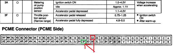
The VMOP and the VTA2 signals should be about the same now. All you're trying to do is make the CEL go off without a whole lot of hassle, and this should work if the PFC is as dumb as I think it is...
The same type of thing could be done if you remove your fuel temp sensor due to an aftermarket fuel rail. That would highlight the fuel temp sensor in the sensor screen of the commander, theoretically triggering a CEL on a JDM car. The fuel thermosensor wire is pin 1U. You could tap that into the water temperature sensor signal which is pin 3D. The two sensors are very similar anyway.
For a simple solution, what if you just spliced the OMP position sensor wire into say one of the TPS wires? then the voltage would never be out of range. So splice the wire on pin 3A (the OMP sensor input wire) to pin 3F (narrow range TPS signal) or pin 3G (full range TPS). Assuming the VOMP is highlighted for the same reason as every other sensor, using a good TPS signal for it should not cause a fault condition. Here's a crude MS paint diagram:
The VMOP and the VTA2 signals should be about the same now. All you're trying to do is make the CEL go off without a whole lot of hassle, and this should work if the PFC is as dumb as I think it is...
The same type of thing could be done if you remove your fuel temp sensor due to an aftermarket fuel rail. That would highlight the fuel temp sensor in the sensor screen of the commander, theoretically triggering a CEL on a JDM car. The fuel thermosensor wire is pin 1U. You could tap that into the water temperature sensor signal which is pin 3D. The two sensors are very similar anyway.

Thread
Thread Starter
Forum
Replies
Last Post