
No boost past 4,500 RPM - Are my hoses misrouted?


Thread Starter
Full Member
Joined: Oct 2013
Posts: 67
Likes: 0
From: Houston, Texas
No boost past 4,500 RPM - Are my hoses misrouted?
I'm having an issue where my boost is dropping to 0 past 4,500 RPM. I took a close look (or as close as I could get without removing the intake manifold) at all the vacuum lines, and it looks like the might be miss-routed. Wanted to get some conformation from you guys.
The lines I am referring to are circled in Red:
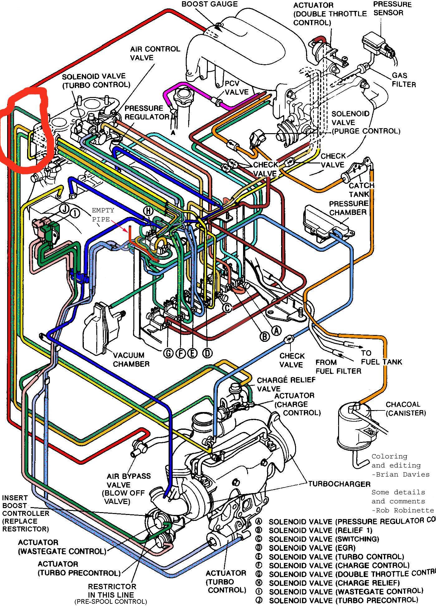
If you take a look at the Diagram, there are 3 hoses coming out of that area (Dark Green, Orange, Light Green). However, I have a 4 hoses coming from that area (Blue hose routed to the right, below that a blue hose routed to the left, below that a black hose, below that another blue hose)
Now, according to the diagram, here are where the vacuum lines are supposed to go:
1. Green (Top Hose): Charge pipe for secondary turbo
2. No Hose (looks like there's a little gap in the diagram)
3. Orange Hose: Attaches to the Charge Relief valve connected to the secondary turbo
4. Light Green (Bottom hose): Attaches to the Charge Control Actuator.
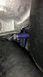
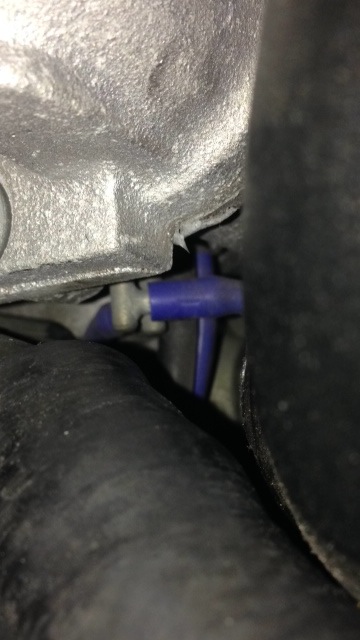
According to what I have, here is where my hoses are routed to:
1. Blue hose turning right (top hose): Connected to an actuator of some sort, cant figure out what it is. Its positioned directly in front of the Charge relieve valve actuator is you are looking at it from the passenger side fender.
2. Blow that, Blue hose turning left: Connected to an actuator that looks like controls the Charge Relief valve
3. Below that, black hose: This is not connected to anything. Also a key note, there is nothing connected to the Charge pipe on the secondary turbo, the nipple is left open.
4. Below that, blue hose: Going to charge relief valve.
I wanted to hear from you guys, am I reading the diagram completly wrong, or are the vacuum lines completely wonky?
The lines I am referring to are circled in Red:
If you take a look at the Diagram, there are 3 hoses coming out of that area (Dark Green, Orange, Light Green). However, I have a 4 hoses coming from that area (Blue hose routed to the right, below that a blue hose routed to the left, below that a black hose, below that another blue hose)
Now, according to the diagram, here are where the vacuum lines are supposed to go:
1. Green (Top Hose): Charge pipe for secondary turbo
2. No Hose (looks like there's a little gap in the diagram)
3. Orange Hose: Attaches to the Charge Relief valve connected to the secondary turbo
4. Light Green (Bottom hose): Attaches to the Charge Control Actuator.
According to what I have, here is where my hoses are routed to:
1. Blue hose turning right (top hose): Connected to an actuator of some sort, cant figure out what it is. Its positioned directly in front of the Charge relieve valve actuator is you are looking at it from the passenger side fender.
2. Blow that, Blue hose turning left: Connected to an actuator that looks like controls the Charge Relief valve
3. Below that, black hose: This is not connected to anything. Also a key note, there is nothing connected to the Charge pipe on the secondary turbo, the nipple is left open.
4. Below that, blue hose: Going to charge relief valve.
I wanted to hear from you guys, am I reading the diagram completly wrong, or are the vacuum lines completely wonky?


Thread
Thread Starter
Forum
Replies
Last Post